
J. Cent. South Univ. (2018) 25: 719-728
DOI: https://doi.org/10.1007/s11771-018-3776-x

Influence of CsNO3 as electrolyte additive on electrochemical property of lithium anode in rechargeable battery
LIN Hua(林华)1, CHEN Kang-hua(陈康华)1, 2, SHUAI Yi(帅毅)2, HE Xuan(何璇)1, GE Ke(葛科)2
1. State Key Laboratory of Powder Metallurgy, Central South University, Changsha 410083, China;
2. Light Alloy Research Institute, Central South University, Changsha 410083, China
 Central South University Press and Springer-Verlag GmbH Germany, part of Springer Nature 2018
Abstract: Lithium metal is one of the most promising anode materials for rechargeable battery with high energy density, but its practical use is still hindered by two main problems, namely, lithium dendrite growth and low Coulombic efficiency. To address the issues, cesium nitrate (CsNO3) is selected as the additive to modify the electrolyte for lithium secondary battery. Here we report electrochemical performance of lithium secondary battery with different concentration of CsNO3 as electrolyte additive. The study result demonstrates that Coulombic efficiency of Li–Cu cells and the lifetime of symmetric lithium cells contained CsNO3 additive are improved greatly. Li–Cu cell with 0.05 mol/L CsNO3 and 0.15 mol/L LiNO3 as electrolyte additive presents the best electrochemical performance, having the highest Coulombic efficiency of around 97% and the lowest interfacial resistance. With increasing the concentration of CsNO3 as electrolyte additive, the electrochemical performance of cells becomes poor. Meanwhile, the morphology of lithium deposited films with CsNO3-modified electrolyte become smoother and more uniform compared with the basic electrolyte.
Key words: cesium nitrate; lithium anode; electrolyte additive; Coulombic efficiency; electrochemical properties; morphology
Cite this article as: LIN Hua, CHEN Kang-hua, SHUAI Yi, HE Xuan, GE Ke. Influence of CsNO3 as electrolyte additive on electrochemical property of lithium anode in rechargeable battery [J]. Journal of Central South University, 2018, 25(4): 719–728. DOI: https://doi.org/10.1007/s11771-018-3776-x.
1 Introduction
Lithium metal has been considered one of the most promising anode materials for “next generation” rechargeable batteries for the sake that lithium has an extremely high theoretical specific capacity (3860 mA·h/g), low density (0.534 g/cm3), and the lowest negative electrochemical potential (-3.040 V vs. SHE) [1-4]. However, although great effort has been done to address the intrinsic problems of lithium metal anode for the past 40 years, there still exist two major problems hindering the commercial application of Li metal-based cells, which are lithium dendrite growth and low Coulombic efficiency [5-7]. During repeated charge and discharge process, lithium dendrite growth often leads to short circuit and sometimes even catastrophic failure, such as fire accident and explosion.
In order to suppress lithium dendrite growth and improve Coulombic efficiency, many measures have been taken to deal with this problem, such as modifying surface of lithium metal anode, using new electrolyte and lithium salt with excellent property, improving strength of separator and adding electrolyte additives. Among these measures, extensive researches have been focused on the additives for the sake that stable and uniform solid electrolyte interface (SEI) layer was formed by using SEI formation additives. Generally, electrolyte additive can be divided into organic additive and inorganic additive. Here, we concentrate on inorganic additive, including HF [8], LiNO3 [9], LiF [10], Mg2+ [8], Na+ [11, 12], Al3+ [13], Zn2+ [14], Sn2+ [15], Mn2+ [16], etc. For example, YOON et al [8] reported that due to the synergistic effect of Li–Mg co-deposition and formation of LiF, the Coulombic efficiency and morphology of lithium anode were improved by using 0.05 mol/L Mg(ClO4)2 and 0.3×10⁻⁶ mol/L HF as additives in 1 mol/L LiPF6/EC+DEC+DME. Additionally, using LiNO3-modified electrolyte in Li–S battery is a breakthrough discovery as Coulombic efficiency of battery can be increased greatly. LIANG et al [17] reported that Li–S battery with 0.4 mol/L LiNO3 modified electrolyte showed excellent cycling performance which presented the Coulombic efficiency above 95% and highly stable reversible discharge capacity of 527 mA·h/g after 50 cycles.
However, the additives all above mentioned cannot meet the demand of commercial rechargeable lithium metal battery. In 2013, DING et al [18] proposed self-healing electrostatic shield mechanism (SHES) which can fundamentally alter dendrite formation. Theoretically, Cs+ (or Rb+) with low concentration has an effective reduction potential below the standard reduction potential of Li+. According to SHES mechanism, Cs+ (or Rb+) with low concentration will preferentially adsorb and accumulate on the lithium metal tip due to the electrostatic field and force the Li+ ion to be deposited in the valley instead of on the tip of the dendrite in the deposited film. Their experiment result showed that the morphology of the deposited Li film was smoother and more uniform by adding 0.05 mol/L Cs+ additives in the electrolyte [19].
On one hand, the Cs+ cation had been demonstrated a promising cation having great effect on the smoothness of deposited lithium film morphology for the SHES mechanism in electrolyte based on ester solvent. On the other hand, it has been reported that LiNO3 participates in forming a stable solid electrolyte interface on the surface of lithium anode and improves the Coulombic efficiency of lithium–sulfur (Li–S) battery [20-23]. Besides, the maximum concentration of CsPF6 in 1 mol/L LiPF6/PC is approximately 0.055 mol/L according to ICP/AES analysis [18]. However, the concentration of CsNO3 in 1 mol/L LiTFSI/DOL+ DME can reach to 0.2 mol/L according to our experiments.Therefore, it is meaningful to investigate the synergistic effect of CsNO3 in electrolyte based on ether solvent. In this work, the effects of CsNO3 on the morphology of Li deposition film and the electrochemical performance of lithium secondary battery are study through several different approaches.
2 Experimental
2.1 Materials and preparation of electrolyte
Dimethyl ether (DME), 1,3-dioxolane (DOL) and bis(trifluoromethane)sulfonimide lithium (LiTFSI) were all purchased from DodoChem. Cesium nitrate (CsNO3) was produced from Chengdu Kelon Chemical Reagent Factory. All of above chemicals were used directly without further purification. Lithium nitrate (LiNO3) was purchased from Shanghai Fengshun Chemical Technology Co., Ltd. LiNO3 was dried in the vacuum oven at 80 °C for 24 h before using.
The electrolyte solutions were prepared in an argon-filled glovebox (AII, Universal C) in which both moisture and oxygen contents were controlled below 5×10⁻⁶ mol/L. In this work, the basic electrolyte was 1 mol/L LiTFSI dissolved in DOL/DME (1:1, volume: volume). In order to eliminate the effect of NO3-, the concentration of the NO3- was identical(0.2 mol/L) by adding various quantity of LiNO3 to electrolytes. Therefore, the modified electrolyte formulations are listed in Table 1 and the numbers in the electrolyte names refer to the concentration of electrolyte additives.
Table 1 Electrolyte formulations used in this work

2.2 Fabrication of sulfur cathode
The S/C composite was prepared by co-heating sublimed sulfur and carbon black at 155 °C for 5 h. The mass ratio of sulfur and carbon black was 7:3. First, the sulfur and carbon were mixed and milled by hand. Next, the mixture was transferred into a sealed Teflon high-pressure reactor filled with Ar gas and heat treated, resulting in S/C composite. Then, the S/C composite, acetylene black and polyvinylidene fluoride (PVdF) were mixed in the mass ratio of 7:2:1, using N-methyl-2-pyrrolidone (NMP) as the dispersant. Finally, the slurry was cast onto aluminum foil substrate and then dried at 60 °C under vacuum for 12 h.
2.3 Electrochemical measurements and characterization
The Coulombic efficiency measurements were performed with sealed CR2032 coin cells in which copper foils with the same size of the lithium foils were used as working electrode, Celgard2340 as separators and lithium foils as counter and reference electrode. Before use, copper foils were washed with hydrochloric acid, distilled water and ethyl alcohol successively, and finally dried for 6 h under vacuum at 60 °C. The Coulombic efficiency measurements were conducted on a LAND CT2001A battery test system in a voltage range of 0–2.0 V (vs. Li/Li+) at certain current densities. Symmetric lithium cells were assembled by the same way except with lithium foils as the working electrode. Strip-plate measurements were performed in symmetric lithium cells at the current density of 2 mA/cm2 for 0.5 h with each half cycle. The Li–S batteries were also assembled by the same way except with sulfur electrode as the working electrode. The Li–S batteries were tested in a voltage of 1.8-2.6 V (vs. Li/Li+) at the rate of 0.2C (1C=1675 mA/g). The specific capacity of Li–S battery was calculated according to the sulfur mass.
AC impedances of symmetric lithium cells were measured on the CHI600E electrochemical workstation over the frequency range from 0.1 MHz to 0.1 Hz with the amplitude of 5 mV. Cyclic voltammetry was also tested on the CHI600E electrochemical workstation at the scan rate of 10 mV/s in the voltage range of -0.5 V to open-circuit potential (vs. Li/Li+).
After the certain electrochemical deposition, the Li–Cu cells were disassembled in the argon-filled glove-box. The Cu electrodes with Li deposited film were washed with anhydrous DME to remove the residual electrolyte and further dried in the argon-filled glove-box for 12 h. Then they were enclosed by scotch tape for lithium surface morphology observation on the three-dimensional (3D) digital optical microscope (OLYMPUS, DSX500) as soon as possible. For further investigation, these Li-deposited Cu foils were enclosed in sealed glass bottles filled with Ar gas, and then quickly transferred to SEM machine to observe lithium surface morphology more clearly. In order to check the element component of these deposited films, energy dispersive X-ray spectrum (EDS) was carried out. In EDS investigation, at least three measurements were conducted for each sample.
3 Results and discussions
The Coulombic efficiency (η) of lithium deposition and dissolution in different concentration of additive-modified electrolytes is presented in Figure 1. Theoretically, η is calculated with the following equation [17]:

where Qdeposition is the charge quantity of the deposited lithium; Qdissolution is the dissolution quantity of the deposited lithium. As seen, almost all the first cycle efficiency is relatively low, probably due to the formation of SEI on the surface of deposited lithium film and the surface oxides on the Cu substrate, which may produce a Li2O layer before lithium deposition [17, 24].
According to Figure 1(a), the Coulombic efficiency of Li–Cu cell cycled in the basic electrolyte with no additive fluctuates seriously and drops sharply [25, 26], displaying an unstable η value of around 70%. This poor efficiency can be explained by the fact that the self-formed SEI layer in the base electrolyte cannot withstand mechanical deformation and thus continuously breaks and repairs during cycling [27]. The Li–Cu cell cycled in the basic electrolyte with 0.2 mol/L LiNO3 presents much more stable Coulombic efficiency around 90% at the start of the test and then shows fluctuation after the 60 cycles, presenting an efficiency of around 85%. On the contrary, the Coulombic efficiency values of Li–Cu cells with E0.05-Cs and E0.1-Cs as electrolyte exhibit extremely stable cycling performance over 100 cycles. At the current density of 0.5 mA/cm2, the Coulombic efficiency values of Li–Cu cells with electrolyte of E0.05-Cs, E0.1-Cs and E0.2-Cs are around 93%, 92%, 83% respectively. Figure 2 shows the 30th charge–discharge curves of Li–Cu cells with different electrolytes at the current density of 0.5 mA/cm2. It is observed that the Li–Cu cell with E0.05-Cs as electrolyte presents the smallest polarization, which contributes to the higher Coulombic efficiency.

Figure 1 Coulombic efficiency test of Li–Cu cells with different electrolyte additives cycled at current density of 0.5 mA/cm2 with capacity of 0.5 mA·h/cm2 (a) and at current density of 2.0 mA/cm2 with capacity of 1 mA·h/cm2 (b)

Figure 2 30th charge–discharge curves of Li–Cu cells with different electrolytes at current density of 0.5 mA/cm2
In order to distinguish the effect of different concentration of electrolyte additives based on CsNO3 more effectively, Coulombic efficiency values of Li–Cu cells with different electrolyte additives were tested at a higher current density of 2 mA/cm2 with the capacity of 1 mA·h/cm2, shown in Figure 1(b). Apparently, Li–Cu cell with E0.05-Cs as electrolyte presents better cycle performance than that with E0.1-Cs as electrolyte because the former has a relatively stable Coulombic efficiency of around 90% within 75 cycles while the latter’s Coulombic efficiency drops abruptly after 65 cycles, which means the totally breaking of the battery. Similarly, Li–Cu cells with E0.2-Cs and E0.2-Li as electrolyte failed after about 50 and 40 cycles respectively. Therefore, it is concluded that CsNO3 as electrolyte additive can improve the Coulombic efficiency of Li–Cu cells. With E0.05-Cs as electrolyte, the Li–Cu cell presents the highest Coulombic efficiency and the best cycle performance according to the results of this experiment.
Further, to evaluate the efficacy of resistance to dendrite formation in lithium batteries containing different electrolyte additives, “strip-plate” measurements were carried out in symmetric lithium cells. Figure 3 depicts the voltage profiles as a function of time for batteries with and without additive at the current density of 2 mA/cm2. It is seen that the symmetric lithium cell without electrolyte additive has increasing of voltage polarization within 90 h and has the highest voltage polarization. The reason of voltage polarization increasing is either a short circuit due to the lithium dendrite growth or the high-impedance-related cell failure [28]. In contrast, the symmetric lithium cell with E0.2-Li as electrolyte shows lifetime of about 120 h with a random voltage polarization from 20 h to70 h, which may contribute to the decomposition of LiNO3 to form a more stable SEI film. At the condition of electrolyte with 0.2 mol/L NO3-, the lifetimes of symmetric lithium cells increased with the decrease concentration of the Cs+ ion in the electrolyte. The symmetric lithium cell with E0.05-Cs as electrolyte presents the longest lifetime of over 160 h and the lowest voltage polarization.This result is coincident with the conclusion of Coulombic efficiency test that the Li–Cu cells with E0.05-Cs as electrolyte also presents the smallest polarization and the best Coulombic efficiency. Another important conclusion that can be drawn from the Figure 3 is the fact that the voltage change at the beginning can be ascribed to the activation reaction that SEI film is formed on the surface of lithium metal electrode [10].

Figure 3 Strip-plate tests for symmetric lithium cells with E0 (a), E0.2-Li (b), E0.2-Cs (c), E0.1-Cs (d) and E0.05-Cs (e) as electrolyte respectively charged and discharged alternately at current density of 2.0 mA/cm2 with each half cycle of 0.5 h
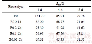
In order to characterize the stability of pre- formed SEI film, the AC impedance performance and equivalent circuit diagram of lithium electrodes with different electrolyte additives stored at room temperature for different time are researched, as show in Figure 4. Normally, the high frequency semicircle relates to Li+ ion migration through the SEI film, and the low frequency semicircle relates to charge transfer (probably across the passive film) [29, 30]. Table 2 displays interfacial resistance (Rint) for symmetric lithium cells with different electrolyte additives. It is obtained by fitting to the equivalent circuit model (Figure 4(d)). Approximately, it corresponds to the width of the semicircle in the Nyquist diagram. As shown in Figure 4 and Table 2, the interfacial resistances of lithium electrodes with different electrolyte additives display obvious change in the first 4 d and then become constant gradually. This phenomenon may be relative to the madefaction property and SEI film of lithium electrodes [8]. The lithium electrodes have not been fully infiltrated in the first several hours, leading to the high values of interfacial resistance at 1 d. After that, the decline of impedance can be ascribed to the complex reaction between the lithium electrodes and the electrolyte to form SEI film. After the relatively stable SEI film was formed, the value of Rint becomes constant. According to Table 2, the interfacial resistance of lithium electrode with no additive has the highest value, while the lithium electrode with E0.05-Cs as electrolyte has the lowest value of Rint. According to the result of this experiment, it is concluded that the higher the concentration of Cs+ ion, the higher the interfacial impedance of lithium electrode. Hence, the one reason of Li–Cu Cell with E0.05-Cs as electrolyte obtains the best Coulombic efficiency and the smallest polarization can attribute to its lowest interfacial resistance.

Figure 4 Nyquist plots obtained from impedance spectroscopy for symmetric lithium cells with different electrolyte additives as function of time:(The impedance spectroscopy results are fitted with equivalent circuit model comprising of a bulk impedance, interfacial resistance and a solid state diffusion element [10])
Table 2 Interfacial resistance for symmetric lithium cells with different electrolyte additives as a function of time
In order to check whether Cs+ ion was reduced or not during charge and discharge process, cyclic voltammogram experiments were performed in the corresponding Li–Cu cells. Figure 5 shows the CV curves of the Cu electrodes in Li–Cu cells containing different electrolyte additives. All these CV curves show similar. There is only one reduction peak, indicating that no reductive process takes place except the reduction of Li+ ion. The oxidation peaks occur above 0 V, representing the dissolution of lithium deposits. Corresponding to reduction peak, there is also one oxidation peak. Interestingly, the oxidation peak of Li–Cu cell with no electrolyte additive occurs at around 0.2 V while all oxidation peaks of Li–Cu cells with electrolyte additives occur at around 0.45 V, suggesting that the oxidation processes of Li–Cu cells with electrolyte additives are shifted to more positive potentials with respect to the basic electrolyte. According to SHES mechanism, instead of reduction, Cs+ ions are adsorbed and accumulate on the surface of lithium films in Li–Cu battery system, which could force the potential of oxidation more positive. Additionally, the increased peak current could be attributed to the smoother passive film of the lithium anode [17]. Therefore, it could be guessed that lithium deposits present more uniform in the Li–Cu cells with E0.05-Cs and E0.1-Cs as electrolytes, which can be verified in the following SEM images. Besides, as the Li–Cu cell with E0.05-Cs as electrolyte presents the best cycle performance, we can confirm the synergetic effect of Cs+ ion and NO3- ion to improve the performance of lithium anode.
Next, the deposited lithium morphologies with different concentration of CsNO3 as electrolyte additive in Li–Cu cells were investigated by 3D digital optical microscope and scanning electron microscope respectively. As depicted in Figure 6, small white points and pebble-like white areas are presented in the pictures of 3D digital optical microscopy, which may represent the needle-like lithium dendrite and non-dendrite lithium deposit respectively. This standpoint can be confirmed by the following SEM images. According to Figures 6 and 7, in the Li–Cu cell without electrolyte additive, needle-like lithium dendrite is formed on the Cu foil. This structure not only threatens the safety of battery by penetrating through the separator, but also contributes to a higher possibility of forming “dead-lithium” in the stripping process [31]. Expectedly, the smooth noodle-like lithium deposit is observed after adding 0.2 mol/L LiNO3 to electrolyte, which could indicate that the formation of lithium dendrite is efficiently suppressed. When 0.2 mol/L CsNO3 is added into the electrolyte, lithium deposits cluster together and form a big pebble-like shape. With decreasing of Cs+ ion concentration, the pebble-like lithium deposits diminish, indicating that the nucleation rates of lithium increase. Consequently, with E0.05-Cs as electrolyte, lithium deposit presents the smoothest surface, which can confirm the effect of CsNO3 to improve the deposition property of lithium anode. Additionally, EDS tests present only O element except low content of Cu element from current collector. Because of lithium foils as counter electrode in Li–Cu cells, we can conclude that the deposits are lithium.
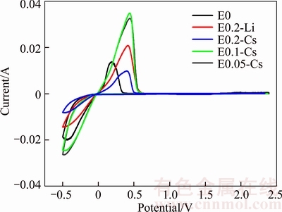
Figure 5 CV curves of Li–Cu cells containing different electrolyte additives of scan rate:10 mV/s
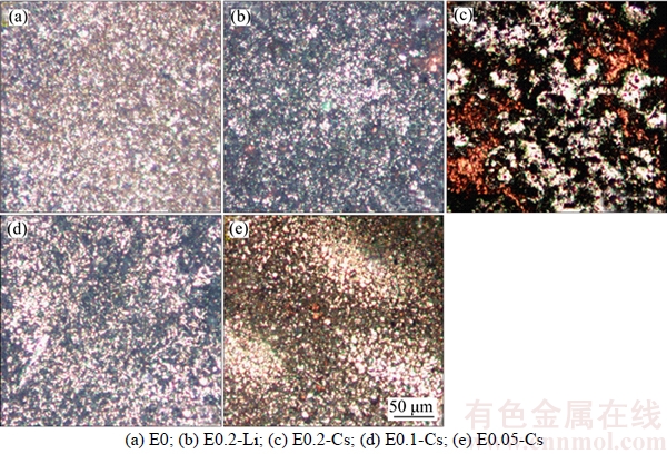
Figure 6 Three-dimensional optical views of electrochemically deposited lithium film in different additive-contained electrolytes at current density of 0.2 mA/cm2 for 5 h:

Figure 7 SEM images of electrochemically deposited lithium film in different additive-contained electrolytes at current density of 0.2 mA/cm2 for 5 h:
Finally, to evaluate the practicability of CsNO3 as electrolyte additive, the cycle performances of Li–S batteries with different electrolyte additives were tested. Figure 8 shows the discharge capacity of Li–S batteries with different electrolyte additives. The initial discharge capacities and cycle performances of Li-S batteries with E0.05-Cs and E0.2-Li as electrolyte are much higher and better than others. Expectedly, the Li–S batteries without electrolyte additive present the worst performances among these tested batteries. According to Figure 8, the discharge capacity and cycle performance of Li–S battery with E0.05-Cs as electrolyte is comparable or even superior to that with E0.2-Li as electrolyte which has been reported as excellent electrolyte additive. The advantage of CsNO3 as electrolyte additive may originate from the synergistic effect of Cs+ ion and LiNO3. Electrolyte contained appropriate concentration of Cs+ ion can prevent the forming of lithium dendrite through SHES mechanism, which has been confirmed by SEM and CV. Besides, it has been reported that LiNO3 can improve the Coulombic efficiency of Li–S battery by forming stable protective film on the lithium anode.
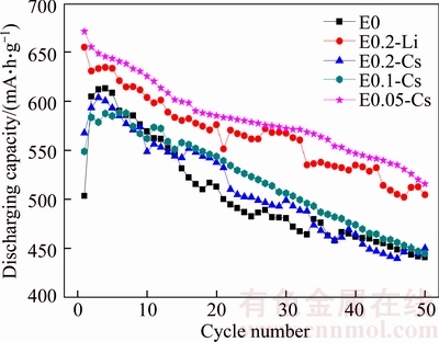
Figure 8 Discharge capacities of Li–S batteries with different additive-contained electrolytes at current density of 0.2C
From what has been discussed above, it is conclude that the electrochemical performance of battery does improve efficiently with CsNO3 as electrolyte additive. That may attribute to the synergistic effect of Cs+ and NO3-. Theoretically, Cs+ ions can form electrostatic shield on the initial growth tip of lithium dendrite and then suppress lithium dendrite formation and growth. Besides, NO3- anion can participate in forming a stable solid electrolyte interface on the lithium anode. According to the results of experiments, the cells with E0.05-Cs as electrolyte present the best electrochemical property with the highest Coulombic efficiency, the longest lifetime of strip-plate tests, the lowest interfacial resistance and the smoothest morphology of deposited lithium film. With increasing concentration of Cs+ ion in the electrolyte, the electrochemical performance of cells become poor, which might be relative to the over high concentration of Cs+ ion. With over high concentration of Cs+ ion in the electrolyte, the Cs+ ions gather on the all surface of lithium metal anode and the interfacial resistance of lithium electrode increases, which may result in poor electrochemical property.
4 Conclusions
1) With moderate CsNO3 as electrolyte additive, the Coulombic efficiency of lithium anode improves significantly and the deposited lithium morphology becomes smoother and more uniform, which is relative closely to the synergistic effect of self-healing electrostatic shield mechanism and stable SEI film formed by NO3- anion.
2) The Coulombic efficiency of lithium anode decreases with the increasing concentration of CsNO3 in the electrolyte, which might be relative to the high concentration of Cs+ ion. With increasing the concentration of Cs+ ion, the Cs+ ions appear on the all surface of lithium metal anode, which results in high interfacial resistance and uneven deposit of lithium film.
3) Lithium anode with E0.05-Cs as electrolyte has the best effective suppression on the growth of lithium dendrite, which presents the best cycle performance and the highest Coulombic efficiency of around 93% at the current density of 0.5 mA/cm2.
References
[1] QIAN Jiang-feng, XU Wu, BHATTACHARYA P, ENGELHARD M, HENDERSON W A, ZHANG Yao-hui, ZHANG Ji-guang. Dendrite-free Li deposition using trace-amounts of water as an electrolyte additive [J]. Nano Energy, 2015, 15: 135-144.
[2] WANG Dong, ZHANG Wei, ZHENG Wei-tao, CUI Xiao-qiang, ROJO T, ZHANG Qiang. Towards high-safe lithium metal anodes: Suppressing lithium dendrites via tuning surface energy [J]. Advanced Science, 2017, 4(1): 1600168.
[3] CHENG Xin-bing, ZHANG Rui, ZHAO Chen-zi, WEI Fei, ZHANG Ji-guang, ZHANG Qiang. A review of solid electrolyte interphases on lithium metal anode [J]. Advanced Science, 2016, 3(3): 1500213.
[4] SHUAI Yi, LIN Hua, CHEN Kang-hua, CHEN Song-yi, HE Xuan, GE Ke, LI Na, GAN Fang-yu. The effects of carbon-modified electrode on stability of lithium metal deposition with high areal capacity and high Coulombic efficiency [J]. Materials Letters, 2017, 209: 71-74.
[5] CHEN Xin-bing, HOU Ting-zheng, ZHANG Rui, PENG Hong-jie, ZHAO Chen-zi, HUANG Jia-qi, ZHANG Qiang. Dendrite-free lithium deposition induced by uniformly distributed lithium-ions for efficient lithium metal batteries [J]. Advanced Materials, 2016, 28(15): 2888-2895.
[6] GUO Jing, WEN Zhao-yin, WU Mei-fen, JIN Jun, LIU Yu. Vinylene carbonate-LiNO3: A hybrid additive in carbonic ester electrolytes for SEI modification on Li metal anode [J]. Electrochemistry Communications, 2015, 51: 59-63.
[7] LIU Sheng, LI Guo-ran, GAO Xue-ping. Lanthanum nitrate as electrolyte additive to stabilize the surface morphology of lithium anode for lithium-sulfur battery [J]. Acs Applied Materials and Interfaces, 2016, 8(12): 7783-7789.
[8] YOON S, LEE J, KIM S O, SOHN H J. Enhanced cyclability and surface characteristics of lithium batteries by Li–Mg co-deposition and addition of HF acid in electrolyte [J]. Electrochimica Acta, 2008, 53(5): 2501-2506.
[9] ZHANG S S. Role of LiNO3 in rechargeable lithium/sulfur battery [J]. Electrochimica Acta, 2012, 70(6): 344-348.
[10] CHOUDHURY S, ARCHER L A. Lithium fluoride additives for stable cycling of lithium batteries at high current densities [J]. Advanced Electronic Materials, 2016, 2(2): 1500246.
[11] STARK J K, DING Y, KOHL P A. Dendrite-free electrodeposition and reoxidation of lithium-sodium alloy for metal-anode battery [J]. Journal of the Electrochemical Society, 2011, 158(10): A1100-A1105.
[12] KOMABA S, ITABASHI T, KAPLAN B, GROULT H, KUMAGAI N. Enhancement of Li-ion battery performance of graphite anode by sodium ion as an electrolyte additive [J]. Electrochemistry Communications, 2003, 5(11): 962-966.
[13] ISHIKAWA M, MORITA M, MATSUDA Y. In situ scanning vibrating electrode technique for lithium metal anodes [J]. Journal of Power Sources, 1997, 68(2): 501-505.
[14] MATSUDA Y. Behavior of lithium/electrolyte interface in organic solutions [J]. Journal of Power Sources, 1993, 43(1–3): 1-7.
[15] XU Wu, HU Jian-zhi, ENGELHARD M H, TOWNE S A, HARDY J S, XIA Jie, FENG Ju, HU M Y, ZHANG Jian, DING Fei, GROSS M E, ZHANG Ji-guang. The stability of organic solvents and carbon electrode in nonaqueous Li-O2 batteries [J]. Journal of Power Sources, 2012, 215: 240-247.
[16] KOMABA S, KAPLAN B, OHTSUKA T, KATAOKA Y, KUMAGAIL N, GROULT H. Inorganic electrolyte additives to suppress the degradation of graphite anodes by dissolved Mn(II) for lithium-ion batteries [J]. Journal of Power Sources, 2003, 119(6): 378-382.
[17] LIANG Xiao, WEN Zhao-yin, LIU Yu, WU Mei-fen, JIN Jun, ZHANG Hao, WU Xiang-wei. Improved cycling performances of lithium sulfur batteries with LiNO3- modified electrolyte [J]. Journal of Power Sources, 2011, 196: 9839-9843.
[18] DING Fei, XU Wu, GRAFF G L, ZHANG Jian, SUSHKO M L, CHEN Xi-lin, SHAO Yu-yan, ENGELHARD M H, NIE Zi-min, XIAO Jie, LIU Xing-jiang, SUSHKO P V, LIU Jun, ZHANG Ji-guang. Dendrite-free lithium deposition via self-healing electrostatic shield mechanism [J]. Journal of the American Chemical Society, 2013, 135(11): 4450-4456.
[19] DING Fei, XU Wu, CHEN Xi-lin, ZHANG Jian, SHAO Yu-yan, ENGELHARD M H, ZHANG Yao-hui, BLAKE T A, GRAFF G L, LIU Xing-jiang, ZHANG Ji-guang. Effects of cesium cations in lithium deposition via self-healing electrostatic shield mechanism [J]. Journal of Physical Chemistry C, 2014, 118(8): 4043-4049.
[20] XIONG Shi-zhao, XIE Kai, HONG Xiao-bin. Effect of LiNO3 as additive on electrochemical properties of lithium-sulfur batteries [J]. Chemical Journal of Chinese Universities, 2011, 32(11): 2645-2649. (in Chinese)
[21] BARGHAMADI M, BEST A S, HOLLENKAMP A F, MAHON P, MUSAMEH M, R THER T. Optimising the concentration of LiNO3 additive in C4mpyr-TFSI electrolyte-based Li-S battery [J]. Electrochimica Acta, 2016, 222: 257-263.
[22] ZHANG S S. A new finding on the role of LiNO3 in lithium-sulfur battery [J]. Journal of Power Sources, 2016, 322: 99-105.
[23] ZHANG S S, READ J A. A new direction for the performance improvement of rechargeable lithium/sulfur batteries [J]. Journal of Power Sources, 2012, 200(1):77-82.
[24] ZHANG An-yi, FANG Xin, SHEN Chen-fei, LIU Yi-hang, ZHOU Chong-wu. A carbon nanofiber network for stable lithium metal anodes with high Coulombic efficiency and long cycle life [J]. Nano Research, 2016, 9(11): 3428-3436.
[25] JIA Wei-shang, FAN Cong, WANG Li-ping, WANG Qing-ji, ZHAO An-jun, LI Jing-ze. Extremely accessible potassium nitrate (KNO3) as the highly efficient electrolyte additive in lithium battery [J]. Acs Applied Materials and Interfaces, 2016, 8: 15399-15405.
[26] ZHENG Guang-yuan, LEE S W, LIANG Zheng, LEE H W, YAN Kai, YAO Hong-bin, WANG Hao-tian, LI Wei-yang, CHU S, CUI Yi. Interconnected hollow carbon nanospheres for stable lithium metal anodes [J]. Nature Nanotechnology, 2014, 9(8): 618-623.
[27] LUO Wei, ZHOU Li-hui, FU Kun, YANG Zhi, WAN Jia-yu, MANNO M, YAO Yong-gang, ZHU Hong-li, YANG Bao, HU Liang-bing. A thermally conductive separator for stable Li metal anodes [J]. Nano Letters, 2015, 15: 6149-6154.
[28] QIAN Jiang-feng, HENDERSON W A, XU Wu, BHATTACHARYA P, ENGELHARD M, BORODIN O, ZHANG Ji-guang. High rate and stable cycling of lithium metal anode [J]. Nature Communications, 2015, 6: 6362.
[29] AURBACH D, GAMOLSKY K, MARKOVSKY B, GOFER Y, SCHMIDT M, HEIDER U. On the use of vinylene carbonate(VC) as an additive to electrolyte solutions for Li-ion batteries [J]. Electrochimica Acta, 2002, 47(9): 1423-1439.
[30] ZHOU Hong-ming, GENG Wen-jun, LI Jian. LiPF6 and lithium difluoro(oxalate)borate/ethylene carbonate+dimethyl carbonate+ethy(methyl)carbonate electrolyte for LiNi0.5Mn1.5O4 cathode [J]. Journal of Central South University, 2017, 24: 1013-1018.
[31] VAUGHEY J T, LIU Gao, ZHANG Ji-guang. Stabilizing the surface of lithium metal [J]. MRS Bulletin, 2014, 39(5): 429-435.
(Edited by YANG Hua)
中文导读
电解液添加剂CsNO3对锂金属负极电化学性能的影响
摘要:锂金属因具有高理论能量密度而成为理想的电池负极材料之一,但其在实际应用过程中主要存在两个问题:锂枝晶的生长和低库伦效率。为解决这一问题,硝酸铯(CsNO3)被选为添加剂加入电池电解液中,研究含不同浓度CsNO3的电解液对锂二次电池电化学性能的影响。研究结果表明,电解液中添加CsNO3后Li–Cu电池的库伦效率得到显著提高,循环寿命得到延长。当电解液中含0.05 mol/L CsNO3和0.15 mol/L LiNO3时,Li–Cu电池具有最佳的电化学性能,库伦效率高达97%,并具有最低的界面阻抗。随着电解液中CsNO3浓度的提高,电池的电化学性能逐渐下降。此外,锂的沉积形貌在含CsNO3电解液中比在无添加剂电解液中更为圆润、均匀。
关键词:硝酸铯;锂负极;电解液添加剂;库伦效率;电化学性能;微观形貌
Foundation item: Project(2016YFB0300801) supported by the National Key Research and Development Program of China; Project(2012CB619502) supported by the National Basic Research Program of China
Received date: 2016-09-06; Accepted date: 2018-01-20
Corresponding author: CHEN Kang-hua, PhD, Professor; Tel: +86–13574189084; E-mail: khchen@csu.edu.cn

