Article ID: 1003-6326(2005)03-0529-07
Phase-field simulation of formation of cellular dendrites and fine cellular structures at high growth velocities during directional solidification of Ti56Al44 alloy
LI Xin-zhong(������), GUO Jing-jie(������), SU Yan-qing(������),
WU Shi-ping(��ʿƽ), FU Heng-zhi(����־)
(School of Materials Science and Engineering, Harbin Institute of Technology,
Harbin 15001, China)
Abstract: A phase-field model whose free energy of the solidification system derived from the Calphad thermodynamic modeling of phase diagram was used to simulate formation of cellular dendrites and fine cellular structures of Ti56Al44 alloy during directional solidification at high growth velocities. The liquid-solid phase transition of L���� was chosen. The dynamics of breakdown of initially planar interfaces into cellular dendrites and fine cellular structures were shown firstly at two growth velocities. Then the unidirectional free growths of two initial nucleations evolving to fine cellular dendrites were investigated. The tip splitting phenomenon is observed and the negative temperature gradient in the liquid represents its supercooling directional solidification. The simulation results show the realistic evolution of interfaces and microstructures and they agree with experimental one.
Key words: phase-field simulation; directional solidification; Ti56Al44 alloy CLC
number: TG248; TG244 Document code: A
1 INTRODUCTION
Over the last ten years the phase field method has been extensively used to simulate the formation of solidification morphology because of its benefit of avoiding the explicit boundary tracking needed to solve the classical sharp interface model. The first model for alloy solidification was proposed by Wheeler et al[1], widely called WBM model. The WBM model has been most extensively used in ideal solutions of binary alloys[2-6]. Recently, Kim et al[7] proposed a new phase-field model for binary alloys, named KKS model, which is equivalent to the WBM model, but has a more appropriate definition of the free energy density for the interfacial region[7]. Presently, the KKS model has been widely used to simulate microstructure evolution in solidification of dilute solutions[8]. Using phase-field models, Boettinger and Warren[9] studied the transition from the cell to plane during directional solidification at high growth velocities with the frozen temperature approximation, and Zhang and Sekerka[10] investigated the transition between a planar interface and steady shallow cells near the onset of morphological instability at low growth velocities. Furthermore, Lan and Chang[11] conducted an efficient adaptive phase-field simulation based on a finite volume method to study the morphological development during directional solidification, which allowed the calculation to cover different length scales for the interface, solute diffusion and heat conduction. However, the simulations of metal alloys are seldom about formation of cellular dendrites and its transition to fine cellular structures at a growth velocity, which is sufficiently higher than the critical velocity of transition from cells to dendrites, but lower than the absolute stability.
In this paper, formation of cellular dendrites and fine cellular structures of Ti56Al44 alloy during directional solidification was investigated at high growth velocities using the phase-field method. The liquid-solid transition of L���� was chosen. In present simulation, a phase-field model was adopted whose free energy densities of solid and liquid were derived from a Calphad thermodynamic modeling of phase diagram, which comprehensively considered WBM model and KKS model as the one described in Ref.[13].
2 PHASE-FIELD MODEL
The basic derivation of the phase-field model can be found in Ref.[13]. And its detailed application to simulation of Ti-Al alloy microstructures can be seen in Ref.[14]. The main equations of this model can be written as
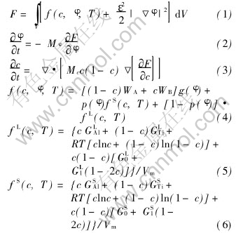
where F is the Gibbs free energy for a solidification system, V is the volume of the system, f(c, ��, T) is the free energy density, c is the solute composition, �� is the phase field, T is the temperature, �� is the gradient energy coefficient, M��, Mc, WA, WB are phase-field parameters derived like in Refs.[13, 14], g(��)=��2(1-��)2 and p(��)=��3(10-15��+6��2) are chosen, where ��=0 represents liquid and ��=1 represents solid, GLAl, GLTi, GSAl, GSTi, GL0, GL1, GS0 and GS1 are thermodynamic data of Ti-Al alloy, Vm is the molar volume.
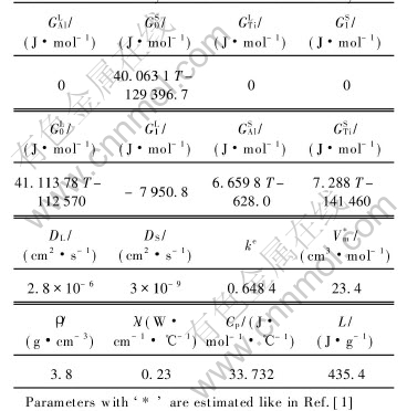
The thermodynamic data of Ti56Al44 alloy and other calculation parameters are listed in Table 1.
Table 1 Thermodynamic data of Ti-Al alloy[10, 12]
3 NUMERCIAL ISSUE
The finite difference method was used to solve the above phase field equations on uniform grids. Firstly, the breakdown of initial planar interfaces into cellular dendrites was investigated. The simulations were conducted in a box with the size of (1.92��10-2cm)��(1.44��10-2cm) (4000��3000 mesh). The constant temperature gradient of 800K/cm, the reference temperature of 1810K and the growth velocities of 0.005cm/s (lower than the absolute stability of 2.88cm/s estimated according to LIU[15]) were taken. Then at a higher growth velocity of 1.25cm/s and under the same other conditions with the above simulation, formation of fine cellular structures in a box of (1.152��10-2cm)��(1.152��10-2cm) (2400��2400 mesh) was investigated. In addition, a moving grid algorithm was implemented in these two simulations, which adapted the computation domain to moving solid-liquid interface to save computational time like in Refs.[9, 11]. Finally formation of cellular dendrites during the unidirectional solidification with the boundary heat exchange of ��[SX(]��T[]��n[SX)]=Q was studied, where Q is the heat exchange flux taken 54.2W/cm2 and 72W/cm2, �� is thermal conductivity. And only two initial nucleations appeared in a supercooling melt with an initial temperature of 1802K just like in many supercooling directional solidifications[16, 17]. The simulations were conducted in a box of (1.44��10-2cm)��(1.44��10-2cm) (3000��3000 mesh).
4 RESULTS AND DISCUSSION
Fig.1 shows a sequence of six time slices obtained from the simulation at a growth velocity of 0.005cm/s. The composition field is shown. In the reference frame, the initially solid-liquid interface falls back and breaks down when the interface perturbations caused by the noise begin to amplify. Soon, many cells are formed(Fig.1(a)). These cells will grow competitively, some of which are swallowed and the others survive(Fig.1(b)). The survived cells coarse gradually, and also have to go through the competitive growth continuously with adjacent ones until the formation of stable cells(Figs.1(c)-(d)). As the growth of these stable cells, side arms appear near some of theirs�� tips(Fig.1(e)). These arms will advance and cellular dendrites are formed(Fig.1(f)). The solute build-up in the liquid ahead of the solid-liquid interface and micro-segregation patterns can be observed clearly.
Fig.2 shows the simulation result at a high growth velocity of 1.25cm/s. The increase of growth velocity causes the reduction of wavelength of perturbations, but the amplitude increases. So the solid-liquid interface breaks down with many fine cells, and these cells will grow competitively and drastically in a long distance, which causes the
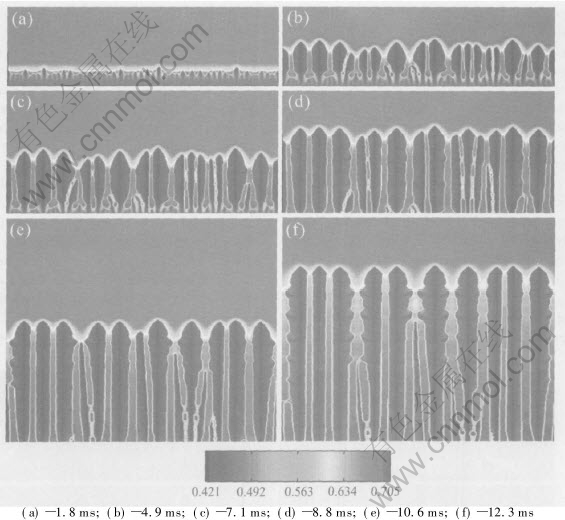
Fig.1 Simulation result of formation of cellular dendrite structure at 0.005cm/s
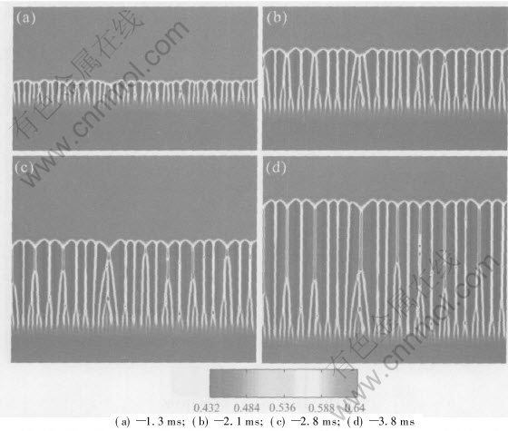
Fig.2 Simulation result of formation of fine cellular structures at 1.25cm/s
liquid pocket shed from the root region of the cells and these pockets subsequently freeze leading to the location of high microsegregation. Finally a fine cellular structure is produced. Compared with Fig.1, present one shows a finer cellular structure, that is, more survived cells, weaker microsegregation and thinner solute diffusion layer at the interface, which implicates a transition from cellular dendrites to fine cellular structures due to increase of growth velocity during directional solidification.
Fig.3 shows the simulation result during the unidirectional solidification with the boundary heat exchange flux of 54.2W/cm2, which shows the formation of cellular dendrites by composition field. The initial nucleations with an initial distance of 54��m grow preferably into two directions. One is inside of melt and the other is two lateral sides. Because the bottom is continuously cooled, the growth rate of the latter is larger than that of the former (Fig.3(a)). Soon, secondary arms appear due to unstable interface (Fig.3(b)), and the secondary arms growing to inside of melt and two lateral sides will advance and begin to grow competitively (Fig.3(c)). Then, some secondary arms growing to inside of melt will survive and develop to steady-growth cells, named survived cells, which restrains the development of the secondary arms of leading arms to lateral sides (Figs.3(d)-(e)). Some survived cells even evolving to dendrites can also be observed. Finally, the concurrent growth of cells and dendrites appear (Fig.3(f)), that is, the formation of a fine cellular dendrite. The build-up of solute in the liquid ahead of the interface and micro-segregation patterns can be seen clearly. Fig.4 shows the simulation results with a bigger heat exchange flux of 72W/cm2 and the initial distance of 72��m between two nuclea-
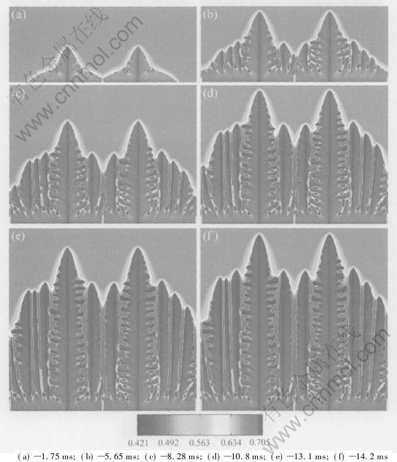
Fig.3 Simulation result of formation of cellular dendrite structure at 54.2W/cm2 in boundary
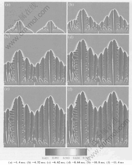
Fig.4 Simulation result of formation of cellular dendrite structure at 72W/cm2 in boundary
tions. Slighter dendritic structures and smaller cell spacing are observed clearly. The tips of the leading arms split to form fine cellular dendrite, which indicates the selection of arm spacing and can be often observed in directional solidification experiment.
Fig.5 shows the temperature field corresponding to the solid-liquid interface after a solidification time of 11.4ms in Fig.4(f). It can be seen that the spatial temperature difference in this system is only 2.6K, the increase of melt temperature doesn��t exceed 3K due to the latent heat generation, the hottest point appears in the liquid near the survived cell tips because of the continuously competitive growth between the advancing secondary arms of leading arms and the survived cell tending to form closet pockets, and the coldest temperature is lower only about 0.28K than initial melt temperature because of small heat exchange flux used at bottom. Fig.6 shows the temperature profile at five time slices along the leading arm, which represents the present solidification can be regard as supercooling directional solidification[16, 17] because of negative temperature gradient in the liquid ahead of the leading tip.
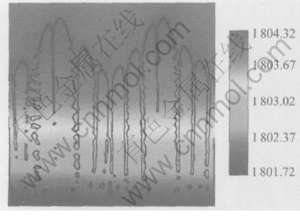
Fig.5 Temperature field corresponding to solid-liquid interface after solidification time of 11.4ms in Fig.4(f)
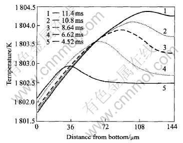
Fig.6 Temperature profile along leading arm at five time slices in Fig.4(f)
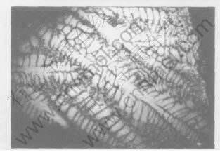
Fig.7 Dendritic morphology derived from experiment of directional solidification of Ti-44%Al(mole fraction) alloy
Fig.7 shows the dendritic morphology derived from the experiment of directional solidification of Ti56Al44 alloy[18]. Some kinds of similarities can be derived from Figs.3 and 4, though growth conditions are slightly different.
5 CONCLUSIONS
1) The formation of cellular dendrites and fine cellular structures of Ti55Al44 alloy during directional solidification at high growth velocities are simulated using a phase field model whose free energy of the solidification system is derived from the Calphad thermodynamic modeling of phase diagram. Realistic evolution of interfaces and microstructures at different growth velocities are derived.
2) During directional solidification at a growth velocity, which is sufficiently higher than the critical velocity of transition from plane to cell, but lower than the absolute stability, initially planar interface will break down into cellular structures, then cellular dendrites. The increase of growth velocity will cause the transition from cellular dendrites to fine cellular structures.
3) During the unidirectional free growth with the boundary heat exchange flux, the concurrent structures of cells and dendrites are observed and bigger heat exchange flux will cause slighter dendritic structures and smaller cell spacing. Tip splitting phenomenon shows the selection of arm spacing. There exists the negative temperature gradient in the liquid ahead of leading arm tip and it can be seen as supercooling directional solidification and some kinds of similarities can be derived with the experimental results of directional solidification.
REFERENCES
[1]Wheeler A A, Boettinger W J, McFadden G B. Phase-field model for isothermal transition in binary alloys[J]. Phys Rev A, 1992, 45: 7424-7439.
[2]Warren J A, Boettinger W J. Prediction of dendritic growth and microsegregation patterns in a binary alloy using the phase-field method[J]. Acta Metall Mater, 1995, 43: 689-703.
[3]Wheeler A A, Boettinger W J, McFadden G B. Phase-field model of solute trapping during solidification[J]. Phys Rev E, 1993, 47: 1893-1909.
[4]Ahmad N A, Wheeler A A, Boettinger W J, et al. Solute trapping and solute drag in a phase-field model of rapid solidification[J]. Phys Rev E, 1998, 58: 3436-3450.
[5]Loginova I, Amberg G, Agren J. Phase-field simulation of non-isothermal binary alloy solidification[J]. Acta Mater, 2001, 49: 573-581.
[6]George W L, Warren J A. A parallel 3D dendritic growth simulator using the phase-field method[J]. Journal of Computational Physics, 2002, 177: 264-283.
[7]Kim S G, Kim W T, Suzuki T. Phase-field model for binary alloys[J]. Phys Rev E, 1999, 60: 7186-7197.
[8]Suzuki T, Ode M, Kim S G, et al. Phase-field model of dendritic growth[J]. J Crystal Growth, 2002, 237: 125-131.
[9]Boettinger W J, Warren J A. Simulation of the cell to plane front transition during directional solidification at high velocity [J]. J Cryst Growth, 1999, 200: 583-591.
[10]Zhang B, Sekerka R F. Phase field modeling of shallow cells during directional solidification of a binary alloy[J]. J Crystal Growth, 2002, 237: 138-143.
[11]Lan C W, Chang Y C. Efficient adaptive phase field simulation of directional solidification of a binary alloy[J]. J Crystal Growth, 2003, 250: 525-537.
[12]Zhang F, Chen S L, Chang Y A. Thermodynamic stability and point defects of ��-TiAl and the phase relationships of Ti-Al[J]. The Minerals Metals Materials Society, 1995, 13: 131-140.
[13]Boettinger W J, Warren J A, Beckermann C, et al. Phase field simulation of solidification[J]. Annu Rev Mater Res, 2002, 32: 163-194.
[14]GUO Jing-jie, LI Xin-zhong, SU Yan-qing. Phase-field simulation of structure evolution at high growth velocities during directional solidification of Ti55Al45 alloy[J]. Intermetallics, 2005, 13: 275-279.
[15]LIU Yong-chang. Phase Selection and Controlling in Rapidly Solidification Ti-Al Peritectic Alloy [D]. Xi��an: Northwestern Polytechnical University, 2000.
[16]XIE Fa-qin, JUN Zhang, MAO Xie-min, et al. Rapid directional solidification excited from bulk supercooled melt[J]. J Mater Pro Tech, 1997, 63: 776-778.
[17]FU Heng-zhi, XIE Fa-qin. The solidification characteristics of near rapid and supercooling directional solidification[J]. Science and Technology of Advanced Materials, 2001, 2: 193-196.
[18]Jung I S, Kim M C, Lee J H, et al. High temperature phase equilibria near Ti-50at%Al composition in Ti-Al system studied by directional solidification[J]. Intermetallics, 1999, 7: 1247-1253.
(Edited by LI Xiang-qun)
Foundation item: Projects(50391012; 50271020) supported by the National Natural Science Foundation of China
Received date: 2004-11-24; Accepted date: 2005-03-14
Correspondence: LI Xin-zhong, PhD; Tel: +86-451-86418815; E-mail: uniquelxz@hit.edu.cn

