Trans. Nonferrous Met. Soc. China 23(2013) 2187-2193
3D finite element numerical simulation of advanced detection in roadway for DC focus method
Xiao-kang DENG1,2, Jian-xin LIU1,2, Hai-fei LIU1, Xiao-zhong TONG1, Zhou LIU1
1. School of Geosciences and Info-physics, Central South University, Changsha 410083, China;
2. Key Laboratory of Nonferrous Resource and Geological Hazard of Hunan Province, Changsha 410083, China
Received 26 March 2013; accepted 22 May 2013
Abstract: Within the roadway advanced detection methods, DC resistivity method has an extensive application because of its simple principle and operation. Numerical simulation of the effect of focusing current on advanced detection was carried out using a three-dimensional finite element method (FEM), meanwhile the electric-field distribution of the point source and nine-point power source were calculated and analyzed with the same electric charges. The results show that the nine-point power source array has a very good ability to focus, and the DC focus method can be used to predict the aquifer abnormality body precisely. By comparing the FEM modelling results with physical simulation results from soil sink, it is shown that the accuracy of forward simulation meets the requirement and the artificial disturbance from roadway has no impact on the DC focus method.
Key words: roadway; DC focus; advanced detection; finite element method
1 Introduction
With the construction of high speed railway, highway and submarine tunnel, geologic disasters always play a main threat on the safety of tunnel and underground engineering construction. For these geologic disasters, underground water plays an important role. For example, karst cave, underground river, karst sink hole, karst muddy belts, water-saturated and fracture zone [1], all these can cause difficulty and harmness on the construction and operation of tunnel and underground engineering. Tunnel geological hazard forecasting plays an important role in avoiding these geological hazards. Presently, there are many methods used in the field of tunnel geological hazard forecasting and these methods have their own advantages and applications. But there are some unsolved problems in the exploration of unfavorable geology body in tunnel filled with water which is the main point of this study [2,3].
In recent years, a great progress has been made in advanced detection technology, and a bunch of advanced detection methods have been developed, such as seismic reflection method, Rayleigh wave method, DC resistivity method and ground penetrating radar method, meanwhile their instruments have been developed, which makes an important contribution to predicting the underground geological disasters [4-9]. A new method, i.e., DC focus method for advanced detection is proposed and developed in roadways, and simulated several tunnel models under the focus surveying condition using a 2-D finite element method for anomaly potentials [10-12]. The modelling results show that this method can be used to model the anomaly. ZHOU et al [13] and YANG et al [14] carried out clay testing and conductive paper testing respectively for the focus advanced detection method to demonstrate its feasibility. QIANG et al [15] and RUAN et al [16] developed three kinds of electrode combinations, e.g., four-point power source, five-point power source and nine-point power source. In addition, the potential distributions of the three electrode systems are calculated by 3D FEM, and the nine point power source mode has a good current focusing performance. It is shown that when the main electrode current is less than the shield electrode current, the focusing effect is the best. Finite element numerical method is used to simulate the advanced detection in 3D roadway space for DC focus method. Compressed storage technology and preconditioned iterative algorithm significantly improves the efficiency of forward modelling.
In this work, 3D finite element method was used to simulate the effect of focused advanced detection, and calculate and analyze the electric-field distribution of the point source and nine-point power source with the same electric charge.
2 DC focus method
In the DC focus method, shielding electrodes are placed around power supply electrodes, which forces the electric field of power supply electrodes to have certain direction, achieving focusing current, removing the side anomalous body interference. In order to achieve the current focus, electrode arrangement is set to be circular, polygonal or other shape, as shown in Fig. 1(a). Nine- point power source shown in Fig. 1(b) is adopted. Shielding electrode beam A and potential electrode beam M1-M4 are symmetrically distributed in the working square face and power supply electrode A0 is located at the centre of shielded electrode beam and measuring electrode beam. B pole and N pole are arranged at infinity beyond roadway. Shielding electrode beam and power supply electrode respectively supply a current of 1 A at the same time and any potential electrode of M1-M4 can be used as recievers, or all of them are simultaneously used.
3 3D finite element numerical simulation method
The basic equation of point source electric potential in the steady current field is given by Eq. (1).
 (1)
(1)
where σ is the conductivity; u is the electric potential and j is the current density. After making some transformation on Eq. (1), a 3D differential equation is obtained according to the integral of function δ in half space as

 (2)
(2)
The boundary conditions of 3D electric field are
 (3)
(3)
The equivalent variation problem is
 (4)
(4)
where I is the electric current; n is the direction of the outer normal line in the boundary; Γs is the interface between the medium and air; r is the radius vector from the source point to a boundary point; Γ∞ means infinitely far away from the source; Ω is the mesh area and Γ is the boundary.
The whole area is divided into two parts as shown in Fig. 2, one is the target area, the other is the mesh boundary area. The target body is located in an area near the roadway and a uniform mesh subdivision pattern is used. The grid boundary area is used to improve the precision of numerical simulation. Small to large uneven subdivisions are used to simulate the infinite boundary and the mesh size changes in Fibonacci sequences.

Fig. 1 Schematic diagrams of working face electrode arrangement

Fig. 2 Schematic diagram for finite element mesh
In order to improve the near field source potential calculation accuracy, an abnormal potential finite element method is adopted. Firstly, hexahedral elements are used to divide area Ω, and the integral is decomposed into sum of each unit; secondly, without losing the calculation precision, the integral equation is simplified by homogeneous boundary condition to improve the calculation efficiency. From each sub-element integral, a linear system equation is obtained.
Ku=-K′u0 (5)
where K and K′ denote the coefficient matrices; u denotes the calculated abnormal potential column vector and u0 denotes the normal potential column vector. By solving Eq. (5), the abnormal potential value of each node is achieved.
4 Electric potential distribution of DC focus method
In order to examine the validity of focusing current method, the focusing current field and point source field distribution is calculated. In this model, the resistivity of exterior medium beyond the roadway is 1000 Ω・m, and the cross section size of the roadway is 8 m×8 m. Both the potential distribution on X―Z cross-sections are achieved, which are shown in Fig. 3. The isoline represents equal potential, and the directions of the arrows represent the current direction. It can be seen clearly, for focusing current field, the focusing field has the mutually exclusive characteristics, which makes the current mainly flow along the excavating direction of working face. In contrast, the resulting current for a point source at Z=0 spreads out the whole area. Table 1 lists the potential value of X direction along the working face for Z=0. From the table, it can be intuitive to conclude that the potential from focusing method is far larger than that produced by the point source. Near the power supply, focusing current field produces potential values that are 3 times larger than the point source. The farther it is from the power supply, the larger the ratio of focusing current induced potential to the point source produced potential. When it is 10 m away from the power supply, the potential value produced by focusing current field is about 7 times of the potential value produced by point source field. The comparison of results clearly shows the capability of advanced detection in focusing current field.

Fig. 3 Potential distribution of field on X―Z section
Table 1 Comparison between point source potential and focusing current potential

Figure 4 shows the focusing electric current field in the tunnelling direction (X direction), when the working face is located at X=0. The potential distribution of X direction in Y―Z section for the model is shown in Fig. 3. The picture illustrates that the focusing electric field method can make the forward current focusing in the X direction, which is fundamental for its directional observation. Through the analysis of the distribution of the electric field in tunnelling direction of X―Z section and Y―Z section, it is proved that DC focus method has the ability to focus on current, and it is better than that generated by a single point source.
5 Accuracy analysis
5.1 Model 1
Model 1 shown in Fig. 5(a) is a three-layered media. The top layer has a resistivity of ρ1= 50 Ω・m and a thickness of h1=30 m. The second layer has a resistivity of ρ2= 20 Ω・m and a thickness h2=80 m. The third layer is a uniform half-space with a resistivity ρ3= 100 Ω・m. The analytical potential can be obtained by a digital linear filter, and the measured array is symmetrical four-poled. The FEM takes 566.1 s for a grid with 36×30×30=32400 nodes. Table 2 lists the comparison between the analytical solution and the potential yielded by unit current point-source using abnormal potential method. The maximal error between the analytical solution and the numerical solution is 1.6% and the average error between the analytical solution and the numerical solution is 0.5%. It can be seen that this precision can meet the requirement, as shown in Fig. 5(b).
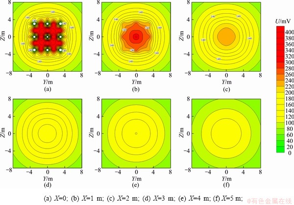
Fig. 4 Potential distribution of focusing current field on Y―Z section

Fig. 5 Comparison of analytical and numerical solution over three-layered model, source point O is located at origin of coordinate system
Table 2 Comparison between numerical and analytical solutions for Model 1

5.2 Physics experiment test
In order to verify the correctness of the method, adopted numerical simulation and physical simulation are compared, indicating the numerical simulation for the model and physical experimental results are consistent. In the experiment, the half space medium is composed of clay, roadway cross section modelled by a square with width of 14 cm and surrounding rock (uniform clay) resistivity of about 100 Ω・m. The dimensions of the soil slot size are 150 cm×120 cm×80 cm. A copper body is used as the anomaly, the dimensions are 15 cm×15 cm×0.4 cm, and its resistivity is about 1 Ω・m as shown in Fig. 6(a). When the experiment begins, the anomalous body is located far from the working face. Then, the anomalous body is moved to the woking face, d denotes the distance between the working face of roadway and the geometric-centre of the recorded abnormal body. In order to reduce the error, each survey points are repeated, with potential U measured. For the convenience of intuitive comparison, the normalized potential U/U0 is used, U0 and U represent the potential difference between the potential electrode and infinity for the model without abnormal body and potential with abnormal body in working face, respectively. Figure 6(b) shows the distribution of the normalization potential U/U0 along the excavation direction from numerical simulation and physical modelling. The results indicate that the data from finite element numerical simulation are basically consistent with the soil sink simulation data, even though some minor differences exist at one end of the curve. The results indicate that the roadway DC focus method is feasible and the simulation is reliable.
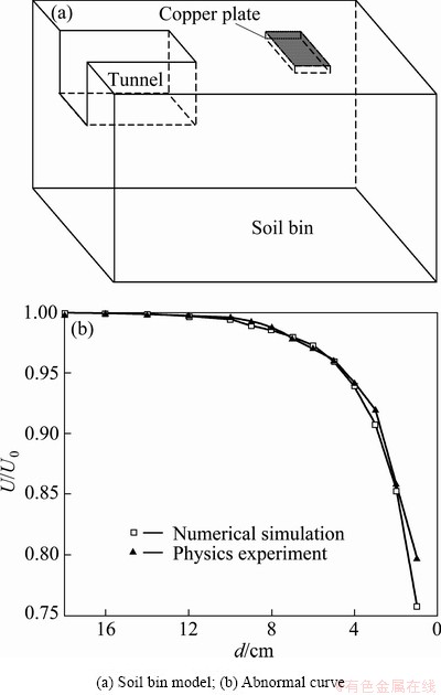
Fig. 6 Comparison between simulation and calculation results
5.3 Model 2
So far, DC focusing simulation is based on simple models without considering the interference of lateral anomalous bodies and the influence of the roadway. Simple models are usually not the case in practice, e.g., the existence of the geological body, and other anomalies, such as cavity, railway trail, transportation facility and electric wire. Therefore, the study on DC focusing interference caused by those bodies has a practical significance. The model consists of a roadway with size of 5 m×5 m, and a low resistivity body with dimensions of 6 m×5 m×2 m, resistivity of 10 Ω・m, located at a distance of 18 m before the working face. As shown in Fig. 7(a). A copper plate with dimensions of 4 m×3 m×2 m exists in the roadway, and it is located at a distance of 3 m behind the working face, with surrounding rock resistivity of 1000 Ω・m. In Fig. 7(b) there are no obvious differences in the results obtained from models with and without metal body in the heading face of roadway. The metal bodies existing in the roadway have little influence on the advanced detection.
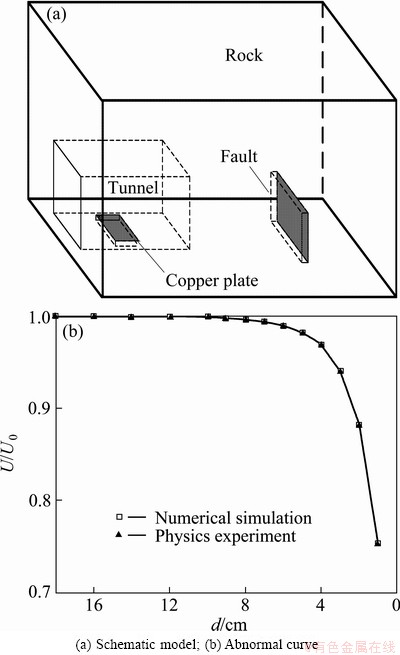
Fig. 7 Influence of metal body in tunnel
6 Conclusions
1) A 3D finite element numerical simulation was developed to understand the method of focused advanced detection.
2) The electric-field distribution of the point source and nine-point power source is calculated and analyzed with the same electric charge. The results show that the array has a very good ability on focusing and the DC focus method can precisely detect the aquifer abnormality body.
3) The comparison of FEM modelling results with physical simulation results in the soil sink shows that the accuracy of forward simulation meets the requirement and the artificial disturbance from roadway has no impact on DC focus method.
Reference
[1] SONG Xian-hai, GU Han-ming, XIAO Bo-xun. Overview of tunnel geological advanced prediction in China [J]. Progress in Geophysics, 2006, 21(3): 605-613. (in Chinese)
[2] ZENG Zhao-fa, LIU Si-xin, LIU Shao-hua. The new progress of environmental and engineering geophysics [J]. Progress in Geophysics, 2004, 19(3): 486-491. (in Chinese)
[3] ZHAO Yong-gui, LIU Hao, SUN Yu, XIAO Kuan-huai. Research progress in tunnel geological prediction [J]. Progress in Geophysics, 2003, 18(3): 460-464. (in Chinese)
[4] LI Yong-hong, XU Guang-ling, YANG Yin-hu. Application of seismic reflected wave method to geological prediction for tunnelling [J]. Chinese Journal of Geotechnical Engineering, 2005, 27(10): 1180-1184. (in Chinese)
[5] ZENG Zhao-huang. Prediction ahead of the tunnel face by the seismic reflection methods [J]. Chinese J Geophys, 1994, 37(2): 218-230. (in Chinese)
[6] HE Zhen-qi, LI Hai, LIANG Yan-zhong. Geological super-leading forecast during tunnel construction by utilizing seismic response analysis method [J]. Journal of Railway Engineering Society, 2000, 68(4): 81-85. (in Chinese)
[7] LU Guang-yin, ZHU Zi-qiang. Application of TSP in the expressway tunnel geological prediction [J]. Hydrogeology and Engineering Geology, 2005, 2(5): 101-103. (in Chinese)
[8] TAN Jin-long, CHEN Yao-chan, LIU Ji. Application of transient surface wave exploration technology for forecast in tunnel engineering [J]. Soil Eng and Foundation, 2005, 19(4): 86-90. (in Chinese)
[9] HUANG Jun-ge, WANG Jia-lin, RUAN Bai-yao. A study on advanced detection using DC resistivity method in tunnel [J]. Chinese J Geophys, 2006, 49(5): 1529-1538. (in Chinese)
[10] RUAN Bai-yao, DENG Xiao-kang, LIU Hai-fei, ZHOU Li, ZHANG Li. Research on a new method of advanced focus detection with DC resistivity in tunnel [J]. Chinese J Geophys, 2009, 52(1): 289-296. (in Chinese)
[11] RUAN Bai-yao, DENG Xiao-kang, LIU Hai-fei, ZHOU Li, ZHANG Li. The influential factor and optimum surveying method of advanced focus detection with DC resistivity in tunnel [J]. Progress in Geophysics, 2010, 25(4): 1380-1386. (in Chinese)
[12] LIU Jian-xin, DENG Xiao-kang, GUO Rong-wen, LIU Hai-fei, TONG Xiao-zhong, LIU Zhou. Numerical simulation of advanced focus detection with DC resistivity in tunnel by the finite element method [J]. The Chinese Journal of Nonferrous Metals, 2012, 22(3): 970-975. (in Chinese)
[13] ZHOU Li, RUAN Bai-yao, NING Shao-qiu, DUAN Chang-sheng. Model experiment of focused current method in advanced tunnel detection [J]. Journal of Guilin University of Technology, 2009, 29(1): 40-42. (in Chinese)
[14] YANG Ting-wei, RUAN Bai-yao, ZHOU Li, DUAN Chuang-sheng. Simulating focused-current advanced detection in tunnels by conductive paper test [J]. Mineral Resources and Geology, 2009, 23(4): 362-366. (in Chinese)
[15] QIANG Jian-ke, RUAN Bai-yao, ZHOU Jun-jie. Research on the array of electrodes of advanced focus detection with 3D DC resistivity in tunnel [J]. Chinese J Geophys, 2010, 53(3): 695-699. (in Chinese)
[16] RUAN Bai-yao, QIANG Jian-ke, ZHOU Jun-jie. The theory of three-dimensional DC focusing resistivity technique in tunnel advanced exploration [J]. Geophysical & Geochemical Exploration, 2009, 33(6): 729-732. (in Chinese).
巷道聚焦电流法超前探测的三维有限元数值模拟
邓小康1,2,柳建新1,刘海飞1,童孝忠1,柳 卓1
1. 中南大学 地球科学与信息物理学院,长沙 410083;
2. 中南大学 有色资源与地质灾害探查湖南省重点实验室,长沙 410083
摘 要:在巷道超前探测的方法中,电阻率法由于原理简单、操作方便,有着很好的应用前景。运用三维有限元法对聚焦电流法的超前预报效果进行数值模拟,计算和分析点电源和九点式电源在供相同电流的情况下电场的分布情况。结果表明:九点式布极方式有很好的聚焦能力,聚焦电流法能准确地发现掘进面前方含水异常体。将数值模拟和物理土槽试验进行对比,正演模拟精度符合要求,巷道中的人为干扰对聚焦电流法超前探测没有影响。
关键词:巷道;电流聚焦;超前探测;有限元法
(Edited by Jing-hua FANG)
Foundation item: Project (41174103) supported by the National Natural Science Foundation of China; Project (20110162130008) supported by the PhD Program Foundation of Ministry of Education of China; Project (2011BAB04B08) supported by the National Key Technology R&D Program during the 12th Five-Year Plan of China
Corresponding author: Xiao-kang DENG; Tel: +86-731-88876449; E-mail: benbenxiaokang@126.com
DOI: 10.1016/S1003-6326(13)62716-8

