Trans. Nonferrous Met. Soc. China 25(2015) 954-959
Damage failure of cemented backfill and its reasonable match with rock mass
Zhi-xiang LIU, Ming LAN, Si-you XIAO, Hu-qiang GUO
School of Resources and Safety Engineering, Central South University, Changsha 410083, China
Received 18 April 2014; accepted 21 August 2014
Abstract: In order to study the failure mechanism of backfill and the reasonable matches between backfill and rock mass, and to achieve the object of safe and efficient mining in metal mine, four types of backfills were tested under uniaxial compression loading, with cement-tailing ratios of 0.250:1, 0.125:1, 0.100:1 and 0.083:1, respectively. With the help of the stress-strain curves, the deformation and failure characteristics of different backfills with differing cement-tailing ratios were analyzed. Based on the experimental results, the damage constitutive equations of cemented backfills with four cement-tailing ratios were proposed on the basis of damage mechanics. Moreover, comparative analysis of constitutive model and experimental results were made to verify the reliability of the damage model. In addition, an energy model using catastrophe theory to obtain the instability criteria of system was established to study the interaction between backfill and rock mass, and then the system instability criterion was deduced. The results show that there are different damage characteristics for different backfills, backfills with lower cement-tailing ratio tend to have a lower damage value when stress reaches peak value, and damage more rapidly and more obviously in failure process after peak value of stress; the stiffness and elastic modulus of rock mass with lower strength are more likely to lead to system instability. The results of this work provide a scientific basis for the rational strength design of backfill mine.
Key words: cemented tailings backfill; rock mass; damage constitutive equation; catastrophe theory; match; instability criterion
1 Introduction
The application of tailings to be filled in mining stope has a vast number of advantages, such as controlling environment pollution, enhancing resource recovery and realizing sustainable development of mining industry [1-3]. The proliferation of backfill mining method has made backfill mechanics grow into a sub-discipline under rock mechanics.
Cemented tailings backfill is a composite material with multiphase consisting of tailings, cement and a wide variety of micro cracks, micro pore, air bubble, etc [4]. Thus, it has distinctive mechanical properties different from those of rock mass and concrete. By contrast with rock mass, cemented backfill is a solid mass with lower strength; while compared with concrete, cemented backfill possesses the feature of soft deformation, but concrete is a brittle material which is characterized by brittle deformation [5]. The slurry concentration of backfill mass transported in fluid condition is normally between 60% and 74%. However, the slurry concentration is at a low level in its initial phase, and hence concentrating or dewatering must be done before it could be used as the main material of backfill. Overall, cemented tailings backfill is a nonlinear mechanical medium [6].
In order to study the strength characteristics of cemented tailings backfill, a host of explorations on breakage mechanism and mechanical properties have been made by mining engineers [7-12]. For instance, RYDER [7] analyzed the mechanical actions of backfill in deep mining. Then, CURTUNCA and ADAMS [8] studied the strength of filling body in situ. Afterwards, BLOSS and REVELL [9] studied the mechanical characters of paste backfill. More recently researches conducted by BENZAAZOUA et al [10], DEVECI et al [11] and ERCIKDI et al [12] investigated the effects of sulfide on strength of backfill. However, these research methods were mostly restricted to the range of elastic mechanics, such as obtaining compressive strength, shearing strength and elastic modulus, and few researches on nonlinear mechanics of backfill could be found.
The deformation features and fracture mechanism of cemented tailings backfill are the premises of filling design. For this, four kinds of backfills with cement-tailing ratios of 0.250:1, 0.125:1, 0.100:1 and 0.083:1 respectively were tested and their stress-strain curves were obtained. On the basis of these experimental results, their damage constitutive equations were tentatively put forward on the basis of damage mechanics. Besides, the instability mechanism of backfill during the process of mining was analyzed through catastrophe theory, and the reasonable matches between backfill and rock mass were discussed.
2 Mechanical experiment and breakage features of backfill
2.1 Mechanical experiment of cemented tailings backfill
Mixing classified tailings and grade 325 Portland cement, a host of specimens (mass fraction of 72%) were made, with cement-tailing ratios of 0.250:1, 0.125:1, 0.100:1 and 0.083:1, respectively. Then, the specimens were cured in a standard maintenance room with constant temperature of 20 °C for 28 d. The uniaxial compression tests were conducted with MTS rigid apparatus. Compressive stress-strain curves are plotted in Fig. 1(real lines).
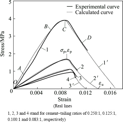
Fig. 1 Compressive stress-strain curves of backfill
2.2 Fracture characteristics of cemented tailings backfill
According to the stress-strain curves above achieved by experiment, four stages of deformation and breakage process under uniaxial compression loading can be defined as follows.
Stage 1: The initial deformation (curve OA section in Fig. 1). The curve slopes upward in this earlier stage, which is attributed to the compression of micro cracks and pores in backfill.
Stage 2: The elastic deformation (curve AB section in Fig. 1). The curve is approximately a straight line. In other words, the elastic modulus varies directly with the cement-tailing ratio and so does the slope of curve.
Stage 3: The yield deformation (curve BC section in Fig. 1). With the increase of stress, the slope of stress-strain curve is gradually reduced to zero, and the higher the cement-tailing ratio is, the more distinct the yielding processes of deformation and the higher the yielding stress will be.
Stage 4: The failure stage (curve CD section in Fig. 1). The slope of curve CD turns negative, which suggests that the bearing capacity of system declines as the deformation rises.
To summarize, from the deformation laws of different backfills, it is evident that before peak stress, the deformation varies inversely with the cement-tailing ratio, which illustrates that the backfill with a higher cement-tailing ratio owns a greater strength; while after peak stress, the lower the cement-tailing ratio is, the smaller the deformation and the more abrupt the occurrence of failure are.
3 Damage of cement-tailing backfill
3.1 Damage constitutive equations of different backfills
Assuming cement-tailing backfill is isotropic, according to the Lemaitre theory of strain equivalent, we have
 (1)
(1)
where σ is the effective stress; E is the elastic modulus; ε is the strain; D is the damage value.
When D=0, the backfill is in no damage state; when D=1, the backfill is in the course of absolute damage or failure.
According to the stress-strain curves above, before peak stress, where ε≤εp (εp is the corresponding peak strain when the stress reaches the highest point at σp in Fig. 1), we can see the crack initiation and propagation at a small scale clearly in backfill. The damage value (D) is expressed as
 (2)
(2)
where A and β are constants.
Combining Eqs. (1) with (2), before peak stress, Eq. (1) can be rewritten as
 (3)
(3)
After peak stress, where εp<ε≤εu (εu is the ultimate strain shown in Curve 2 of Fig. 1), the stress-strain relationship coincides with Mazars model of concrete [13], in which stress drops exponentially with the increase of strain. This means that macro-cracks in backfill and failure came forth. Therefore, in this stage, we can describe the damage value (D) as
 (4)
(4)
where Dp is the damage value when stress reaches its peak value (Dp=Aεp).
Inserting Eq. (4) into Eq. (1), after peak stress, Eq. (1) can be written in the following form:
 (5)
(5)
On the basis of stress-strain curves (Fig. 1) and considering boundary conditions, we can obtain
 (6)
(6)
There are three unknown variables in Eq. (6). By solving Eq. (6), we have
 (7)
(7)
According to experimental data and by solving Eq. (7), we can obtain the values of β, A and B of different backfills (Table 1).
By substituting damage parameters (shown in Table 1) into Eqs. (3) and (5), we can obtain damage constitutive equations of different backfills (Table 2). And by calculating with these equations, we can obtain the stress-strain curves of different backfills (dashed lines of Fig. 1). Compared with experimental curves, the calculated results agree well with experimental data.
3.2 Damage laws of different backfills
It is manifest in Table 1 that damage values (Dp) of different backfills range from 0.156 to 0.207 as the stress reaches its peak, and the damage value increases with the increase of cement-tailing ratio.
Inserting damage parameters (Table 1) into Eqs. (2) and (4), we can obtain damage evolution equations of different backfills; moreover, the relationship between damage value and strain is shown in Fig. 2.
In Fig. 2 we can see that before peak stress the damage values grow gently with the increase of strain. To be more precise, the lower the cement-tailing ratio is, the more slightly the damage value increases. While after peak stress, the damage values go up steeply with the increase of strain, and the damage values get increasingly large with decreasing the ratio.
4 Match between backfill and rock mass
4.1 Mechanical models
The backfill in mining can mechanically support the wall rock, and control the earth-pressure of stope. Owing to the deformation in rock mass during the process of mining, backfills are compressed by the surrounding rock, which releases energy, generates counteractive force and restricts the deformation. And this leads to an interaction system between rock mass and backfill [14,15].
Table 1 Damage parameters of different backfills
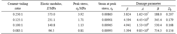
Table 2 Damage constitutive equations of different backfills
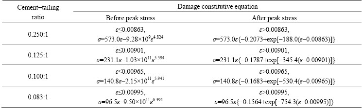
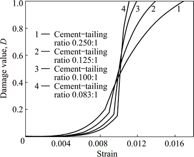
Fig. 2 Relationship between damage value (D) and strain
When we analyzed the mechanical functions of backfill and rock mass, taking the subsequent filling stope for example, backfill was surrounded by surrounding rock and in the three-dimensional stress state after the stope was cement-filled. In order to simplify the mechanical model, lateral restraint and lateral deformation of backfill were neglected, and a (1D) model was used (Fig. 3). As the stiffness and elastic modulus of rock mass were higher than those of backfill (assuming that the elastic modulus of rock is E0), we adopted linear elastic model for rock mass and employed damage constitutive models above proposed for backfill.
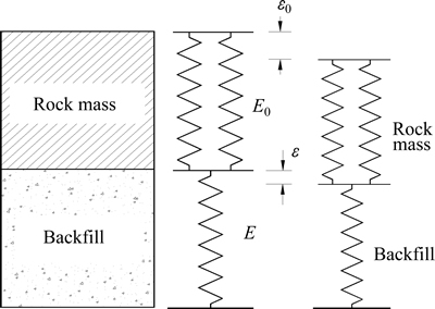
Fig. 3 Mechanical analysis model between rock mass and backfill
4.2 Catastrophe analysis of failure of backfill
From the mechanical analysis of backfill above, we can see that before peak stress the damage value of backfill is relatively low and the breakage of backfill mainly occurs after peak stress. Therefore, it is well-advised to seek the failure laws of backfill by utilizing the model after peak stress. With respect to the mechanical model in Fig. 3, we assume that the deformation in backfill is ε, and total deformation of system is ε0, so the deformation in rock mass is (ε0-ε). The total energy (V) of system is the sum of deformation energy in backfill and in rock mass, and it can be written as
 (8)
(8)
where σ1 is the stress of backfill before peak stress; σ2 is the stress of backfill after peak stress. Substituting Eqs. (3) and (5) into Eq. (8), we can obtain


 (9)
(9)
Through strain derivation to Eq. (9), we can obtain the following equilibrium surface of the system energy:
 (10)
(10)
At the cuspidal points of the equilibrium surface, we have
 (11)
(11)
By solving Eq. (11), we obtain  , which is the cuspidal point.
For the purpose of gaining a standard equation of equilibrium surface, Eq. (10) is expanded to power series at the point  and extracted the front three terms, as a result, we have

 (12)
(12)
 (13)
(13)
For  , there is no
  in Eq. (12). Making
  and inserting it into Eq. (12), we can obtain
 (14)
(14)
 (15)
(15)
 (16)
(16)
According to the catastrophe theory [16-18] and the prerequisite of instable system (p≤0), Eq. (17) can be derived from Eq. (15):
 (17)
(17)
where k is the matching coefficient between backfill and rock mass.
Equation (17) indicates that the system will be unstable according to the energy criterion when k≤1.
4.3 Matching analysis between backfill and rock mass
Equation (17) shows that the stability of energy system is related to elastic modulus of rock mass, elastic modulus of backfill and damage parameters of backfill as well. In order to probe the mechanical laws of Eq. (17), substituting mechanical parameters of backfill with different cement-tailing ratios (Table 1) at the same group of elastic modulus, we calculated the different values of k (Table 3).
Table 3 Calculated results of k with different mechanical parameters (Symbol “+” denotes stable backfill in energy, while symbol “-” denotes instable backfill in energy without matching with rock mass)
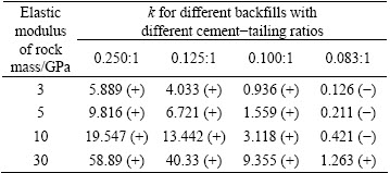
As can be seen from Table 3 that when elastic modulus of rock mass is at the same level, the matching coefficient k between backfill and rock mass decreases with the decrease of the cement-tailing ratio of backfill, and the backfill with a lower cement-tailing ratio is more likely to be unstable; while when the cement-tailing ratio of backfill is at the same level, the matching coefficient k between backfill and rock mass increases with the rising of elastic modulus of rock mass, and the rock mass with a larger elastic modulus has a higher stiffness, which indicates that the stability of the system is stronger. The parameter Ω controls the deformation and breakage in backfill which plays a pivotal role in the stability of the energy system.
The calculated results show that Eq. (17) can be regarded as the guidance to design the strength of backfill in real project. Once the relevant parameters of rock mass and backfill have been given, choosing backfill with a certain cement-tailing ratio and substituting its parameters into k, we can distinguish the stability of the system. When k≤1, the system of backfill and rock mass will become instable and backfill with higher cement-tailing ratio should be chosen until k>1, which indicates that the backfill meets the requirement during the process of mining. Hence, the system instability criterion can be treated as a new way to design the strength of backfill reasonably, and instruct the production of mine.
5 Conclusions
1) There are different mechanical characteristics and damage laws in different backfills. Exactly, the lower the cement-tailing ratio is, the smaller the damage value is before stress stands at its peak. By contrast, the deformation gets increasingly small after peak stress, while the damage grows faster and breakage appears more suddenly.
2) During mining process, rock mass and backfill form a system that holds equilibrium in force and energy. The rock mass with higher elastic modulus and stiffness can ensure that the system is more stable, thus, we can use backfill with lower strength to save mining cost. On the other hand, the elastic modulus of rock mass is probably constant. In this case, the stability declines with the decrease of the cement-tailing ratio.
3) It should be noted that the catastrophe model in this work has examined its feasibility only in one dimension. As the stress state of backfill during mining process is complicated, further researches are expected to create an appropriate catastrophe model suitable for complex mechanical condition in the future.
References
[1] MCHAINA D M, JANUSZEWSKI S, HALLAM R L. Development of an environmental impact and mitigation assessment program for a tailings storage facility stability upgrade [J]. International Journal of Surface Mining, Reclamation and Environment, 2001, 15(2): 123-140.
[2] MEGGYES T, NIEDERLEITHINGER E, WITT K J. Enhancing the safety of tailings management facilities [J]. Soil and Sediment Contamination, 2008, 17(4): 323-345.
[3] FRIEDRICH L, HALDEN N M. Determining exposure history of northern pike and walleye to tailings effluence using trace metal uptake in otoliths [J]. Environmental Science and Technology, 2010, 44(5): 1551-1558.
[4] MOSTAFA B, TIKOU B, BRUNO B. Chemical factors that influence the performance of mine sulphidic paste backfill [J]. Cement and Concrete Research, 2002, 2(7): 1133-1144.
[5] LI Xi-bing, LIU Zhi-xiang. Research on grey prediction of deformation laws in backfill based on phase space reconstruction [J]. Journal of Safety and Environment, 2004, 4(6): 54-57. (in Chinese)
[6] LIU Zhi-xiang, LI Xi-bing, ZHAO Guo-yan. Three-dimensional energy dissipation laws and reasonable matches between backfill and rock mass [J]. Chinese Journal of Rock Mechanics and Engineering, 2010, 29(2): 344-348. (in Chinese)
[7] RYDER J A. Application of numerical stress analyses to the design of deep mine [C]//Proceedings of the International conference on gold. Johannesburg: South African Institute of Mining & Metallurgy Publisher, 1986: 245-253.
[8] GURTUNCA R G, ADAMS D J. Determination of the in situ modulus of the rock mass by the use of backfill measurements [J]. Journal of the South African Institute of Mining and Metallurgy, 1991, 91(3): 81-88.
[9] BLOSS M L, REVELL M. Cannington paste fill system-achieving demand capacity [C]//MassMin 2000. Brisbance: Australasian Institute of Mining and Metallurgy, 2000: 713-719.
[10] BENZAAZOUA M, BELEM T, BUSSIERE B. Chemical factors that influence the performance of mine sulphidic paste backfill [J]. Cement and Concrete Research, 2002, 32(7): 1133-1144.
[11] DEVECI H, ERCIKDI B, KESIMAL A. Cemented paste backfill of sulphide-rich tailings: Importance of binder type and dosage [J]. Cement and Concrete Composites, 2009, 31(4): 268-274.
[12] ERCIKDI B, CIHANGIR F, KESIMAL A. Utilization of water-reducing admixtures in cemented paste backfill of sulphide-rich mill tailings [J]. Journal of Hazardous Materials, 2010, 179(1-3): 940-946.
[13] MAZARS J A. Description of macro scale damage of concreted structures [J]. Engineering Facture Mechanics, 1986, 25(5-6): 729-737.
[14] BONAKDAR A, MOBASHER B. Multi-parameter study of external sulfate attack in blended cement materials [J]. Construction and Building Materials, 2010, 24(1): 61-70.
[15] HU K X, KEMENY J. Fracture mechanics analysis of the effect of backfill on the stability of cut and fill mine workings [J]. International Journal of Rock Mechanics and Mining Sciences, 1994, 31(3): 231-241.
[16] BAUROVA N I. Durability models of adhesive material using catastrophe theory [J]. Polymer Science―Series D, 2009, 2(2): 130-132.
[17] BLAIZOT J P, NOWAK M A. Confinement, turbulence and diffraction catastrophes [J]. Nuclear Physics A, 2009, 827(1-4): 383-385.
[18] ZUO Hong-yan, LUO Zhou-quan, WANG Yi-wei. Prediction of functional link neural network of roof caving based on fuzzy adaptive variable weight method [J]. The Chinese Journal of Nonferrous Metals, 2011, 21(4): 894-900. (in Chinese).
尾砂胶结充填体的损伤破坏及其与岩体的合理匹配
刘志祥,兰 明,肖思友,郭虎强
中南大学 资源与安全工程学院,长沙 410083
摘 要:为了研究充填体的破坏机理及其与岩体的合理匹配,实现金属矿山的安全高效开采,分别对灰砂配比为0.250:1、0.125:0、0.100:1和0.083:1的4种尾砂胶结充填体进行试块单轴抗压实验。通过其应力-应变曲线,分析不同灰砂配比下充填体的变形与破坏特征。在此基础上,采用损伤力学推导建立4种不同配比充填体的损伤本构方程,并通过本构模型与实验结果的对比分析,验证损伤模型的可靠性。此外,利用突变理论,建立充填体与岩体在相互力学作用下的能量模型,推导出充填体与岩体的系统失稳判据。结果表明:不同配比的充填体表现出不同的损伤特性,充填体灰沙配比越低,达到峰值应力时的损伤值越小,且峰值应力后,损伤破坏过程越明显;从系统失稳的条件上看,岩体强度与充填体强度越低,越容易造成系统的失稳。该研究结果为矿山充填体合理强度设计提供了科学依据。
关键词:尾砂胶结充填体;岩体;损伤本构方程;突变理论;匹配;失稳判据
(Edited by Wei-ping CHEN)
Foundation item: Projects (2013BAB02B05, 2012BAB08B01) supported by the National Science and Technology Support Program of China; Project (2013JSJJ029) supported by the Teacher Foundation of Central South University, China; Project (51074177) supported by the Joint Funding of National Natural Science Foundation and Shanghai Baosteel Group Corporation, China
Corresponding author: Zhi-xiang LIU; Tel: +86-13207475458; E-mail: csu_lm@163.com
DOI: 10.1016/S1003-6326(15)63684-6

