
J. Cent. South Univ. (2020) 27: 1530-1542
DOI: https://doi.org/10.1007/s11771-020-4388-9

Influence of steel corrosion to flexural behavior of coral aggregate concrete beam
DA Bo(达波)1, 2, YU Hong-fa(余红发)3, MA Hai-yan(麻海燕)3, WU Zhang-yu(吴彰钰)3
1. Key Laboratory of Coastal Disaster and Defence of Ministry of Education, Hohai University,Nanjing 210098, China;
2. College of Harbour, Coastal and Offshort Engineering, Hohai University, Nanjing 210098, China;
3. Department of Civil Engineering, Nanjing University of Aeronautics and Astronautics,Nanjing 210016, China
 Central South University Press and Springer-Verlag GmbH Germany, part of Springer Nature 2020
Abstract: To study the flexural behavior and calculation model, 8 coral aggregate concrete (CAC) beams with different types of steel were designed. The flexural behavior of CAC beam was tested. The failure mode, bearing capacity, the maximum crack width (ws) and average crack spacing (lm) were studied. A calculation model for the bearing capacity of CAC beam was proposed. The results indicated that with the steel strength increased, the cracking moment (Mcr) and ultimate moment (Mu) of CAC beam increased, and the development of the ws gradually slowed, which effectively inhibited the formation of cracks and improved the flexural behavior of CAC beam. For CAC structures in the ocean engineering, it is recommended to use organic new coated steel to extend its effective service life. In addition, considering the influence of steel corrosion, a calculation model for the Mcr, Mu, lm and ws of CAC beam was established.
Key words: coral aggregate concrete beam; steel corrosion; flexural behavior; bearing capacity; calculation model
Cite this article as: DA Bo, YU Hong-fa, MA Hai-yan, WU Zhang-yu. Influence of steel corrosion to flexural behavior of coral aggregate concrete beam [J]. Journal of Central South University, 2020, 27(5): 1530-1542. DOI: https://doi.org/10.1007/s11771-020-4388-9.
1 Introduction
Far away from the mainland, island-reefs are inconvenient in transportation and are lacking in natural sand and freshwater resources. Besides, tropical island-reefs are rich in coral and seawater resources. Coral is a kind of natural lightweight aggregate and contains CaCO3 of above 96%. Therefore, in order to reduce the cost and follow the construction schedule, coral, coral sand, cement and seawater are used to prepare coral aggregate concrete (CAC) beam to achieve national defense and engineering benefits. In the marine environment, Cl- is main reason leading to steel corrosion, which results in concrete beam failure [1, 2]. In addition, a abundant of Cl- exists in coral and seawater [3-5]. However, the flexural behavior of beam is particularly important to ensure the building structures safety [6, 7]. Therefore, it is necessary to study the flexural behavior of CAC beam.
RICK [8] investigated the CAC building structure in the Bikini Atolls and found that the durability of CAC is mainly affected by salt content, structure crack width and concrete cover thickness. WATTANACHAI et al [9] studied the Cl- diffusion in CAC and found that Cl- diffusion rate in CAC was significantly greater than that of ordinary aggregate concrete (OAC) with the same proportion. KAKOOEI et al [10] studied the steel corrosion in CAC structure by testing its polarization resistance and corrosion current density. ZHANG [11] studied the flexural behavior of CAC beam and found that serious corrosion occurred to the common steel, but none quantitative data analysis was introduced for the cause of corrosion. WANG et al [12] studied the feasibility of steel tube-CAC and the research showed that CAC into steel tube could avoid Cl- corrosion. JIN [13] studied the flexural behavior of CAC beam, and then the mechanical behavior degradation rule of CAC beam was analyzed. DA et al [14, 15] investigated the failure status, steel corrosion and Cl- distribution of CAC structure in the Pacific reef environment and found that the CAC structure suffered from serious corrosion destruction. MA et al [16] studied the flexural behavior of CAC beam and OAC beam and the research showed that the failure characteristics of CAC beam and OAC beam are similar. At present, the studies on CAC mostly concentrated on its material performance and durability.
Therefore, this paper, by testing the flexural behavior of CAC beam, aims to study what affects crack, failure mode, plane section assumption, bearing capacity, the maximum crack width (ws) and average crack spacing (lm). Considering the influence of steel corrosion, a calculation model for the cracking moment (Mcr), ultimate moment (Mu), lm and ws of CAC beam was proposed.
2 Experiment
2.1 Raw materials
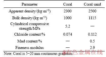
The basic physical property parameters of coral aggregate are shown in Table 1 [17]. The binder materials and admixtures selected were P・II52.5 ordinary Portland cement, slag (SG), fly ash (FA), calcium nitrate inhibitor and polycarboxylate water-reducer. The mass proportion of seawater per unit volume is NaCl to Na2SO4 to MgCl2 to 6H2O to KCl to CaCl2=24.5: 4.1:11.1:0.7:1.2. The steels selected were common steel (A), organic new coated steel (B), zinc- chromium coated steel (C), 2205 duplex stainless steel (D) and 316 stainless steel (E).
Table 1 Physical property parameters of coral and coral sand
2.2 Component preparation
The sizes of the CAC beam were 150 mm×200 mm×1500 mm (Figure 1). The proportion of CAC per unit volume was coral to coral sand to cement to SG to FA to water to water-reducer to inhibitor=300:700:780:150:70:264:6:30 (kg/m3). The concrete strength was C60 and the apparent density was 2267 kg/m3. The basic parameters of CAC beam are shown in Table 2. In addition, the longitudinal steel was 2Φ16 twisted steel, the hanger steel was 2 Φ10 twisted steel and the stirrup was Φ6 plain steel (double legs).
The coral aggregates natural porous structure, so the part of seawater was pre-absorbed into coral and coral sand. Then the cement, coral aggregate, FA and SG were put into the mixer and mixed for one minute. Next, the mixture of water-reducer, seawater and inhibitor was added to the mixer, mixing for 3 min. The mixture was poured to shape into CAC beam. After molding, the beam was poured into seawater to cure for 90 d.
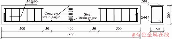
Figure 1 Schematic diagram of CAC beam (Unit: mm)
Table 2 Basic parameters of CAC beam
2.3 Test method
According to GB/T 50152-2012, the test adopted the 4-point loading method. The loading devices are shown in Figure 2. A load sensor was used to measure the load changes during loading. The data of steel strain gauge, concrete strain gauge and displacement sensor were collected by static strain meter. Besides, the crack width was measured by crack observer (measuring accuracy was 0.02 mm). In order to measure the steel stress, the 6 strain gauges were attached to the midspan of longitudinal steels and the loading points. To measure the deformation of beam, the 5 strain gauges were attached to the pure bending section of beam. A strain gauge was pasted in the tensile and compression zone respectively to explore the concrete strain development (Figure 1).
3 Test results and analyses
3.1 Failure mode
Figure 3 shows that the cracks on each CAC beam basically followed the rules as follows: 1) The cracks often occurred in the midspan and the loading points; 2) 30%-70% of the beam height was ran through by the first crack. The crack extended upward along the beam with the load increased, whereas crack length grew slowly in the later period. At the same time, the increase of crack width was initially slow but rapid after the steel yielded until the crack width reached 1.5 mm; 3) The bearing capacity dropped by 2-5 kN when the new cracks appeared.
3.2 Plane section assumption
Figure 4 shows that the plane section assumption was well satisfied with CAC beam of a small external load. When the load increased and the cracks gradually widened, the concrete in the CAC beam tension zone began to fail, and the beam could no longer meet the plane section assumption. Although the concrete could not withstand the load acting on the beams, the section strain in the rest parts might still conform to the plane section assumption.
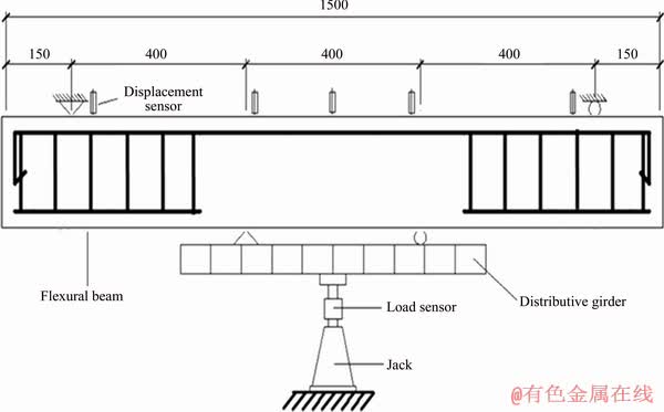
Figure 2 Schematic of loading devices (Unit: mm)
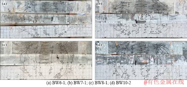
Figure 3 Failure mode of CAC beam:
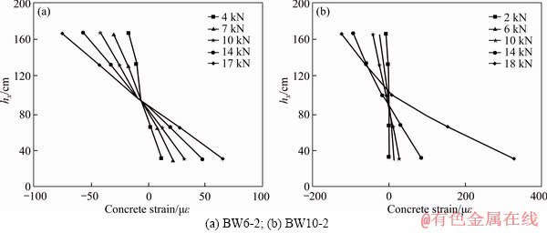
Figure 4 Midspan strain curves of CAC beam:
3.3 Load-deflection
3.3.1 Moment-midspan deflection
Figure 5 shows that for the different types of steel, the rules of the midspan deflection of CAC beam are as follows: common steel>zinc-chromium coated steel>organic new coated steel>316 stainless steel. The rule of Mu was opposite. This main reason is that the yield strength of common steel was significantly smaller than that of 316 stainless steel and the stainless steel had good flexural strength, so, its midspan deflection was the smallest while its Mu was the strongest. Besides, the 2205 duplex stainless steel is plain steel, resulting in a greater slip between steel and CAC; therefore, the midspan deflection of 2205 duplex stainless steel was the largest.
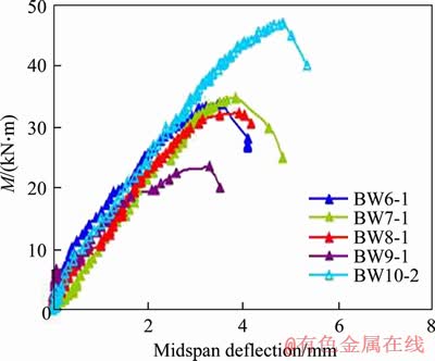
Figure 5 Moment-midspan deflection curves of CAC beam
3.3.2 Deflection-beam length
Figure 6 shows that the overall deflection of CAC beam is symmetrical. Before the load reached the ultimate load, the increase in the amplitude of deflection remained roughly constant. Furthermore, the overall deflection increased abruptly when the load approached to the ultimate load.
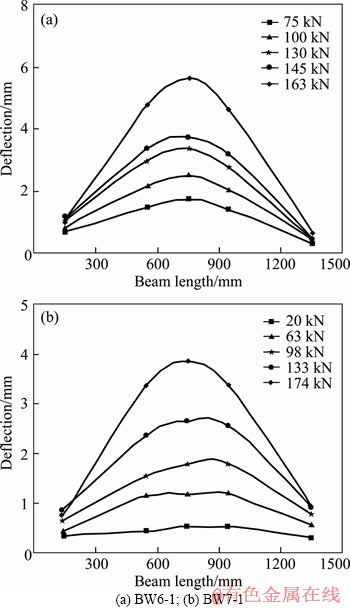
Figure 6 Deflection-beam length curves of CAC beam:
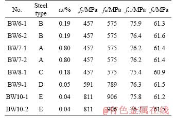
3.4 Bearing capacity
Table 3 shows that the rules of the Mcr and Mu of CAC beam are as follows: the 2205 duplex stainless steel is the smallest, the common steel, zinc-chromium coated steel and organic new coated steel are second and the 316 stainless steel is the greatest. It shows that with the steel strength increased, the Mcr and Mu of CAC beam increased. The main reasons are that: 1) Before cracking, the tensile steel shared parts of the tensile stress. When the steel strength increased, the tensile performance of steel improved, and Mcr increased. 2) The CAC beam bearing capacity comprised the flexural capacity of steel and the splitting tensile capacity of concrete. As the steel strength increased, the flexural capacity increased, and thus the Mu of CAC beam increased.
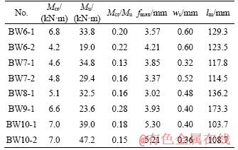
Table 3 Test results of CAC beam
Mu of zinc-chromium coated steel (BW8-1) or organic new coated steel (BW6-1) is slightly greater than that of common steel (BW7-2). The main reason is abundant Cl- in the CAC, which leads to severe corrosion of common steel, and narrows the effective section of the steel [18, 19], thus reducing the Mu of BW7-2.
3.5 Maximum crack width
Figure 7 shows relative moment-maximum crack width (ws) curves of CAC beam. With the load increased, the ws increased. In the initial stage of loading, the ws increased slowly; when approaching the ultimate load, the ws increased rapidly, leading to CAC beam failure. For the same ws, the bearing capacity of BW10-2 was the largest.
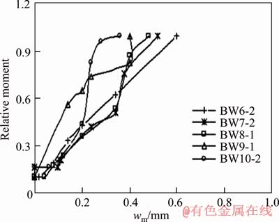
Figure 7 Relative moment-maximum crack width curves of CAC beam
In addition, for the CAC beam with the same ws (0.3 mm), M of BW6-2, BW7-2, BW8-1, BW9-1 and BW10-2 reached 57.7%, 50.1%, 52.3%, 83.3% and 88.5% of Mu, respectively. It showed that the development of ws was related to the steel strength. The 316 stainless steel strength was significantly greater than that of common steel, which effectively inhibited the formation of cracks and improved the flexural behavior of CAC beam.
3.6 Crack space
Figure 8 shows average crack space (lm) of CAC beam. The rule of the lm of CAC beam with different steel types is as follows: 316 stainless steelm increased.
3.7 Calculation model
3.7.1 Steel corrosion
Figure 9 shows corrosion status of different steel types of CAC beam after a 90 d test. The common steel had “pit erosion” in different degrees and the organic new coated steel mainly showed slight corrosion, indicating that the coated steel has better anti-corrosion. Figure 10 shows electrochemistry test results of different steel types in CAC. The concrete strength is C60, the steel diameter is 10 mm and the concrete covered thickness is 15 mm. The results of Figure 9 and Figure 10 are consistent. In addition, the maximum section loss rate (ωsm) and mean section loss rate (ωs) of the BW6-1 are tested by 3D laser rapid scanning technology (Figure 11). ZHANG et al [20] found that steel corrosion mainly causes the reduction of steel section and strength, and thus the bearing capacity of reinforced concrete beam decreases. YUAN et al [21] proposed comprehensive reduction coefficient (α) considering the reduction of steel strength and section caused by steel corrosion and the calculation formula is as follows:
 (1)
(1)
where the parameters are shown in nomenclature.
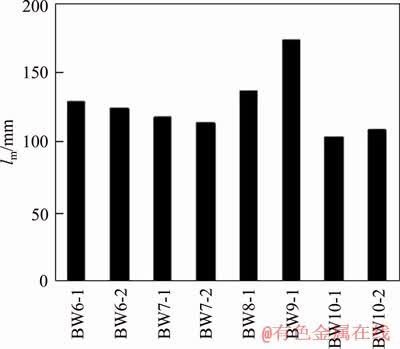
Figure 8 Average crack space of CAC beam
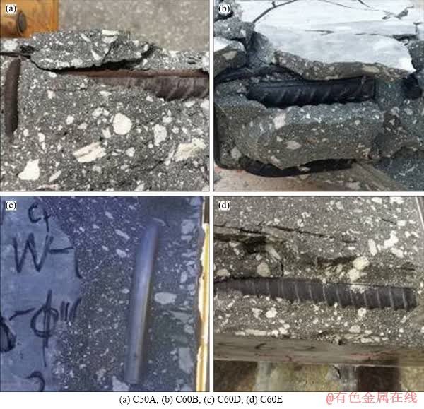
Figure 9 Corrosion status of different steel types of CAC beam:
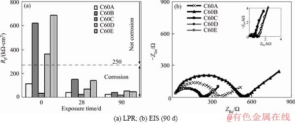
Figure 10 Electrochemistry test results of different steel types in CAC:
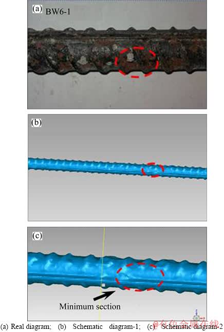
Figure 11 3D laser rapid scanning technology:
MA et al [16] and DA et al [22] studied ωsm and ωs of CAC beam and showed that the relationship between ωsm and ωs is as follows:
ωsm=1.301ωs (2)
where ωsm is the maximum section loss rate (%); the other parameters are consistent with Eq. (1).
For the steel, the ωsm of steel is the most likely to fracture. Therefore, it is more reasonable to use ωsm to calculate α. In addition, ZHANG et al [20] and YUAN et al [21] showed that mass loss rate (ω) is equal to ωs. So, α is expressed as:
 (3)
(3)
where the parameters are consistent with Eq. (1).
3.7.2 Cracking moment
The suggested calculation formula for the Mcr of OAC beam in GB 50010-2010 is as follows:
 (4)
(4)
where γ is influence coefficient of sectional resistance moment; γm=1.55, h=400 mm; other parameters are shown in nomenclature.
The suggested calculation formula for the Mcr of lightweight aggregate concrete (LAC) beam and CAC beam in JGJ 12-2006 and result of ZHANG [11] is as follows:
 (5)
(5)
where for the LAC beam, γsh=0.8, γ=1.75; for the CAC beam, γ=1.75, plain steel γm=0.9, twisted steel γm=1.0; other parameters are shown in nomenclature.
Mcrc and Mcrt are shown in Figure 12 and Table 4, showing a large error between Mcrc and Mcr. Therefore, considering the influence of steel corrosion on steel section decrease, the calculation formula for the Mcr of CAC beam is as follows:
 (6)
(6)
or
 (7)
(7)
where the parameters are consistent with Eq. (1), Eq. (4) and Eq. (5).
3.7.3 Ultimate moment
The suggested calculation formula for the Mu of OAC beam in GB 50010-2010 is as follows:
 (8)
(8)
The suggested calculation formula for the Mu of LAC beam and CAC beam in JGJ 12-2006 and ZHANG [11] is as follows:
 (9)
(9)
where fcm is concrete flexural compressive strength (MPa); for the LAC, fcm=1.1fc; for the CAC, fcm=1.05fc; other parameters are shown in nomenclature.
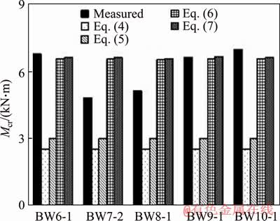
Figure 12 Comparison of Mcrc (calculated value) and Mcrt (measured value) of CAC beam
Muc (calculated value) and Mut (measured value) are shown in Table 5 and Figure 13. It is shown that the error between Muc and Mut is small. However, fcm is no longer used in the current standards. Thus, considering the influence of steel corrosion on the reduction of steel section and strength, the calculation formula for the Mu of CAC beam is as follows:
 (10)
(10)
where the parameters are consistent with Eq. (1), Eqs. (8) and (9).
Table 4 Mcrcand Mcrt of CAC beam (Mcrc: calculated value; Mcrt: measured value)
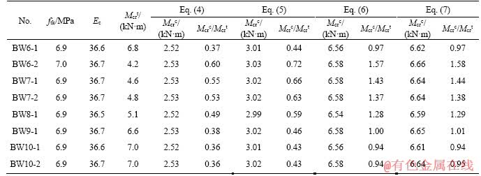
Table 5 Mucand Mut of CAC beam
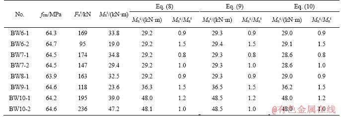
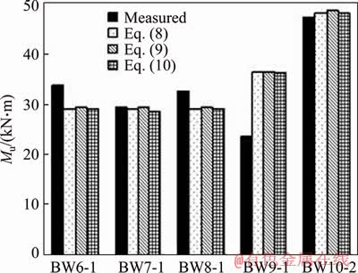
Figure 13 Comparison of Muc and Mutof CAC beam
3.7.4 Average crack space
According to the GB 50010-2010, JGJ 12-2006 and result of ZHANG [11], the calculation formula for lm is as follows:
OAC beam:
 (11)
(11)
LAC beam:
 (12)
(12)
CAC beam:
 (13)
(13)
where the parameters are shown in nomenclature.
lmc (calculated value) and lmt (measured value) are shown in Figure 14 and Table 6. It is shown that the errors between lmc and lmt fitted by Eqs. (11)- (13) were 6%, 25% and 24%, respectively. Based on the reasonability, Eq. (11) was selected as the calculation formula.
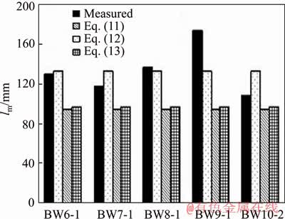
Figure 14 Comparison of lmc and lmtof CAC beam
3.7.5 Maximum crack width
According to the GB 50010-2010, JGJ 12-2006, and result of ZHANG [11], the calculation formula for ws is as follows:
OAC beam and LAC beam:
 (14)
(14)
CAC beam:
 (15)
(15)
where αc is crack width influence coefficient, αc=0.85; ψ is non-uniform coefficient of steel; When ψ>1.0, ψ=1.0; when ψ<0.2, ψ=0.2; other parameters are shown in nomenclature.
wsc and wst are shown in Table 7 and Figure 15,showing a large error between wsc and wst. Therefore, considering the influence of steel corrosion on the steel section decrease, the calculation formula for the ws of CAC beam is as follows:
ws=2.1ψσsklm/Es (16)
where the parameters are consistent with Eq. (1),Eqs. (14) and (15).
Table 6 lmc and lmt of CAC beam
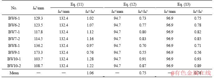
Table 7 wsc and wst of CAC beam
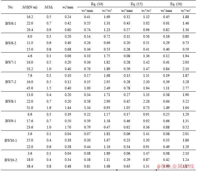
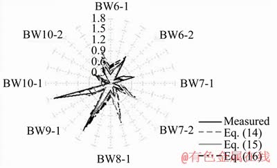
Figure 15 Comparison of wsc and wstof CAC beam
4 Conclusions
1) For different types of steel, the rule of the midspan deflection of CAC beam is as follows: common steel>zinc-chromium coated steel>organic new coated steel>316 stainless steel. Furthermore, the rule of the Mu was opposite.
2) At all stages, the overall deflection of CAC beam was always symmetrical. Before the load reached the ultimate load, the increase in amplitude of deflection remained roughly constant. Furthermore, the overall deflection increased abruptly when the load approached to the ultimate load.
3) With the load increased, the ws increased. At the initial stage of loading, the ws increased slowly; when approaching the ultimate load, the ws increased rapidly, leading to beam failure. With the steel strength increased, the development of the ws gradually slowed, which effectively inhibited the formation of cracks and improved the flexural behavior of CAC beam.
4) For CAC structures, it is recommended to adopt organic new coated steel to extend its effective service life. In addition, considering the influence of steel corrosion, a calculation model for the Mcr, Mu, lm and ws of CAC beam was established.
Nomenclature
CAC
Coral aggregate concrete
OAC
Ordinary aggregate concrete
LAC
Lightweight aggregate concrete
SG
Slag
FA
Fly ash
LPR
Linear polarization resistance
EIS
Electrochemical impedance spectroscopy
Rp
Polarization resistance
fy
Yield strength of steel
fu
Ultimate strength of steel
fcu
Cube compressive strength of concrete
fc
Axial tensile strength of concrete
ftk
Tensile strength of concrete
fcm
Flexural compressive strength of concrete
ws
Maximum crack width
lm
Average crack spacing
Mcr
Cracking moment
Mu
Ultimate moment
W0
Elastic resistance moment
hx
Section height of beam
ρ
Steel ratio
ωsm
Maximum section loss rate
ωs
Mean section loss rate
ω
Mass loss rate
α, α2, α3
Reduction coefficient
I0
Inertia moment
γ
Influence coefficient
b
Section width
y0
Height of compression zone
h0
Section effective height
n
Ratio of elastic modulus
As
Steel sectional area in the tension zone
x
Height in the compression zone
αc
Crack width influence coefficient
cs
Concrete cover thickness
ψ
Non-uniform coefficient of steel
dep
Steel equivalent diameter
σs
Stress of steel
Ate
Section area of concrete
Es
Elastic modulus of steel
References
[1] TANG Lu-ping. Engineering expression of the ClinConc model for prediction of free and total chloride ingress in submerged marine concrete [J]. Cement and Concrete Research, 2008, 38: 1092-1097. DOI: 10.1016/j.cemconres. 2008.03.008.
[2] LU Chun-hua, CUI Zhao-wei, LIU Rong-gui, LIU Qi-dong. Chloride diffusivity in flexural cracked Portland cement concrete and fly ash concrete beams [J]. Journal of Central South University, 2014, 21(9): 3682-3691. DOI: 10.1007/ s11771-014-2351-3.
[3] DA Bo, YU Hong-fa, MA Hai-yan, TAN Yong-shan, MI Ren-jie, DOU Xue-mei. Chloride diffusion study of coral concrete in a marine environment [J]. Construction and Building Materials, 2016, 123: 47-58. DOI: 10.1016/ j.conbuildmat.2016.06.135.
[4] DA Bo, YU Hong-fa, MA Hai-yan, WU Zhang-yu. Reinforcement corrosion research based on electrochemical impedance spectroscopy for coral aggregate seawater concrete in a seawater immersion environment [J]. Journal of Testing and Evaluation, 2020, 48: 1537-1553. DOI: 10.1520/JTE20180197.
[5] DA Bo, YU Hong-fa, MA Hai-yan, WU Zhang-yu. Research on compression behavior of coral aggregate reinforced concrete columns under large eccentric compression loading [J]. Ocean Engineering, 2018, 155: 251-260. DOI: 10.1016/ j.oceaneng.2018.02.037.
[6] AL-OSTA M A, ISA M N, BALUCH M H, RAHMAN M K. Flexural behavior of reinforced concrete beams strengthened with ultra-high performance fiber reinforced concrete [J]. Construction and Building Materials, 2017, 134: 279-296. DOI: 10.1016/j.conbuildmat.2016.12.094.
[7] YU Yu-lin, YIN Shi-ping, NA Ming-wang. Bending performance of TRC-strengthened RC beams with secondary load under chloride erosion [J]. Journal of Central South University, 2019, 26(1): 196-206. DOI: 10.1007/s11771- 019-3993-y.
[8] RICK A E. Coral concrete at bikini atoll [J]. Concrete International, 1991, 13(1): 19-24. https://www.concrete.org/ publications/internationalconcreteabstractsportal/m/details/id/3605.
[9] WATTANACHAI P, OTSUKI N, SAITO T, NISHIDA T. A study on chloride ion diffusivity of porous aggregate concretes and improvement method [J]. Doboku Gakkai Ronbunshuu E, 2009, 65(1): 30-44. DOI: 10.2208/jsceje. 65.30.
[10] KAKOOEI S, AKIL H M, DOLATI A, ROUHI J. The corrosion investigation of rebar embedded in the fibers reinforced concrete [J]. Construction and Building Materials, 2012, 35: 564-570. DOI: 10.1016/j.conbuildmat.2012. 04.051.
[11] ZHANG Wen. Experimental study on reinforced coral aggregate concrete component [D]. Nanjing: Hohai University, 1995. (in Chinese)
[12] WANG Fang, ZHA Xiao-xiong. Experimental and theoretical study on coral concrete filled steel tube [J]. Journal of Building Structures, 2013, 34(S1): 288-293. https://www. researchgate.net/publication/296185875.
[13] JIN Yun-dong. Research on short- and long-term mechanical properties of BFRP bar reinforced marines and concrete beams [D]. Nanjing: Southeast University, 2016. (in Chinese)
[14] DA Bo, YU Hong-fa, MA Hai-yan, ZHANG Ya-dong, ZHU Hai-wei, YU Qiang, YE Hai-min, JING Xian-shuang. Factors influencing durability of coral concrete structure in South China Sea [J]. Journal of the Chinese Ceramic Society, 2016, 44(2): 254-261. DOI: 10.14062/j.issn.0454-5648.2016. 02.11. (in Chinese)
[15] YU Hong-fa, DA Bo, MA Hai-yan, ZHU Hai-wei, YU Qiang, YE Hai-min, JING Xian-shuang. Durability of concrete structures in tropical atoll environment [J]. Ocean Engineering, 2017, 135: 1-7. DOI: 10.1016/j.oceaneng. 2017.02.020.
[16] MA Hai-yan, DA Bo, YU Hong-fa, WU Zhang-yu. Research on flexural behavior of coral aggregate reinforced concrete beams [J]. China Ocean Engineering, 2018, 32(5): 593-604. DOI: 10.1007/s13344-018-0061-6.
[17] DA Bo, YU Hong-fa, MA Hai-yan, TAN Yong-shan, MI Ren-jie, DOU Xue-mei. Experimental investigation of whole stress-strain curves of coral concrete [J]. Construction and Building Materials, 2016, 122: 81-89. DOI: 10.1016/ j.conbuildmat.2016.06.064.
[18] YI Wei-jian, KUNNATH S K, SUN Xiao-dong, SHI Cai-jun, TANG Fu-jian. Fatigue behavior of reinforced concrete beams with corroded steel reinforcement [J]. ACI Structural Journal, 2010, 107: 526-533. https://www.concrete.org/ publications/internationalconcreteabstractsportal/m/details/id/51663903.
[19] OU Yu-chen, CHEN Hou-heng. Cyclic behavior of reinforced concrete beams with corroded transverse steel reinforcement [J]. Journal of Structural Engineering, 2014, 140(9): 1629-1635. DOI: 10.1061/(ASCE)ST.1943-541X. 0000932.
[20] ZHANG Wei-ping, ZHOU Bin-bin, GU Xiang-lin, DAI Hong-chao. Probability distribution model for cross-sectional area of corroded reinforcing steel bars [J]. Journal of Materials in Civil Engineering, 2014, 26: 822-832. DOI: 10.1061/(ASCE)MT.1943-5533.0000888.
[21] YUAN Ying-shu, JIA Fu-ping, CAI Yue. The structural behavior deterioration model for corroded reinforced concrete beams [J]. China Civil Engineering Journal, 2001, 34(3): 47-52, 96. DOI: 10.3321/j.issn:1000-131X.2001. 03.009.
[22] DA Bo, YU Hong-fa, MA Hai-yan, ZHU Hai-wei, WU Zhang-yu, MEI Qi-quan. Influence of concrete strength grade to the shear behavior of coral aggregate reinforced concrete beam [J]. Scientia Sinica Technologica, 2019, 49(2): 212-222. DOI: 10.1360/N092018-00267.
(Edited by YANG Hua)
中文导读
钢筋锈蚀对珊瑚混凝土梁抗弯性能的影响
摘要:本文研究了钢筋锈蚀对珊瑚混凝土(CAC)梁抗弯性能的影响。首先,对8根不同种类钢筋的CAC梁进行抗弯性能试验,研究其破坏机理及承载能力。结果显示:CAC梁的抗弯性能随着钢筋强度的提高而增强。此外,由于珊瑚骨料和海水中含有大量Cl-,使得CAC梁中的普通钢筋极易发生锈蚀。因此,对于岛礁工程,采用有机新涂层钢筋能延长CAC结构的有效服役寿命。最后,考虑钢筋锈蚀的影响,建立了CAC梁的开裂弯矩(Mcr)、极限弯矩(Mu)、平均裂缝间距(lm)和最大裂缝宽度(ws)的计算模型。
关键词:珊瑚混凝土梁;钢筋锈蚀;抗弯性能;承载能力;计算模型
Foundation item: Projects(11832013, 51878350) supported by the National Natural Science Foundation of China; Project(B200201063) supported by the Fundamental Research Funds for the Central Universities, China; Project(BK20180433) supported by the Natural Science Foundation of Jiangsu Province, China
Received date: 2018-07-01; Accepted date: 2020-03-13
Corresponding author: YU Hong-fa, PhD, Professor; Tel: +86-25-84895233; E-mail: yuhongfa@nuaa.edu.cn; ORCID: 0000-0002-9293- 9482; MA Hai-yan, PhD, Lecturer; Tel: +86-25-84895233; E-mail: mahaiyan@nuaa.edu.cn; ORCID: 0000-0002- 9282-5944

