TiZrNiCu非晶钎料钎焊TiBw/TC4复合材料和Ti60合金
来源期刊:中国有色金属学报(英文版)2017年第10期
论文作者:宋晓国 张特 冯养巨 檀财旺 曹健 张文丛
文章页码:2193 - 2201
关键词:钎焊;TiBw/TC4复合材料;Ti60合金;界面结构;断裂
Key words:brazing; TiBw/TC4 composite; Ti60 alloy; interfacial microstructure; fracture
摘 要:使用TiZrNiCu 非晶钎料成功实现了TiBw/TC4 复合材料和 Ti60 合金的钎焊连接。通过扫描电子显微镜、能谱仪、X 射线衍射仪及万能材料试验机表征钎焊接头的组织及性能。在940 °C保温10 min下,钎焊接头的典型界面组织为TiBw/TC4 复合材料/ β-Ti+TiB晶须/(Ti,Zr)2(Ni,Cu)金属间化合物层/β-Ti 层/Ti60 合金。钎焊过程中元素向母材中的扩散过程直接影响接头界面结构。钎焊温度的升高使(Ti,Zr)2(Ni,Cu) 金属间化合物层的厚度减小,当钎焊温度超过1020 °C时,(Ti,Zr)2(Ni,Cu)金属间化合物层消失。钎焊温度较低时,生成的脆性相 (Ti,Zr)2(Ni,Cu)不利于接头性能。接头剪切强度随钎焊温度的升高呈先增加后降低的趋势,在1020 °C下获得最大的剪切强度368.6 MPa;而当钎焊温度达到1060 °C时,接头强度降低,这是由于形成了粗大的层状(α+β)-Ti组织。
Abstract: TiBw/TC4 composite was brazed to Ti60 alloy successfully using TiZrNiCu amorphous filler alloy, and the interfacial microstructures and mechanical properties were characterized by SEM, EDX, XRD and universal tensile testing machine. The typical interfacial microstructure was TiBw/TC4 composite/ β-Ti + TiB whiskers/ (Ti,Zr)2(Ni,Cu) intermetallic layer/ β-Ti/ Ti60 alloy when being brazed at 940 °C for 10 min. The interfacial microstructure evolution was influenced strongly by the diffusion and reaction between molten fillers and the substrates. Increasing brazing temperature decreased the thickness of brittle (Ti,Zr)2(Ni,Cu) intermetallic layer, which disappeared finally when the brazing temperature exceeded 1020 °C. Fracture analyses indicated that cracks were initialized in the brittle intermetallic layer when (Ti,Zr)2(Ni,Cu) phase existed in the brazing seam. The maximum average shear strength of joints reached 368.6 MPa when brazing was conducted at 1020 °C. Further increasing brazing temperature to 1060 °C, the shear strength was decreased due to the formation of coarse lamellar (α+β)-Ti structure.
Trans. Nonferrous Met. Soc. China 27(2017) 2193-2201
Xiao-guo SONG1,2, Te ZHANG2, Yang-ju FENG2, Cai-wang TAN1,2, Jian CAO1, Wen-cong ZHANG2
1. State Key Laboratory of Advanced Welding and Joining, Harbin Institute of Technology, Harbin 150001, China;
2. Shandong Provincial Key Laboratory of Special Welding Technology, Harbin Institute of Technology at Weihai, Weihai 264209, China
Received 24 June 2016; accepted 21 March 2017
Abstract: TiBw/TC4 composite was brazed to Ti60 alloy successfully using TiZrNiCu amorphous filler alloy, and the interfacial microstructures and mechanical properties were characterized by SEM, EDX, XRD and universal tensile testing machine. The typical interfacial microstructure was TiBw/TC4 composite/ β-Ti + TiB whiskers/ (Ti,Zr)2(Ni,Cu) intermetallic layer/ β-Ti/ Ti60 alloy when being brazed at 940 °C for 10 min. The interfacial microstructure evolution was influenced strongly by the diffusion and reaction between molten fillers and the substrates. Increasing brazing temperature decreased the thickness of brittle (Ti,Zr)2(Ni,Cu) intermetallic layer, which disappeared finally when the brazing temperature exceeded 1020 °C. Fracture analyses indicated that cracks were initialized in the brittle intermetallic layer when (Ti,Zr)2(Ni,Cu) phase existed in the brazing seam. The maximum average shear strength of joints reached 368.6 MPa when brazing was conducted at 1020 °C. Further increasing brazing temperature to 1060 °C, the shear strength was decreased due to the formation of coarse lamellar (α+β)-Ti structure.
Key words: brazing; TiBw/TC4 composite; Ti60 alloy; interfacial microstructure; fracture
1 Introduction
Titanium alloys are important engineering materials with a diverse range of applications because they possess highly desirable performance characteristics such as low density, good specific strength and excellent corrosion resistance, such as Ti-6Al-4V (TC4) alloy and Ti60 alloy [1-6]. However, their full potential structural applications are limited to a large extent due to the inferior wear resistance and considerable loss in mechanical strength at elevated temperatures. In order to overcome these drawbacks and further enhance the mechanical properties of titanium substrates at elevated temperatures, much attention has been paid to titanium matrix composites (TMCs), which can offer a combination of good mechanical properties and high temperature durability. In particular, HUANG et al [7] compared superplastic tensile behavior of TiBw/TC4 composites to that of TC4 alloy, drawing a conclusion that the higher elongation of TiBw/TC4 composites can be contributed to TiBw reinforcement.
Material joining is an important way to expand the application of the TMCs and titanium alloys. In the joining method of alloys, brazing is an effective method owing to its convenience and cost-effectiveness. In recent years, more researches have focused on brazing titanium alloys and TiAl alloys, and the brazing filler metal is of importance in determination of interfacial microstructures and joining properties of the joints. For example, CHANG et al [8] brazed aluminum alloy and TC4 successfully using Al-Si-Cu-Ge filler metals; SONG et al [9] brazed Ti53311S alloy using Cu foil by contact reactive brazing method; YANG et al [10,11] joined TiAl alloy with Ti37.5-Zr37.5-Ni15-Cu10 brazing powders successfully by vacuum brazing method. Among the brazing fillers, Ti-based filler metals were usually selected to braze titanium alloys to other materials due to their good wettability and compatibility on the substrates, such as the TiZrNiCu amorphous filler alloy [12,13], TiCuNi filler alloys [14] and TiNiV filler alloy [15], and reliable joints were obtained. However, all the researches were concentrated on the joining of titanium alloys or TiAl-based alloys, but study on the joining of TMCs is rarely reported.
In this work, the joining process of TC4 composite reinforced by in situ TiB whiskers (TiBw/TC4 composite) was studied, and the TiZrNiCu amorphous filler alloy was applied as the brazing filler to join TiBw/TC4 composite to Ti60 alloy. The interfacial microstructure and mechanical properties of TiBw/TC4-Ti60 brazed joints were studied by scanning electron microscopy and shear test, respectively. In particular, the influence of brazing temperature on the interfacial microstructure and joining properties of brazed joints were investigated.
2 Experimental
TiBw/TC4 composite used in this study is a newly developed titanium composite fabricated by synthesizing in situ TiB whisker (TiBw) reinforcement in TC4 base material. Figures 1(a) and (b) show the microstructure and XRD pattern of TiBw/TC4 composite, respectively. It is seen clearly that the TiBw/TC4 composite mainly consists of a typical (α+β) Ti alloy matrix microstructure, presenting plate-like and equiaxed α-Ti phase, intergranular β-Ti phase and homogeneous network-like distribution of TiB whiskers. HUANG et al [16] and LU et al [17] reported that the TiB phase tended to display whisker morphology due to its special B27 crystal structure. Furthermore, HUANG et al [18] indicated that the formation of network microstructure was mainly attributed to the usage of large spherical TC4 particles, the low energy milling process and subsequent solid state sintering process. Ti60 alloy used in this study, which belongs to near-α high-temperature titanium alloy, was provided by Northwest Institute for Non-ferrous Metal Research, Xi’an, China. The microstructure and XRD pattern of Ti60 alloy are given in Figs. 1(c) and (d), respectively. It is seen that the original microstructure of Ti60 alloy consists of primary α-Ti phase platelets (gray region) separated by discontinuous retained β-Ti phases (bright region), which located at the grain boundaries.
Amorphous TiZrNiCu, in the form of foil, with 20 μm in thickness, was selected to join TiBw/TC4 composite to Ti60 alloy due to its good compatibility with the two titanium substrates. The solidus temperature (Ts) and liquidus temperature (Tl) were about 820 and 850 °C respectively, which were tested by differential thermal analysis. The main chemical compositions of TiBw/TC4 composite, Ti60 alloy and amorphous TiZrNiCu filler alloy are listed in Table 1, and the corresponding XRD pattern (Fig. 2) indicates the amorphous structure of the filler.
Prior to brazing, TiBw/TC4 composite and Ti60 alloy were cut with the dimensions of 5 mm × 5 mm × 5 mm and 10 mm × 20 mm × 3 mm to produce substrates for joining, respectively. The brazing surfaces of both TiBw/TC4 composite and Ti60 alloy samples were ground on SiC grit papers and then polished using diamond pastes. All of the polished samples were cleaned in acetone by ultrasonic bath for up to 10 min. Subsequently, the amorphous TiZrNiCu foil (5.5 mm × 5.5 mm × 20 μm) was sandwiched between TiBw/TC4 composite block and Ti60 alloy block, as shown in Fig. 3(a).

Fig. 1 Microstructures (a, c) and XRD patterns (b, d) of TiBw/TC4 composite and Ti60 alloy
Table 1 Chemical compositions of substrates and amorphous TiZrNiCu filler alloy (mass fraction, %)


Fig. 2 XRD pattern of TiZrNiCu filler alloy
The brazing procedures were performed in a vacuum furnace, in which a vacuum of (1.3-2.0)×10-3 Pa was kept. Five brazing temperatures, 900, 940, 980, 1020 and 1060 °C, were chosen to perform the brazing experiments. At the beginning of brazing process, the furnace was heated to 750 °C at a rate of 20 °C /min, and then the temperature continued to increase to the brazing temperature at a rate of 10 °C/min. At brazing temperature, the furnace dwelled for 10 min. The cooling rate was 10 °C/min between brazing temperature and 600 °C, followed by the furnace cool to room temperature. During the entire brazing process, a pressure of 20 kPa was applied to the brazing samples to ensure a good contact.
The interfacial microstructures of TiBw/TC4-Ti60 brazed joints were observed using scanning electron microscope (SEM, Quanta 200FEG). Chemical composition analyses of reaction phases in brazed joints were performed using an energy dispersive spectrometer (EDS) with the operation voltage of 20 kV and minimum spot size of 1 μm. In order to further identify the interfacial reaction phases, the fracture surfaces were characterized using X-ray diffraction spectrometer equipped with Cu Kα radiation (XRD, JDX-3530M). The shear tests of brazed joints were conducted at a constant speed of 0.5 mm/min by a universal testing machine (Instron 1186) at room temperature. The schematic diagram of shear test is illustrated in Fig. 3(b). For each set of experimental data, at least five samples were used to average the shear strength of joints. After shear test, the fracture surfaces of brazed joints were examined by SEM to clarify the fracture mode and fracture locations.
3 Results and discussion
3.1 Interfacial microstructure of TiBw/TC4-Ti60 brazed joints
As shown in Fig. 4(a), reliable brazed joint of TiBw/TC4 composite and Ti60 alloy was achieved using amorphous TiZrNiCu as filler alloy at 940 °C for 10 min. The brazed joint can be divided into three reaction zones by the difference in microscopic morphology: Zone I (the continuous white reaction layer throughout the brazing seam), Zone II (along the interface between TiBw/TC4 and Zone I) and Zone III (along the interface between Ti60 and Zone I). The whole interfacial microstructure presented an approximately-symmetrical morphology, except for the black TiB whiskers distributed randomly in Zone II. From the corresponding element map given in Figs. 4(b)-(e), intensive element diffusions of Zr, Ni and Cu and substrate dissolution during brazing process were observed, which resulted in a significant increase in width of brazing seam.

Fig. 3 Schematic diagrams of assembling brazing sample (a) and shear test (b)
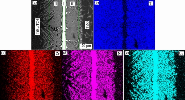
Fig. 4 Interfacial microstructure of TiBw/TC4-Ti60 joint brazed at 940 °C for 10 min (a) and EDS maps of Ti (b), Zr (c), Ni (d) and Cu (e)
To reveal more details of each zone in TiBw/TC4-Ti60 brazed joint, high magnification micrographs were carried out, as shown in Fig. 5, and the EDS analysis was performed to further identify the reaction phases (Table 2). The EDS analysis of the white continuous phase (spot A) in Fig. 5(a) indicated that Ti, Zr, Ni, Cu were the main components, with a molar ratio 2:1 of Ti+Zr to Ni+Cu. According to Cu-Ti-Zr and Ni-Ti-Zr ternary alloy phase diagrams [19-21], it can be determined that the continuous white reaction layer could be concluded as (Ti, Zr)2(Ni, Cu) intermetallic phase. The gray phases in Zone II (marked as B in Fig. 5(b)) and Zone III (marked as D in Fig. 5(c)) had a similar chemical composition and mainly contained element Ti and some amounts of Zr, Ni and Cu, and the gray phases in Zone II and III can be inferred as β-Ti phase due to the high contents of Ni and Cu (β-phase stabilizers). In addition, spots C and E represent the α-Ti phase in TiBw/TC4 composite and Ti60 alloy, respectively. It is evident that the contents of element Zr, Ni and Cu exhibited a slight increase in α-Ti phase because of the diffusion of elements in molten filler alloy into substrates during the brazing process. Moreover, it is noted that the TiB whiskers in TiBw/TC4 composite still remained during brazing and several TiB whiskers detached from TiBw/TC4 composite can be seen in Zone II. Based on the above analyses, the interfacial microstructure of TiBw/TC4-Ti60 joint brazed at 940 °C for 10 min was TiBw/TC4 composite/β-Ti+TiB whiskers/ (Ti,Zr)2(Ni,Cu) intermetallic layer/ β-Ti/ Ti60 alloy.
3.2 Effect of brazing temperature on interfacial microstructure of TiBw/TC4-Ti60 brazed joints
It is accepted that the brazing temperature played an important role in the interfacial microstructure. The BSE images of TiBw/TC4-Ti60 joints prepared at brazing temperature from 900 to 1060 °C for 10 min are shown in Figs. 6(a)-(d), and the interfacial microstructure is evolved obviously with the increase of brazing temperature. When brazing temperature was relatively low (900 or 980 °C), the TiBw/TC4-Ti60 brazed joints comprised three reaction zones (continuous (Ti,Zr)2(Ni,Cu) intermetallic layer and diffusion zones adjacent to the substrates), as shown in Figs. 6(a) and (b). The thickness of (Ti,Zr)2(Ni,Cu) intermetallic layer was decreased because high brazing temperature increased the element diffusion in molten filler alloy into substrates. When increasing the brazing temperature to 1020 °C, the continuous (Ti,Zr)2(Ni,Cu) intermetallic layer disappeared completely, and the brazing seam was occupied by a mixed structure of α-Ti, β-Ti and some scattered white (Ti,Zr)2(Ni,Cu) particles, as shown in Fig. 6(c). With further increasing brazing temperature to 1060 °C, both the (Ti,Zr)2(Ni,Cu) intermetallic layer and diffusion zones disappeared, and the coarse lamellar (α+β) Ti structure was formed on Ti60 side, as shown in Fig. 6(d).

Fig. 5 High magnification backscattered electron images of TiBw/TC4-Ti60 joints brazed at 940 °C for 10 min
Table 2 Chemical compositions (mole fraction, %) and possible phases of each spot marked in Fig. 5
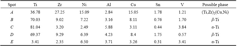

Fig. 6 BSE images of TiBw/TC4-Ti60 joints brazed at different temperatures for 10 min
It can be concluded that the microstructural evolution has a strong relationship with the interdiffusion and reaction of elements between molten filler alloy and the substrates. The interfacial microstructure evolution of TiBw/TC4-Ti60 joints during brazing can be discussed as follows. Firstly, when the brazing temperature exceeded the solidus temperature (Ts) of the amorphous TiZrNiCu filler, the brazing alloy started melting. As the temperature continued to increase the liquidus temperature (Tl), the amount of liquid phase increased continuously until TiZrNiCu filler alloy melted completely. Then, the diffusion of atoms Zr, Ni, Cu and Ti in the liquid phase into both substrates and the dissolution of substrates into liquid phase occurred at the same time. Meanwhile, Ni and Cu atoms can decrease the β-transus temperature of titanium alloys, leading to the transformation of α-Ti into β-Ti during brazing process, as reported by BATRA et al [22] and CREMASCO et al [23]. Therefore, the diffusion zones (Zones II and III) mostly consisted of β-Ti phase when brazing temperature was lower than 1020 °C, which exhibited an approximately-symmetrical morphology, as shown in Fig. 5(a) and Figs. 6(a, b). Besides, the diffusion was not so intense when brazed at relatively low temperatures, so the remnant liquid phase containing large amounts of Zr, Ni, and Cu turned into (Ti,Zr)2(Ni,Cu) intermetallic compounds at the center of brazing seam during cooling process. Nevertheless, the increase of brazing temperature (e.g. 1020 °C and 1060 °C) intensified the diffusion of elements, which resulted in the disappearance of continuous (Ti,Zr)2(Ni,Cu) intermetallic layer, as shown in Figs. 6(c) and (d). Especially, when brazing temperature reached 1060 °C, the (Ti,Zr)2(Ni,Cu) intermetallic compounds disappeared completely and coarse lamellar (α+β)-Ti structures were observed instead. On one hand, the brazing temperature of 1060 °C was higher than the β-transus temperature of Ti60 alloy (~1035 °C [24]), so the α-Ti in Ti60 could be transformed into β-Ti; on the other hand, more β-Ti phase was formed and stabilized due to the diffusion of elements Ni and Cu into the substrates [25,26]. Meanwhile, even though the brazing temperature was higher than the β transus temperature of TC4 alloy, it should be noted that the pining effect of TiB whiskers prevented the grain coarsening in TiBw/TC4 composite, leading to no significant change in TiBw/TC4 substrate at 1060 °C.
3.3 Effect of brazing temperature on joining properties of TiBw/TC4-Ti60 brazed joints
Figure 7 shows the variations of room-temperature shear strength of TiBw/TC4-Ti60 joints with brazing temperature. As brazing temperature increased from 900 °C, the shear strength first increased steadily and then has a substantial growth from 940 to 1020 °C. As the brazing temperature exceeded 1020 °C, the shear strength decreased. The highest average shear strength was 368.6 MPa when the brazing temperature was 1020 °C.
For investigating the relationships between joint properties and interfacial microstructures, SEM and XRD were performed on the fracture surface, and also cross-section BSE images were acquired by rebuilding the fractured joint. Figure 8(a) shows the cross-section BSE image of TiBw/TC4-Ti60 joint brazed at 940 °C for 10 min after shear test. It is obvious that the joint fractured at the continuous (Ti,Zr)2(Ni,Cu) intermetallic layer. Lots of cleavage facets can be observed in the secondary electron (SE) image of fracture surface illustrated in Fig. 8(b). The XRD result, taken from fracture surface as shown in Fig. 8(b), indicates that the (Ti,Zr)2(Ni,Cu) phase dominated on the facture surface [27]. Moreover, the XRD result also reconfirmed the above analyses about interfacial microstructure and phases. It is well known that the continuous intermetallic layers are always detrimental to joining properties due to their nature of brittleness. Hence, the joints brazed below 1020 °C exhibited relatively low shear strength due to the formation of continuous (Ti,Zr)2(Ni,Cu) intermetallic layer in the joints. An increase in brazing temperature can lead to a gradual increase in shear strength, as shown in Fig. 7, which can be attributed to the reduction of (Ti,Zr)2(Ni,Cu) intermetallic compounds.

Fig. 7 Variation of room-temperature shear strength of TiBw/TC4-Ti60 joints with brazing temperature from 900 to 1060 °C
Figure 8(c) shows the cross-section BSE image of TiBw/TC4-Ti60 joint brazed at 1020 °C for 10 min after shear test. It can be seen that the joint fractured in diffusion zone adjacent to TiBw/TC4 substrate. The XRD result and SEM image of fracture surface illustrated in Fig. 8(d) display brittle characteristic and some pulled- out TiB whiskers distributed on the fracture surface. The pulled-out TiB whiskers have the function of supporting part of load during shear test and can increase shear strength to some extent. What is more, according to the interfacial microstructure shown in Fig. 6(c), it is concluded that the disappearance of continuous (Ti,Zr)2(Ni,Cu) intermetallic layer significantly enhanced joint properties. Therefore, the joints brazed at 1020 °C exhibited the highest shear strength. The cross-section BSE image of TiBw/TC4-Ti60 joint brazed at 1060 °C for 10 min after shear test is shown in Fig. 8(e). Combining the XRD result and SE image of fracture surface illustrated in Fig. 8(f), it is determined that the joint mainly fractured on Ti60 substrate side. According to the interfacial microstructure, it is inferred that the coarse lamellar (α+β) structure was harmful to the joint properties. Thus, the shear strength decreased even though there was no continuous (Ti,Zr)2(Ni,Cu) intermetallic layer in joints.

Fig. 8 Fracture analyses of Ti60-TiBw/TC4 brazed joints after shear test
4 Conclusions
1) The interfacial microstructure of Ti60-TiBw/TC4 joints brazed at 940 °C for 10 min was TiBw/TC4 composite/β-Ti + TiB whiskers/(Ti,Zr)2(Ni,Cu) inter- metallic layer/β-Ti/ Ti60 alloy.
2) The microstructural evolution has a strong relationship with the diffusion of elements in molten filler alloy into substrates. The thickness of (Ti,Zr)2(Ni,Cu) intermetallic layer decreased with the increase of brazing temperature and ultimately disappeared at the brazing temperature of 1020 °C. Coarse lamellar (α+β)Ti structure was formed in the Ti60 substrate when brazed at 1060 °C.
3) The presence of continuous (Ti,Zr)2(Ni,Cu) intermetallic layer in joints was harmful to the joining properties, which resulted in low shear strength when brazed below 1020 °C, and the joints preferred to fracture at the (Ti,Zr)2(Ni,Cu) intermetallic layer. The maximum average shear strength of joints reached 368.6 MPa when brazing was conducted at 1020 °C for 10 min. Fracture analyses indicated that cracks propagated in the diffusion zone adjacent to TiBw/TC4 substrate. While further increasing brazing temperature to 1060 °C, the shear strength was decreased due to the formation of coarse lamellar (α+β) structure and the joints fractured on the Ti60 side.
References
[1] LI Y L, FENG J C, HE P. Vacuum brazing of TiAl to 42CrMo steel with Ag-Cu-Ti filler metal [J]. Transactions of Nonferrous Metals Society of China, 2005, 15: 331-334.
[2] LI H X, HE P, LIN T S, PAN F, FENG J C, HANG Y D. Microstructure and shear strength of reactive brazing joints of TiAl/Ni-based alloy [J]. Transactions of Nonferrous Metals Society of China, 2012, 22: 324-329.
[3] YANG Z W, ZHANG L X, HE P, FENG J C. Interfacial structure and fracture behavior of TiB whisker-reinforced C/SiC composite and TiAl joints brazed with Ti-Ni-B brazing alloy[J]. Materials Science & Engineering A, 2012, 532: 471-475.
[4] QIU Q, WANG Y, YANG Z, WANG D. Microstructure and mechanical properties of Al2O3 ceramic and Ti6Al4V alloy joint brazed with inactive Ag-Cu and Ag-Cu+B[J]. Journal of the European Ceramic Society, 2016, 36: 2067-2074.
[5] YUAN B G, ZHENG Y B, WANG Y J, GONG L Q. Hydrogen absorption characteristics and microstructural evolution of TC21 titanium alloy [J]. Transactions of Nonferrous Metals Society of China, 2016, 26: 599-606.
[6] TABRIZI S G, BABAKHANI A, SAJJADI S A, LU W J. Microstructural aspects of in-situ TiB reinforced Ti-6Al-4V composite processed by spark plasma sintering [J]. Transactions of Nonferrous Metals Society of China, 2015, 25: 1460-1467.
[7] HUANG L J, LU C J, YUAN B, WEI S L, CUI X P, GENG L. Comparative study on superplastic tensile behaviors of the as-extruded Ti6Al4V alloys and TiBw/Ti6Al4V composites with tailored architecture[J]. Materials & Design, 2015, 93: 519-526.
[8] CHANG S Y, TSAO L C, LEI Y H, MAO S M, HUANG C H. Brazing of 6061 aluminum alloy/Ti-6Al-4V using Al-Si-Cu-Ge filler metals [J]. Journal of Materials Processing Technology, 2012, 212: 8-14.
[9] SONG X G, CAO J, CHEN H Y, WANG H Q, FENG J C. Contact reactive brazing of Ti53311S alloy using Cu foil as interlayer: Interfacial microstructure and joining properties [J]. Materials & Design, 2013, 46: 895-901.
[10] QIU Q, WANG Y, YANG Z, HU X, WANG D. Microstructure and mechanical properties of TiAl alloy joints vacuum brazed with Ti-Zr-Ni-Cu brazing powder without and with Mo additive [J]. Materials & Design, 2016, 90: 650-659.
[11] WANG Y, QIU Q, YANG Z, WANG D. Microstructure evolution and mechanical properties of Ti-43Al-9V-0.3Y alloy joints brazed with Ti-Zr-Ni-Cu+Mo composite filler [J]. Advanced Engineering Materials, 2016, 182: 488-497.
[12] SONG X R, LI H J, ZENG X. Brazing of C/C composites to Ti6Al4V using multiwall carbon nanotubes reinforced TiCuZrNi brazing alloy [J]. Journal of Alloys and Compounds, 2016, 664: 175-180.
[13] PANG S J, SUN L L, XIONG H P, CHEN C, LIU Y, LI H F, ZHANG T. A multicomponent TiZr-based amorphous brazing filler metal for high-strength joining of titanium alloy [J]. Scripta Materialia, 2016, 117: 55-59.
[14] SHIUE R K, WU S K, CHEN Y T, SHIUE C Y. Infrared brazing of Ti50Al50 and Ti-6Al-4V using two Ti-based filler metals [J]. Intermetallics, 2008, 16: 1083-1089.
[15] SONG X G, CAO J, CHEN H Y, WANG Y F, FENG J C. Brazing TiAl intermetallics using TiNi-V eutectic brazing alloy [J]. Materials Science & Engineering A, 2012, 551: 133-139.
[16] HUANG L J, ZHANG Y Z, GENG L, WANG B, REN W. Hot compression characteristics of TiBw/Ti6Al4V composites with novel network microstructure using processing maps [J]. Materials Science & Engineering A, 2013, 580: 242-249.
[17] LU C J, HUANG L J, GENG L, KAVEENDRAN B, ZHENG Z Z, ZHANG J. Mechanisms behind the superplastic behavior of as-extruded TiBw/Ti6Al4V composites with a network architecture [J]. Materials Characterization, 2015, 104: 139-148.
[18] HUANG L J, GENG L, PENG H X, BALASUBRAMANIAM K, WANG G S. Effects of sintering parameters on the microstructure and tensile properties of in situ TiBw/Ti6Al4V composites with a novel network architecture [J]. Materials & Design, 2011, 32: 3347-3353.
[19] VILLATS P. Handbook of ternary alloy phase diagrams [M]. Materials Park, Ohio: ASM International, 1995.
[20] GANJEH E, SARKHOSH H. Microstructural, mechanical and fractographical study of titanium-CP and Ti-6Al-4V similar brazing with Ti-based filler [J]. Materials Science & Engineering A, 2013, 559: 119-129.
[21] LEE M K, KIM K H, LEE J G, RHEE C K. Growth of isothermally-solidified titanium joints using a multi-component Zr-Ti-Cu-Ni-Be amorphous alloy as a brazing filler [J]. Materials Characterization, 2013, 80: 98-104.
[22] BATRA I S, DEY G K, KULKARNI U D, BANERJEE S. On the sequence of clustering and ordering in a meltspun Cu-Ti alloy [J]. Materials Science & Engineering A, 2003, 360: 220-227.
[23] CREMASCO A, MESSIAS A D, ESPOSITO A R, DUEK E A D R, CARAM R. Effects of alloying elements on the cytotoxic response of titanium alloys [J]. Materials Science & Engineering C, 2011, 31: 833-839.
[24] WANG Q, LIU J, YANG R. High temperature titanium alloysstatus and perspective [J]. Journal of Aeronautical Materials, 2014, 34: 478-481.
[25] CAI X Q, WANG Y, YANG Z W, WANG D P, LIU Y C. Transient liquid phase (TLP) bonding of Ti2AlNb alloy using Ti/Ni interlayer: Microstructure characterization and mechanical properties [J]. Journal of Alloys and Compounds, 2016, 679: 9-17.
[26] SOUZA S A, AFONSO C R M, FERRANDINI P L, COELHO A A, CARAM R. Effect of cooling rate on Ti-Cu eutectoid alloy microstructure [J]. Materials Science & Engineering C, 2009, 29: 1023-1028.
[27] SI X Q, ZHAO H Y, CAO J, SONG X G, TANG D Y, FENG J C. Brazing high Nb containing TiAl alloy using Ti-28Ni eutectic brazing alloy: Interfacial microstructure and joining properties [J]. Materials Science & Engineering A, 2015, 636: 522-528.
宋晓国1,2,张 特2,冯养巨2,檀财旺1,2,曹 健1,张文丛2
1. 哈尔滨工业大学 先进焊接与连接国家重点实验室,哈尔滨 150001;
2. 哈尔滨工业大学(威海) 山东省特种焊接技术重点实验室,威海 264209
摘 要:使用TiZrNiCu 非晶钎料成功实现了TiBw/TC4 复合材料和 Ti60 合金的钎焊连接。通过扫描电子显微镜、能谱仪、X 射线衍射仪及万能材料试验机表征钎焊接头的组织及性能。在940 °C保温10 min下,钎焊接头的典型界面组织为TiBw/TC4 复合材料/ β-Ti+TiB晶须/(Ti,Zr)2(Ni,Cu)金属间化合物层/β-Ti 层/Ti60 合金。钎焊过程中元素向母材中的扩散过程直接影响接头界面结构。钎焊温度的升高使(Ti,Zr)2(Ni,Cu) 金属间化合物层的厚度减小,当钎焊温度超过1020 °C时,(Ti,Zr)2(Ni,Cu)金属间化合物层消失。钎焊温度较低时,生成的脆性相 (Ti,Zr)2(Ni,Cu)不利于接头性能。接头剪切强度随钎焊温度的升高呈先增加后降低的趋势,在1020 °C下获得最大的剪切强度368.6 MPa;而当钎焊温度达到1060 °C时,接头强度降低,这是由于形成了粗大的层状(α+β)-Ti组织。
关键词:钎焊;TiBw/TC4复合材料;Ti60合金;界面结构;断裂
(Edited by Xiang-qun LI)
Foundation item: Projects (51775138, U1537206) supported by the National Natural Science Foundation of China; Project (2015DFA50470) supported by the International Science & Technology Cooperation Program of China; Project (2017GGX40103) supported by the Key Research & Development Program of Shandong Province, China
Corresponding author: Jian CAO; Tel: +86-451-86418882; Fax: +86-451-86418146; E-mail: cao_jian@hit.edu.cn
DOI: 10.1016/S1003-6326(17)60245-0

