Hall-Petch relationship in selective laser melting additively manufactured metals: using grain or cell size?
��Դ�ڿ������ϴ�ѧѧ��(Ӣ�İ�)2021���4��
�������ߣ������ ���� ������ ţ��� ������ Ԭ���� ����
����ҳ�룺1043 - 1057
Key words��additive manufacturing; Hall-Petch relationship; grains; cellular structures; mechanical property
Abstract: The mechanical properties of many materials prepared by additive manufacturing technology have been greatly improved. High strength is attributed to grain refinement, formation of high density dislocation and existence of cellular structures with nanoscale during manufacturing. In addition, the super-saturated solid solution of elements in the matrix and the solid solution segregation along the wall of the cellular structures also promote the improvement of strength by enhancing dislocation pinning. Hence, the existence of cellular structure in grains leads to differences in the prediction of material strength by Hall-Petch relationship, and there is no unified calculation method to determine the d value as grain size or cell size. In this work, representative materials including austenite 316L SS were printed by selective laser melting (SLM), and the strength was predicted. The values of cell size and grain size were substituted into Hall-Petch formula, and the results showed that the calculation error for 316L is increased from 4.1% to 11.9%. Therefore, it is concluded that the strength predicted by grain size is more accurate than that predicted by cell size in additive manufacturing materials. When calculating the yield strength of laser additive manufacturing metal materials through the Hall-Petch formula, the grain size should be used as the basis for calculation.
Cite this article as: WANG Yin, WANG Yue-ting, LI Rui-di, NIU Peng-da, WANG Min-bo, YUAN Tie-chui, LI Kun. Hall-Petch relationship in selective laser melting additively manufactured metals: using grain or cell size? [J]. Journal of Central South University, 2021, 28(4): 1043-1057. DOI: https://doi.org/10.1007/s11771-021-4678-x.

J. Cent. South Univ. (2021) 28: 1043-1057
DOI: https://doi.org/10.1007/s11771-021-4678-x

WANG Yin(����), WANG Yue-ting(������), LI Rui-di(�����), NIU Peng-da(ţ���), WANG Min-bo(������), YUAN Tie-chui(Ԭ����), LI Kun(����)
State Key Laboratory of Powder Metallurgy, Shenzhen Institute of Central South University,Changsha 410083, China
 Central South University Press and Springer-Verlag GmbH Germany, part of Springer Nature 2021
Abstract: The mechanical properties of many materials prepared by additive manufacturing technology have been greatly improved. High strength is attributed to grain refinement, formation of high density dislocation and existence of cellular structures with nanoscale during manufacturing. In addition, the super-saturated solid solution of elements in the matrix and the solid solution segregation along the wall of the cellular structures also promote the improvement of strength by enhancing dislocation pinning. Hence, the existence of cellular structure in grains leads to differences in the prediction of material strength by Hall-Petch relationship, and there is no unified calculation method to determine the d value as grain size or cell size. In this work, representative materials including austenite 316L SS were printed by selective laser melting (SLM), and the strength was predicted. The values of cell size and grain size were substituted into Hall-Petch formula, and the results showed that the calculation error for 316L is increased from 4.1% to 11.9%. Therefore, it is concluded that the strength predicted by grain size is more accurate than that predicted by cell size in additive manufacturing materials. When calculating the yield strength of laser additive manufacturing metal materials through the Hall-Petch formula, the grain size should be used as the basis for calculation.
Key words: additive manufacturing; Hall-Petch relationship; grains; cellular structures; mechanical property
Cite this article as: WANG Yin, WANG Yue-ting, LI Rui-di, NIU Peng-da, WANG Min-bo, YUAN Tie-chui, LI Kun. Hall-Petch relationship in selective laser melting additively manufactured metals: using grain or cell size? [J]. Journal of Central South University, 2021, 28(4): 1043-1057. DOI: https://doi.org/10.1007/s11771-021-4678-x.
1 Introduction
Austenitic 316L stainless steel (SS) is widely investigated because of its widespread application in various industries, including kitchen tools, food industry, medical implants, petrochemical, nuclear power plants, and marine, owing to its excellent corrosion and oxidation resistance [1-4]. In addition, 316L austenitic stainless steel has excellent welding ability due to the low carbon content, and has been used in additive manufacturing (AM) technologies to produce components with fine structure and good mechanical properties [5, 6]. AM is a complex process in which metal parts are fabricated layer-by-layer using three-dimensional (3D) data, involving the coordination among laser system, gas protection system and powder feeding system [7-9]. Among all AM technologies, SLM is the most concerned one since it has relatively high forming accuracy and good surface roughness, and has successfully fabricated metal components with ultrafine-grained structure [10, 11]. Therefore, the 316L SS parts printed by SLM possess excellent comprehensive mechanical properties and good formability [12, 13]. The research on the strengthening mechanism of SLM printed metal materials with high strength has become the focus of researchers.Most of them based on the Hall-Petch formula to explain its strengthening mechanism. However, because of its special and complicated structure including grain and cell, the selection of grain size d value is controversial [14, 15].
Hall-Petch summarized the relationship between the yield strength of a crystal and the grain size, and found that the yield strength of a polycrystal was inversely proportional to the grain size, that is, the smaller the grain, the higher the yield strength, and the larger the grain, the lower the yield strength. The formula is derived based on the dislocation theory [16-19]. When the material deforms, the larger the grains, the larger the number of dislocations and the greater the stress concentration. Therefore, it is easy to activate the source of dislocations of adjacent grains. The expression is as follows [20]:
 (1)
(1)
where ��y is the yield strength; ��0 is the frictional stress determined by the crystal structure and dislocation density; d is the average grain size; and k is the influence coefficient of grain boundary on strength, which is a constant. It is worth noting that the effect of the cell boundary on the material is similar to that of the grain boundary, and it also hinders the movement of dislocations.
Since the strength of aluminum alloy prepared by the traditional processing method is much lower than that of SLM, many researchers have studied the strengthening mechanism of SLM components. XI et al [21] studied Al-12Si alloys prepared by SLM and found that the main reason for the high strength of SLM printed aluminum alloys was the presence of a large number of cell grains. The barriers of dislocation motion and pinning effect will be greatly enhanced as the number of cell boundaries increases, and thus the dislocation movement requires greater applied stress, inducing the elevated yield strength. Therefore, the yield strength of SLMed Al-12Si alloys calculated by cell size is increased by 76 MPa compared with the strengthening value calculated by grain size. On the contrary, JIA et al [22] believed that the strength improvement of SLM printed aluminum alloy is not the only obstacle of grain boundary to the movement of high-density dislocations, the solid solution strengthening and modulus hardening also matter.The strength of SLM printing aluminum alloy, therefore, should be predicted by grain size rather than that of cell. At the same time, the same controversy exists in the 316L stainless steel prepared by SLM. WANG et al [15] estimated the strength of SLM 316L stainless steel by Hall-Petch formula, and the cell size was used to replace the value of d.The calculated strength was 516 MPa, accounting for a substantial portion of the actual value of 590 MPa.Hence, it was believed that the existence of solidification cellular structure was the major contributor of high strength for SLM 316L stainless steel. However, BAHL et al [16] thought that there are certain critical issues using the cell size to calculate the strength of SLM 316L stainless steel. This calculation method has some defects in the selection of the value of Hall-Petch constant k and the contribution of high-density dislocations to the strength of materials is ignored. The improved Hall-Petch formula is as follows:
 (2)
(2)
where the M��Gb is dislocation strengthening factor and the value of d was replaced with the conventional grain size.
In the present investigation, the strengthening mechanisms of parts prepared by SLM were mainly studied based on the Hall-Petch formula to predict SLMed parts mechanical strength. Grain and cellular microstructures of SLM printed 316L stainless steel were characterized by SEM and EBSD, and the yield strength of alloy was obtained. The relationship between grain/cell size and Hall-Petch formula were studied. Besides, SLM printed pure aluminum and AlSi10Mg were characterized by EBSD and their tensile properties were also calculated, in order to prove the general applicability of the calculation method.
2 Materials and method
2.1 Specimen preparation
Spherical gas atomized powder was in-house prepared by a vacuum induction gas atomisation (VIGA) process. The main chemical compositions of the developed 316L SS, pure Al (99.9%) and AlSi10Mg alloy powder reported on herein were determined by inductively coupled plasma atomic emission spectrometry (ICP-AES), as listed in Table 1. After sieving, the powders within the size distribution ranging from 15 to 61 ��m were processed with SLM using a FS271 machine (Farsoon, Inc, China), equipped with a 500-W Gaussian beam fiber laser at a laser beam diameter of 90 ��m. The bidirectional scanning strategy with a 67�� angle rotation between adjacent layers was applied. After a series of optimization of SLM process parameters, samples of three different components, including 316L SS, pure Al and AlSi10Mg alloy, were printed with an optimal laser power (P), scan speed (S), hatch distance (H) and layer thickness (L). The SLM process parameters are listed in Table 2. Through the analyses of Archimedes method on the samples printed with these applied parameters, it was found that the relative density of these samples is over 98.1%.
Table 1 Chemical composition of the raw powder
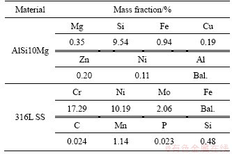
Table 2 SLM print parameters
2.2 Materials characterization
For microscopy analysis, the specimens, including pure aluminum, AlSi10Mg, and 316L SS, were systematically ground and polished to a mirror, etching with corrosive liquid at the last stage.
Subsequently, a field emission scanning electron microscope (FESEM NanoLab600i, Germany) operated at 15 kV was used for microstructure observation. Electron backscattering diffraction (EBSD) was employed for the examination of grain size using a FEI NanoLab600i microscope equipped with an EDS detector. The step size of the EBSD measurements was 1.5 ��m. The grain/cell morphologies and EDS mapping were viewed through filed emission scanning electron microscope (FEI NanoLab600i SEM). Transmission electron microscope (TEM) was employed for a detailed analysis of dislocation morphologies, using a FEI Tecnai G2 F20C zech microscope equipped with high resolution transmission electron microscope (HR-TEM) and operated at 200 kV. TEM specimens were prepared by standard electrochemical polishing procedures.
Microhardness and tensile samples were cut along the laser scanning direction. Microhardness was evaluated on the whole cross section with Vickers microhardness tester, subjecting to a load of 50 g and a dwell time of 15 s. The tensile tests were carried out at a strain rate of 1��10-3 s-1 with a roboticizedtesting machine (MTS system, Eden Prairie, MN, USA) at room temperature.
3 Results
3.1 Microstructure of SLMed 316L SS
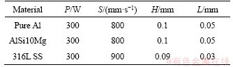
Rapid cooling rate generated in the SLM process results in an ultrafine cellular structure in the as-printed 316L.These cells are austenite iron matrix decorated with networks of dislocation networks. Figure 1 presents an SEM morphology of a SLMed 316L sample observed by electron channeling contrast imaging (ECCI) test. It was produced by FS271 SLM machine (Farsoon, Inc, China), using mature process parameters (for 316L), laser powder 300 W, scan velocity 900 mm/s, hatch distance 0.09 mm, and layer thickness 0.03 mm. The ECCI image shown in Figure 1(a) clearly reveals the obvious microstructure features of the SLM printed sample, including half-cylindrical molten pool and molten pool boundary, with width of molten pool ranging from 60 to 100 ��m. A large number of columnar grains growing towards the center of molten pool constitute a typical molten pool morphology. Figure 1(b) shows the enlarged image of the characteristic areas in Figure 1(a). It clearly reveals that columnar grains are composed of neatly arranged or netlike nano-sized cells. Various structures appear on different columnar grains due to the difference of solidification conditions, that is thermal gradient, cool rate, including the reticular structure (dislocation cell) and the columnar structure (dislocation wall). The reasons for the formation of the cellular structure will be discussed further.
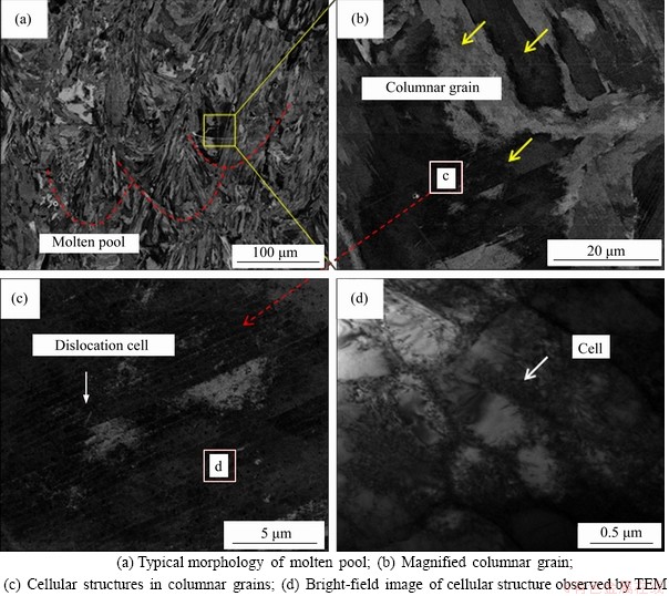
Figure 1 Backscattered electron images in SEM of 316L SS microstructures produced by SLM:
The cellular structure of the columnar grains is shown in Figure 1(c). The dislocation walls are clearly visible in parallel and decorated with nanoscale cells. In order to see the structure of the cells more clearly, TEM was used to observe a small part of the cells. Figure 1(d) is the bright field image of the cells. The results show that the cell boundary is composed of a large number of entangled dislocations, and many dislocations also exist inside the cell. PENG et al [23] observed the substructure of the as-printed 316L SS material through TEM and found that the cell boundary is composed of a large number of entangled dislocations, divided into dislocation wall and dislocation cell according to their shapes. Due to the continuous heat circulation in the printing process, local tensile stress is formed. The joint action of tensile residual stresses coupled with thermal strain generation results in the formation of the dislocation networks [14]. WANG et al [15] proved the element segregation of Mo and Cr along the walls of cellular structures during the process. Although the materials are printed in different ways, the microsegregation of Mo and Cr still exists [24]. Therefore, we posit that the cell boundary is mainly composed of entangled dislocation structure coupled with Mo and Cr clusters.
Figure 2(a) displays the engineering stress-strain curves of as-printed 316L SS. The yield strength, tensile strength and total elongation of as-printed 316L SS were detected as 559.56 MPa, 674.56 MPa and 41.8%, respectively. In the recent study, the higher strength in a series of materials prepared by SLM has been widely reported. The source of strengthening has attracted the attention of many researchers. The research focuses mainly on the effect of cellular structures and dislocation network on the yield strength improvement of printing materials, which is explained based on Hall-Petch formula. However, in the current reports, there are differences in the calculation of yield strength of materials by Hall-Petch formula [15, 16]. Some researchers believe that cellular structures contribute more to the strength than grains and that cell size should be used to calculate the yield strength of materials, while others do not. In this study, we posit that the cell boundary is mainly composed of entangled dislocation, and the strengthening of the cellular structure can be summarized as the dislocation strengthening system. In other words, the main contribution of the existence of cellular structures in printing materials is to enhance the dislocation. Therefore, the strength of printed 316L SS is mainly considered in the following part. In addition, the effects of defects such as pores and microcracks on the material strength cannot be ignored.
Figure 2 Engineering stress-strain curves (a) and predicted strength values of printed samples (b)
In this case, solid solution hardening, grain boundary strengthening and dislocation strengthening are considered the main strengthening mechanisms affecting the SLMed 316L. Considering the present scenario, the yield strength could be calculated as:
 (3)
(3)
 (4)
(4)
 (5)
(5)
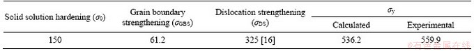
where ��y is the yield strength; the factors ��0, ��GBS and ��DS represent the contribution of the friction stress and solid solution hardening, grain boundary strengthening, and dislocation strengthening to the yield strength, respectively and ��0 is about 150 MPa;k is the Hall-Petch parameter (approximately 300 MPa����m1/2 [15]); d is the average grain size; M is the orientation factor (approximately 2.20 [16]); �� is a constant (approximately 0.3); G is shear modulus (78 GPa); b (0.25 nm) is Burgers vector.
It can be seen from Figure 1 that the grain morphologies are different, with different elongations along the construction direction, which has a certain influence on the statistics of grain size. Thus, the effective average grain size of a grain is calculated using EBSD. The effective grain size is estimated to be around 24 ��m for the as-printed 316L samples, and dislocation density is selected to be around 6��1014 m-2 [16]. Grain size and dislocation density are substituted into the equation to calculate the yield strength of the material. The calculated yield strength value is 536.2 MPa, which is basically consistent with the experimental value of 559.56 MPa. However, it is inevitable that there will be a difference between the predicted value and the experimental value because of the defects and grain morphology. Table 3 presents the contributions of solid solution hardening, grain boundary strengthening and dislocation strengthening of samples. Then, the effective average size of the cells (400 nm) is also substituted into the equation, and the strength of the sample is calculated to be 626.19 MPa. It is worth noting that the dislocation strength should be removed when the cell size is used to predict the material strength. The predicted value obviously exceeds the experimental value, which is related to the cause of the formation of cells. Figure 2(b) shows the relationship between the material strength calculated by the two calculation methods and the experimental value. A total of four groups of tensile samples were prepared, corresponding to different yield strength predictions, and marked as one group with the same pattern. It is obvious that the predicted value obtained after the substitution of grain size into the equation is more in line with the practical significance. By calculating the percentage error between the predicted and experimental values, it can be found that the strength predicted by cell size is increased from 4.1% to 11.9% compared with the strength predicted by grain size. The relative density of the printed 316L in this work is 98.94%.
Table 3 Contributions of various strengthening mechanisms (MPa)
3.2 Microstructure of SLMed Al-alloy
To further illustrate the reliability of the above calculation method, pure aluminum and AlSi10Mg are subsequently printed by SLM. Figure 3 displays the vertical-sectional SEM images of the etched Al parts fabricated by SLM. In the microstructure of SLMed Al in Figure 3(a), pores still exist at the molten pool boundary after rapid melting and solidification. Pores are introduced resulting from the low melting point of Al, the disappearance of entanglement dislocations after corrosion and the high viscosity of pure aluminum at the late solidification stage, which makes it too late to replenish the pores among secondary dendrites [25]. Besides, columnar dendrites grow along the center of the pool and are connected to the columnar grains in the upper layer, which demonstrates that typical non-equilibrium microstructures can be observed in the SLMed Al part, as shown in Figure 3(a) and the magnified version of Figure 3(b). Figure 3(c) reveals that cellular substructures constitute the columnar crystals. Similar findings were also found in the pure copper printed by HUANG et al [26]. However, the formation of cellular structural was not discussed.
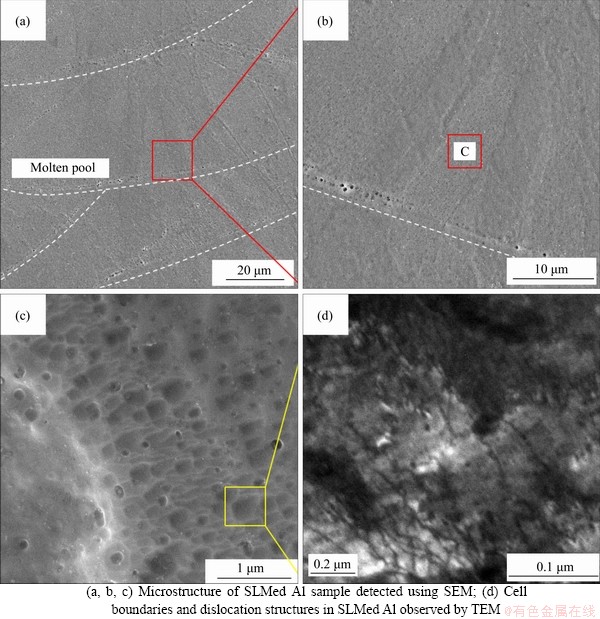
Figure 3 Microstructure of SLMed Al:
The formation of dislocation cell structures in the metal material through multiple slip deformation is a well-known phenomenon, whose formation mechanism has been proved. There are many theories that can support the formation of cellular substructures owing to the formation of a large number of dislocations in metal materials after multiple slip deformation [27-29]. However, because of the rapid cooling mechanism of SLM components in the printing process, a great deal of internal residual stress is generated, which can also promote the formation of this substructure. Figure 3(d) shows a bright-field (BF) microstructure of the SLMed Al, revealing that the grain boundary of the cellular structure in the SLMed Al is composed of numerous entangled dislocations. RAMIREZ et al [30] believed that it is extremely unlikely for cellular solidification to occur in SLMed pure Cu, and reported that copper oxide precipitates exist at the boundary of cell. To analyze the chemistry of the printed pure aluminum cell boundary, energy dispersive X-ray spectroscopy (EDS) in the scanning TEM (STEM) was employed and the results are shown in Figure 4.
It is revealed that there is no segregation of other elements in the cell boundary, in which the percentage of aluminum is 99.8%, the content of Si is 0.15%, and the content of Mg is 0.5%. Thus, the printed pure aluminum cell boundary mainly consisted of a large number of entangled dislocations, containing trace amounts of other elements. But the existence of oxides has not been proved.
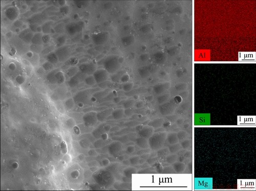
Figure 4 EDS mapping of Al, Mg and Si in SLMed pure Al sample
Solid solution strengthening is not involved in the pure aluminum alloy, so it should be abandoned when considering the contribution of strengthening to yield strength. However, a large number of dislocations can be observed in the microstructure as shown in Figure 3(d). Therefore, the dislocation strengthening mechanism is an important factor to improve the strength of the printed pure aluminum. In this work, the reason for the improvement of the strength of the printed pure aluminum relative to casting is the hindrance of boundary of grains and cells to dislocation. However, it is not clear that whether the grain boundary or cell boundary plays the main role in the printed pure aluminum although it has been confirmed that the grain boundary is the main factor in the strength simulation of printed 316L parts. The yield strength (��y) of SLMed pure Al can thus be expressed:

where ��0 is the tensile strength of pure Al (taken as 35 MPa [31]); k is the Hall-Petch slope constant, which is different from casting pure aluminum due to the fact that the grain size of printed pure aluminum is small. Thus, 130 is chosen to be the value of the Hall-Petch slope k [32].
The tensile strength of printed pure aluminum is predicted by input of average grain/cell size. Using EBSD data, the effective sizes of grain and cell are 6 ��m and 0.3 ��m, respectively. The predicted tensile strength are 88.06 MPa and 211.60 MPa for the grain size and cell size, respectively. Subsequently, these strength values (��y) are converted to hardness values (H) as follows:
3H=��y
Therefore, the hardness values of the predicted printed pure Al are HV 29.35 and HV 70.53, respectively. The hardness of HV 29.35 calculated by grain size is in good agreement with the experimental value of HV 32.32, as shown in Figure 5. This calculation result is consistent with the calculation result of printed 316L in the previous section. Regardless of the complexity of grain boundary composition, it is more accurate to predict the printed pure Al strength with grain size. In order to further prove the reliability of this viewpoint, the grain boundary structure of AlSi10Mg alloy was analyzed and the strength was predicted.
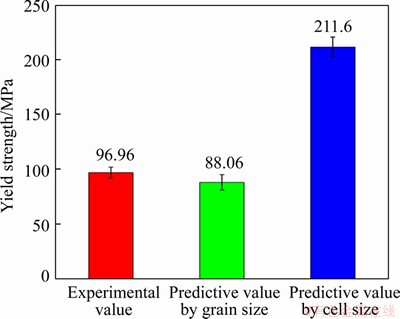
Figure 5 Calculated value and experimental yield strength of SLMed pure Al
The predictions of the strength of as-printed 316L SS and pure Al were discussed above based on the hindrance of grain boundary to dislocation. The predicted values obtained by substituting grain size into Hall-Petch formula are more in line with experimental values than those by cell size. However, neither of the two materials discussed above contributes to grain boundary element precipitation, eutectic strengthening and solid solution strengthening to the strength of printed materials. Therefore, the prediction and calculation of the strength of the printed AlSi10Mg alloy will be discussed below.
The surface morphologies of the SLMed AlSi10Mg alloy along the yz direction are presented in Figure 6. A typical molten pool morphology of fish scale pattern can be observed and a small number of circular holes are distributed around the molten pool (Figure 6(a)). The pores are mainly caused by incomplete filling of the pores between adjacent printed layers and insufficient filling of the pores between adjacent secondary dendrites at the late solidification stage [33]. Figure 6(b) shows the special grain morphology inside the molten pool due to the rapid cooling mechanism and steep thermal gradients during the laser process. The special forming environment of the sample results in local microstructures that differ from traditional manufacturing methods such as casting. The molten pool is composed of a large number of grains orienting towards the building direction, while a large number of eutectic cellular networks are composed of grains [34]. The length scales of the melt pool are hundreds of microns, while the diameters of grains are generally between 2 and 8 ��m. Besides, we found that the grain sizes in different pools are different. Therefore, in order to obtain a representative average grain size, the average grain size measured by EBSD is (3.7��2.8) ��m. The local enlarged image of molten pool in Figure 6(c) shows the eutectic cellular network with an average size of (500��120) nm. Most of Al cells usually appear equiaxed in the SLMed AlSi10Mg along the melt pool core direction. Besides, cell boundaries decorated by eutectic belts possess nanoscale characteristics, which are formed by precipitated Si elements under rapid cooling condition [33]. ALGHAMDI et al [35] observed that these eutectic belts with nanometer characteristics are rich in Si and Mg elements by EDS.
To analyze the distribution of Al, Si and Mg elements in the eutectic cellular network, energy dispersive X-ray spectroscopy (EDS) in the scanning TEM (STEM) was employed and the results are shown in Figure 6.It can be found that Si clusters exist in the microstructure. Meanwhile, the ��-Al matrix is surrounded by eutectic Si walls. Moreover, Mg element is segregated along eutectic walls and intermetallic eutectic compounds (Mg2Si) with Si elements forms.
The hardness values of the SLMed AlSi10Mg material, including experimental value and calculated values, are shown in Figure 7. The SLMed AlSi10Mg sample has a hardness of HV 146.19, which is higher than HV 136 of the sample prepared by KEMPF et al [36]. The effect of dislocation strengthening on the material strength improvement cannot be ignored, which is manifested as the interaction between adjacent dislocations [37]. The cell boundary composition of SLM printed AlSi10Mg alloy material is different from that of printed pure Al and 316L stainless steel. Through the detection of cell boundary components, the complexity of cell boundary of printed AlSi10Mg can be revealed, and it is mainly composed of precipitated Si particles, Mg2Si intermetallic eutectic compounds and entangled dislocations [36]. The formation of cell structure in printed materials plays an important role in the improvement of material strength, but all of them act as a hindrance to dislocation. In other words, the existence of cellular microstructure is the manifestation of dislocation strengthening enhancement relative to grain boundary. Therefore, when the Hall-Petch formula is used to predict material strength, the value of d size in the formula is still dominated by grain size rather than cell size. Then the yield strength of the material is about 438.57 MPa according to the 3H=��y. The reasons for applying the modified Hall-Petch to predict the strength of the printed material are as follows: Because in addition to the grain boundary strengthening (GBS), other strengthening mechanisms such as Orowan strengthening (OS) and solid solution strengthening (SSS) are likely to be contributing to the overall strength in our SLMed AlSi10Mg material due to the organizational complexity [37-39]. The overall yield strength of SLMed AlSi10Mg can be expressed as:
 (7)
(7)
where ��' is the yield stress of pure Al (taken as 35 MPa [32]); ��GBS is the grain boundary strengthening; ��SSS is the solid solution strengthening; ��OS is the Orowan strengthening. The Hall-Petch equation calculates the strengthening induced by boundary hindrance to dislocation motion:
 (8)
(8)
where ��GBS is the increase in yield strength on the grain boundary strengthening and ��0is the lattice friction stress (taken as 125 MPa); k is the Hall-Petch constant about 50 MPa for AlSi ultrafine grain alloys [40]; d is the effective average grain size which is 4.7 ��m by EBSD. The total contribution of grain boundary is calculated to be 148.15 MPa. As such, the contribution to the increment in yield strength induced by solid solution strengthening can be calculated as below:
 (9)
(9)
where Ax is the constant related to the solution mode of elements in Al matrix and C0 is the concentration of the solute element in mass fraction. The solubility of Si element in printed aluminum alloy is between 6 wt % and 8 wt %, which forms a supersaturated solution structure [35]. In addition, the contribution of SSS in AlSi10Mg is also from Cu, Mg, Zn and Mn. Here we used the minimum value of 68 MPa of elemental solid solution strengthening from Al 7055 high-strength aluminum alloys [41]. As such, the stabilized Mg2Si phase and the nano-size Si particles with close spacing can improve the alloy strength through Orowan strengthening mechanism [42]. The relevant particle involved Orowan strengthening can be expressed as follows [43]:
 (10)
(10)
where G is the shear modulus, which is 26.5 GPa for the Al matrix; b is the constant of the Burgers vector (~0.286 nm for Al); and L is the average distance between nano-particles. The average particle spacing of 84 nm was selected, referring to the value of AlSi10Mg alloy printed by FITE et al [34] at an annealing temperature of 170 ��C. The value of Orowan strengthening resulting from Si and Mg2Si precipitates (estimated using Orowan strengthening formula) is 180 MPa.
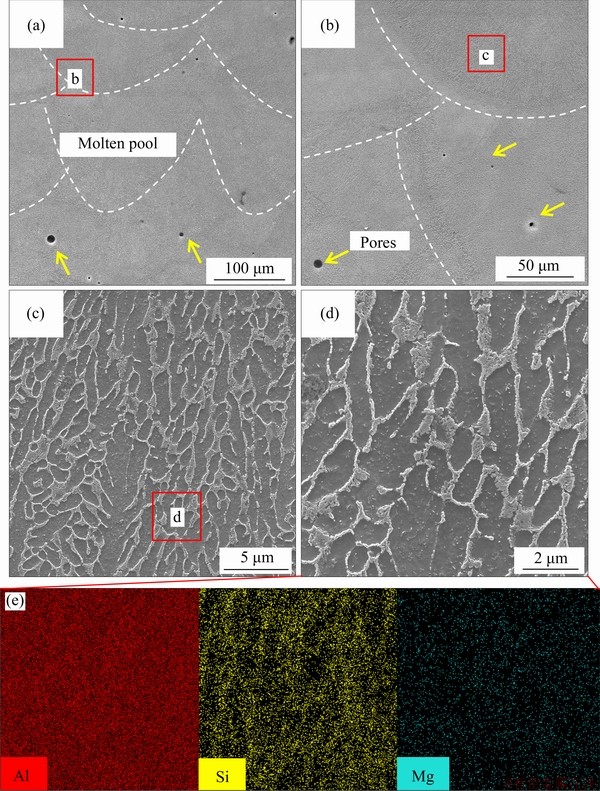
Figure 6 STEM microstructure of SLMed AlSi10Mg and cellular structure at two magnifications along with EDS mapping of Al, Si, and Mg
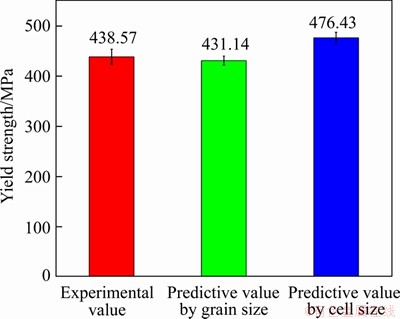
Figure 7 Calculated and experimental yield strength of SLMed AlSi10Mg
Thus, the total expected yield strength of the as-printed AlSi10Mg induced by the combination of these various strengthening mechanisms can be calculated from the overall yield strength formula, which is 431.14 MPa. The calculated value is very close to the experimental value of 438.57 MPa. FITE et al [34] believed that the contribution of cell grain boundary to material strength is greater than that of grain size, and thus cell size could better reflect the improvement of printing material strength than grain size. Therefore, the cell size of 500 nm is also used to predict the strength of the printed material. Combined with various strength contributions, the predicted strength of the material is 476.43 MPa. By calculating the percentage error between the predicted and experimental values, it is found that the predicted strength by cell size is increased from 1.6% to 10.3% compared with the predicted strength by grain size. In general, it is possible to predict the strength of a printed material using either grain size or cell size, but grain size is relatively more accurate.
4 Discussion
For polycrystalline materials, it can be proved that the external shear stress has a linear relationship with the reciprocal of the square of grain diameter, namely the Hall-Petch relationship. The derivation of Hall-Petch model is based on the dislocation accumulation at the grain boundary. The structure near the grain boundary is irregular and the dislocation source is easy to form. Therefore, based on the dislocation pile-up model, the grain diameter can be deduced as follows:
 (11)
(11)
where ��0 is the stress when the dislocation stacking in the grain is basically completed and the applied shear stress reaches the yield point of the material, which is only related to the dislocation motion; n is the number of dislocations of the pile-up under the shear stress; D is the number associated with the type of dislocation. Furthermore, when the applied shear stress is greater than the resistance of the grain boundary to dislocation motion, the dislocation source in the grain begins to move and dislocation pile-up is formed at the boundary. Therefore, by analyzing the minimum critical shear stress required for the dislocation source to move, the yield stress can be calculated as follows [44]:
 (12)
(12)
where �ӡ� is the minimum comprehensive shear stress used to enable the crystal material to overcome the resistance to slip except dislocation pile-up, and is a constant related to the material; D is a number that depends on the type of dislocation; ��c is the shear stress required for the dislocation source to move; S is a quantity that is related to crystal lattice type, grain boundary type and the degree of partial interstitial atom clustering along the grain boundary [45, 46]. It should be noted that the value of D is the distance of effective dislocation movement, which is the size of grain.
Based on the above analysis, it can be concluded that the prediction of material strength based on the dislocation pile-up model is more accurate. In addition, the strengthening mechanism in the metal alloy is often accompanied by other strengthening mechanisms contributing to the material strength. In this work, the rapid heating and cooling during the SLM process lead to the production of cellular structure [16, 24, 36, 37, 39]. Therefore, the effect of microstructure on mechanical properties was studied. Two different sizes including grain size and cell size were substituted into the Hall-Petch formula to predict the strength of the material. The results show that the grain size is more accurate than the cell size in predicting the material strength, and the reason is related to the dislocation motion discussed earlier. In Figure 1(d) and Figure 3(d), columnar grains consisting of dislocation-decorated cellular structures are revealed, and there are also considerable dislocation lines existing within the cell. The formation of cellular structure significantly contributes to the strength of printing materials. Dislocations are affected by the cell wall in the process of movement, because there are a lot of entangled dislocations, precipitates and strengthening phases in the cell wall. Therefore, the bypassing and cutting of dislocations will occur [36].
However, under external stress, most of the dislocations and the dislocations without entanglement in the cell wall will be aligned and move to the grain boundary in the form of dislocation lines. The generation of cell structure does enhance the strength of the SLMed materials, and also provide a high-speed diffusion channel for the diffusion of elements within the matrix, intensifying the dislocation enhancement to the material strength, but it cannot be used as a basic unit of material composition. Therefore, in order to predict the strength of the printed material more accurately, the value of grain size should be considered the value of d rather than the size of the cell. The comparison between the predicted and experimental strength of the printed Mg alloy, Ti alloy, Al alloy and 316L stainless steel is summarized below. The predicted strength is calculated by grain size, as shown in Figure 8.
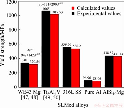
Figure 8 Calculated and experimental yield strength values of SLMed WE43 Mg, Ti6Al4V, 316L SS and Al alloys
5 Conclusions
Materials prepared by 3D printing possess high strength, such as 316L stainless steel and aluminum alloy printed, attributing to its special structure under the rapid heating and cooling process, including ultra-fine grains, high-density dislocation and nano-scale cellular structure. The wall of the cell structure is composed of a large number of entangled dislocations or precipitated phases, and the formation of the cell structure provides a high-speed diffusion channel for elements. In this work, the Hall-Petch formula was used to predict the yield strength of the printing material. The grain size and cell size were selected as the sizes of the d value. However, it is worth noting that the Hall-Petch formula is modified when multiple strengthening mechanisms jointly contribute to the strength of printed materials. The grain size and cell size of 316L stainless steel are 24 ��m and 400 nm, respectively. The strength calculation error predicted by grain size is 4.1%, far less than the strength calculation error predicted by cell size (11.9%). Yield strength is predicted by grain size with an error of 1.6% and by cell size with an error of 10.3% in printed AlSi10Mg alloys. In addition, the yield strength of the printed Mg alloy and Ti alloy was summarized, and the yield strength predicted by the grain size is in good agreement with the experimental value. One may generally conclude from above part that when evaluating the strength of printing materials by Hall-Petch relationship, the result calculated by grain size is closer to the experimental value with the minimum error.
Contributors
The overarching research goals were developed by WANG Yin, LI Rui-di, YUAN Tie-chui, and LI Kun. WANG Yin, NIU Peng-da, and WANG Yue-ting provided the measured raw data, and analyzed the measured data. WANG Yin and WANG Min-bo established the models and calculated the predicted strength. WANG Yin and LI Rui-di analyzed the calculated results. The initial draft of the manuscript was written by WANG Yin. All authors replied to reviewers�� comments and revised the final version.
Conflict of interest
WANG Yin, WANG Yue-ting, LI Rui-di, NIU Peng-da, WANG Min-bo, YUAN Tie-chui and LI Kun declare that they have no conflict of interest.
References
[1] AL-MANGOUR B, MONGRAIN R, IRISSOU E, YUE S. Improving the strength and corrosion resistance of 316L stainless steel for biomedical applications using cold spray [J]. Surface and Coatings Technology, 2013, 216: 297-307. DOI: 10.1016/j.surfcoat.2012.11.061.
[2] AHMADI A, MIRZAEIFAR R, MOGHADDAM N S, TURABI A S, KARACA H, ELAHINIA M. Effect of manufacturing parameters on mechanical properties of 316L stainless steel parts fabricated by selective laser melting: A computational framework [J]. Materials and Design, 2016, 112: 328-338. DOI: 10.1016/j.matdes. 2016.09.043.
[3] ZHONGYuan,RANNARL E, LIULei-feng,KOPTYUGA, WIKMAN S, OLSEN J, CUI Da-qing, SHEN Zhi-jian. Additive manufacturing of 316L stainless steel by electron beam melting for nuclear fusion applications [J]. Journal of Nuclear Materials, 2017, 486: 234-245. DOI: 10.1016/ j.jnucmat.2016.12.042.
[4] ALMANGOUR B, KIM Y K, GRZESIAK D. Novel TiB2-reinforced 316L stainless steel nanocomposites with excellent room- and high-temperature yield strength developed by selective laser melting [J]. Composites Part B: Engineering, 2019, 156(1): 51-63. DOI: 10.1016/ j.compositesb.2018. 07.050.
[5] JOHNSON L, MAHMOUDI M, ZHANG Bing, SEEDE R, HUANG Xue-qin, MAIER J T, MAIER H J, KARAMAN I, ELWANY A. Assessing printability maps in additive manufacturing of metal alloys [J]. Scripta Materialia, 2019, 176(1): 199-210. DOI: 10.1016/j.actamat.2019.07.005.
[6] SONG Bo, ZHAO Xiao, LI Shuai, HAN Chang-jun, WEI Qing-song, WEN Shi-feng, LIU Jie, SHI Yu-sheng. Differences in microstructure and properties between selective laser melting and traditional manufacturing for fabrication of metal parts: A review [J]. Frontiers of Mechanical Engineering, 2015, 10(2): 111-125. DOI: 10.1007/s11465-015-0341-2.
[7] ZINOVIEVA O, ZINOVIEV A, PLOSHIKHIN V. Three-dimensional modeling of the microstructure evolution during metal additive manufacturing [J]. Computational Materials Science, 2018, 141: 207-220. DOI: 10.1016/ j.commatsci. 2017.09.018.
[8] LINKai-jie, GUDong-dong, XILi-xia,YUANLu-hao, NIU Song-qiao, LV P, GE Qing. Selective laser melting processing of 316L stainless steel: Effect of microstructural differences along building direction on corrosion behavior [J]. The International Journal of Advanced Manufacturing Technology, 2019, 104(5-8): 2669-2679. DOI: 10.1007/ s00170-019-04136-9.
[9] LI Rui-di, NIU Peng-da, YUAN Tie-chui, CAO Peng, CHEN Chao, ZHOU Ke-chao. Selective laser melting of an equiatomic CoCrFeMnNi high-entropy alloy: Processability, non-equilibrium microstructure and mechanical property [J]. Journal of Alloys and Compounds, 2018, 746: 125-134. DOI: 10.1016/j. jallcom.2018.02.298.
[10] MURR L E, GAYTAN S M, RAMIREZ D A, MARTINEZ E, HERNANDEZ J, AMATO K N, SHINDO P W, MEDINA F R, WICKER R B. Wicker. Metal fabrication by additive manufacturing using laser and electron beam melting technologies [J]. Journal of Materials Science & Technology, 2012, 28(1): 1-14. DOI: 10.1016/ S1005-0302(12)60016-4.
[11] LI Rui-di, WANG Min-bo, LI Zhi-ming, CAO Peng, YUAN Tie-chui, ZHU Hong-bin. Developing a high-strength Al-Mg-Si-Sc-Zr alloy for selective laser melting: Crack-inhibiting and multiple strengthening mechanisms [J]. Acta Materialia, 2020, 193: 83-98. DOI: 10.1016/j.actamat. 2020.03. 060.
[12] JEON J M, PARK J M, YU Ji-hun, KIM J G, SEONG Y, PARK S H,KIM H S. Effects of microstructure and internal defects on mechanical anisotropy and asymmetry of selective laser-melted 316L austenitic stainless steel [J]. Materials Science and Engineering A, 2019, 763: 138152. DOI: 10.1016/j.msea. 2019.138152.
[13] ZHANG Zheng-yan, CHU Bei-bei, WANG Lei, LU Zhong- hua. Comprehensive effects of placement orientation and scanning angle on mechanical properties and behavior of 316L stainless steel based on the selective laser melting process [J]. Journal of Alloys and Compounds, 2019, 791: 166-175. DOI: 10.1016/j.jallcom.2019.03.082.
[14] ZHU Z G, NGUYEN Q B, NG F L, AN X H, LIAO X Z, LIAW P K, NAI S M L, WEI J. Hierarchical microstructure and strengthening mechanisms of a CoCrFeNiMn high entropy alloy additively manufactured by selective laser melting [J]. Scripta Materialia, 2018, 154(9): 20-24. DOI: 10.1016/j.scriptamat. 2018.05.015.
[15] WANGYM, VOISINT, MCKEOWNJT, YEJ, CALTA N P, LI Z, ZENG Z, ZHANG Y, CHEN W. Additively manufactured hierarchical stainless steels with high strength and ductility [J]. Nature Materials, 2018, 17(1): 67-71. DOI: 10.1038/nmat5021.
[16] BAHL S, MISHRA S, YAZAR K U, KOLA I R, CHATTERJEE K, SUWAS S. Non-equilibrium microstructure, crystallographic texture and morphological texture synergistically result in unusual mechanical properties of 3D printed 316L stainless steel [J]. Additive Manufacturing, 2019, 28: 65-77. DOI: 10.1016/j.addma. 2019.04.016.
[17] LI J C M, CHOU Y T. The role of dislocations in the flow stress grain size relationships [J]. Metallurgical & Materials Transactions B, 1970, 1(5): 1145-1159. DOI: 10.1007/ BF02900225.
[18] CHIA K H, JUNG K, CONRAD H. Dislocation density model for the effect of grain size on the flow stress of a Ti�C15.2 at.% Mo ��-alloy at 4.2�C650 K [J]. Materials Science and Engineering A, 2005, 409(1, 2): 32-38. DOI: 10.1016/j.msea. 2005.03.117.
[19] KUBIN L P, MORTENSEN A. Geometrically necessary dislocations and strain-gradient plasticity: A few critical issues [J]. Scripta Materialia, 2003, 48(2): 119-125. DOI: 10.1016/S1359-6462(02)00335-4.
[20] KASHYAP B P, TANGRI K. On the Hall-Petch relationship and substructural evolution in type 316L stainless steel [J]. Acta Metallurgica et Materialia, 1995, 43(11): 3971-3981. DOI: 10.1016/0956-7151(95)0011 0-H.
[21] XI L X, ZHANGH, WANGP,LIH C, PRASHANTH K G, LIN K J, KABAN I, GU D D.Comparative investigation of microstructure, mechanical properties and strengthening mechanisms of Al-12Si/TiB2, fabricated by selective laser melting and hot pressing [J]. Ceramics International, 2018, 44(15): 17635-17642. DOI: 10.1016/j.ceramint.2018.06.225.
[22] JIA Qing-bo, ROMETSCH P, KURNSTEINER P, CHAO Qi, HUANG Ai-jun, WEYLAND M, BOURGEOIS L, WU Xin-hua. Selective laser melting of a high strength AlMnSc alloy: Alloy design and strengthening mechanisms [J]. Acta Materialia, 2019, 171: 108-118. DOI: 10.1016/j.actamat.2019. 04.014.
[23] PENG Pai, WANG Kuai-she, WANG Wen, HAN Peng, ZHANG Ting, LIU Qiang, ZHANG Sheng-yi, WANG Hong-duo,QIAOKe. Relationship between microstructure and mechanical properties of friction stir processed AISI 316L steel produced by selective laser melting [J]. Materials Characterization, 2020, 163: 110283. DOI: 10.1016/ j.matchar.2020.110283.
[24] BIRNBAUM A J, STEUBEN J C, BARRICK E J, ILIOPOULOS A P, MICHOPOULOS J G. Intrinsic strain aging, ��3 boundaries, and origins of cellular substructure in additively manufactured 316L [J]. Additive Manufacturing, 2019, 29: 100784. DOI: 10.1016/ j.addma.2019.100784.
[25] NIU P D, LI R D, YUAN T C, ZHU S Y, CHEN C, WANG M B, HUANG L. Microstructures and properties of an equimolar AlCoCrFeNi high entropy alloy printed by selective laser melting [J]. Intermetallics, 2019, 104: 24-32. DOI: 10.1016/ j.intermet.2018.10.018.
[26] HUANG Jian, YAN Xing-chen, CHANG Cheng, XIE Ying-chun, MA Wen-you, HUANG Ren-zhong, ZHAO Rui-min, LI Shun-hua, LIU Min, LIAO Han-lin. Pure copper components fabricated by cold spray (CS) and selective laser melting (SLM) technology [J]. Surface and Coatings Technology, 2020, 395: 125936. DOI: 10.1016/j.surfcoat. 2020.125936.
[27] KUHLMANN-WILSDORF D, COMINS N. Dislocation cell formation and work hardening in the unidirectional glide of f.c.c. metals I: Basic theoretical analysis of cell walls parallel to the primary glide plane in early stage II [J]. Mater Sci Eng, 1983, 60: 7-24. DOI: 10.1016/0025-5416(83)90 073-3.
[28] GALINDO-NAVA E I, RIVERA-DIAZ-DEL-CASTILLO P E J. A thermodynamic theory for dislocation cell formation and misorientation in metals [J]. Acta Materialia, 2012, 60(11): 4370-4378. DOI: 10.1016/j.actamat.2012.05.003.
[29] MUGHRABI H. Dislocation wall and cell structures and long-range internal stresses in deformed metal crystals [J]. Acta Metellurgica, 1983, 31(9): 1367-1379. DOI: 10.1016/0001- 6160(83)90007-X.
[30] RAMIREZ D A, MURR L E, MARTINEZ E, HERNANDEZ D H, MARTINEZ J L, MACHADO B I, MEDINA F, FRIGOLA P, WICKER R B. Novel precipitate�Cmicrostructural architecture developed in the fabrication of solid copper components by additive manufacturing using electron beam melting [J]. Acta Materialia, 2011, 59(10): 4088-4099. DOI: 10.1016/j.actamat.2011.03.033.
[31] ASM. ASM metals reference book [M]. Materials Park, OH: ASM International, 1984.
[32] SHANMUGASUNDARAM T, HEILMAIER M, MURTY B S, SARMA V S. On the Hall�CPetch relationship in a nanostructured Al�CCu alloy [J]. Materials Science and Engineering A, 2010, 527(29, 30): 7821-7825. DOI: 10.1016/j. msea.2010.08.070.
[33] YAN Qian, SONG Bo, SHI Yu-sheng. Comparative study of performance comparison of AlSi10Mg alloy prepared by selective laser melting and casting [J]. Journal of Materials Science and Technology, 2020, 41: 199-208. DOI: 10.1016/j.jmst.2019.08.049.
[34] FITE J, ESWARAPPA PRAMEELA S, SLOTWINSKI J A, WEIHS T P. Evolution of the microstructure and mechanical properties of additively manufactured AlSi10Mg during room temperature holds and low temperature aging [J]. Additive Manufacturing, 2020, 36: 101429. DOI: 10.1016/j.addma. 2020.101429.
[35] ALGHAMDI F, SONG X, HADADZADEH A, SHALCHI-AMIRKHIZ B, MOHAMMADI M, HAGHSHENAS M. Post heat treatment of additive manufactured AlSi10Mg: On silicon morphology, texture and small-scale properties [J]. Materials Science and Engineering A, 2020, 783: 139296. DOI: 10.1016/j.msea. 2020.139296.
[36] KEMPF A, HILGENBERG K. Influence of sub-cell structure on the mechanical properties of AlSi10Mg manufactured by laser powder bed fusion [J]. Materials Science and Engineering A, 2020, 776: 138976. DOI: 10.1016/j.msea. 2020.138976.
[37] ABOULKHAIR N T, MASKERY I, TUCK C, ASHCROFT I, EVERITT N M. The microstructure and mechanical properties of selectively laser melted AlSi10Mg: The effect of a conventional T6-like heat treatment [J]. Materials Science and Engineering A, 2016, 667: 139-146. DOI: 10.1016/ j.msea.2016.04.092.
[38] ABOULKHAIR N T,TUCK C,ASHCROFT I,MASKERYI, EVERITT N M. On the precipitation hardening of selective laser melted AlSi10Mg [J]. Metallurgical and Materials Transactions A, 2015, 46(8): 3337-3341. DOI: 10.1007/s 11661-015-2980-7.
[39] ZHOU Le, MEHTAA, SCHULZE,MCWILLIAMSB, CHO K, SOHN Y. Microstructure, precipitates and hardness of selectively laser melted AlSi10Mg alloy before and after heat treatment [J]. Materials Characterization, 2018, 143: 5-17. DOI: 10.1016/ j.matchar.2018.04.022.
[40] GUTIERREZ-URRUTIA I, MUNOZ-MORRIS M A, MORRIS D G. Contribution of microstructural parameters to strengthening inan ultrafine-grained Al�C7% Si alloy processed by severe deformation [J]. Acta Materialia, 2007, 55(4): 1319-1330. DOI: 10.1016/j.actamat.2006.09. 037.
[41] DIXIT M, MISHRA R S, SANKARAN K K. Structure�C property correlations in Al 7050 and Al 7055 high-strength aluminum alloys [J]. Materials Science and Engineering A, 2008, 478(1, 2): 163-172. DOI: 10.1016/j.msea.2007.05. 116.
[42] LI X P, JIG, CHENZ,ADDADA, WU Y, WANG H W, VLEUGELS J, VAN HUMBEECK J, KRUTH J P. Selective laser melting of nano-TiB2 decorated AlSi10Mg alloy with high fracture strength and ductility [J]. Acta Materialia, 2017, 129: 183-193. DOI: 10.1016/j.actamat.2017.02.062.
[43] CHEN B, MOON S K, YAO X, BI G, SHEN J, UMEDA J, KONDOH K. Strength and strain hardening of a selective laser melted AlSi10Mg alloy [J]. Scripta Materialia, 2017, 141: 45-49. DOI: 10.1016/j. scriptamat.2017.07.025.
[44] ZOU Zhang-xiong, XIANG Jin-zhong, XU Si-yong. Theoretical derivation of Hall-Petch relationship and discussion of its applicable range [J]. Physics Examination and Testing, 2012, 6(30): 13-17. DOI: 10.13228/j.boyuan. issn1001-0777.2012. 06.001. (in Chinese)
[45] VALIEVR Z, ENIKEEVN A, MURASHKIN M Y, ALEKSANDROV S E, GOLDSHTEIN R V. Superstrength of ultrafine-grained aluminum alloys produced by severe plastic deformation [J]. Doklady Physics, 2010, 55(6): 267-270. DOI: 10.1134/S1028335810060054.
[46] GODON A, CREUS J, COHENDOZ S, CONFORTOE, FEAUGAS X, GIRAULT P, SAVALL C. Effects of grain orientation on the Hall�CPetch relationship in electrodeposited nickel with nanocrystalline grains [J]. Scripta Materialia, 2010, 62(6): 403-406. DOI: 10.1016/j.scriptamat.2009. 11.038.
[47] JIN Zhong-zheng, ZHA Min, YU Zhi-yuan, MA Pin-kui, LI Yong-kang, LIU Jin-ming, JIA Hai-long, WANG Hui-yuan. Exploring the Hall-Petch relation and strengthening mechanism of bimodal-grained Mg�CAl�CZn alloys [J]. Journal of Alloys and Compounds, 2020, 833: 155004. DOI: 10.1016/j.jallcom.2020.155004.
[48] HYERH,ZHOULe,BENSONG,MCWILLIAMSB,CHOK, SOHNY. Additive manufacturing of dense WE43 Mg alloy by laser powder bed fusion [J]. Additive Manufacturing, 2020, 33: 101123. DOI: 10.1016/ j.addma.2020.101123.
[49] BENMESSAOUD F, CHEIKH M, VELAY V, VIDAL V, MATSUMOTO H. Role of grain size and crystallographic texture on tensile behavior induced by sliding mechanism in Ti-6Al-4V alloy [J]. Materials Science and Engineering A, 2020, 774: 138835. DOI: 10.1016/j.msea. 2019.138835.
[50] XIE Zong-yu, DAI Yu, OU Xiao-qin, NI Song, SONG Min. Effects of selective laser melting build orientations on the microstructure and tensile performance of Ti�C6Al�C4V alloy [J]. Materials Science and Engineering A, 2020, 776: 139001. DOI: 10.1016/j.msea.2020.139001.
(Edited by HE Yun-bin)
���ĵ���
ѡ�������ۻ����������еĻ���-�����ϵ
ժҪ���������켼���Ʊ��Ľ������ϲ�������ѧ�������ڴ�ͳ���칤������ģ���ԭ��ɹ��ڴ�ӡ�����о�����ϸ�������ܶ�λ�����γ��Լ�������״�ṹ�Ĵ��ڡ�ͬʱ��ͨ����ǿλ���������ã�Ԫ�صĹ������ܡ�����Ԫ��ƫ����ͬ�ٽ��˴�ӡ����ǿ�ȵ���ߡ����׳ߴ缶��İ�״���ṹ������׳ߴ����״��������˶���ѧ���ܵļ�����жϴ��������ѡ���ˣ����ڰ����������γɣ���SLM����316L�������ѧ���ܵ��ж����ݽ������о������������ͨ�������ߴ�Ԥ���ǿ�ȸ��ӽӽ�ʵ��ֵ������������4.1%���ң�Զ���ڰ����ߴ��������11.9%��Ϊ��ʹ���۾��������ԣ������Ͻ�þ�Ͻ��Լ��ѺϽ�������ƹ�Ԥ�⡣����������þ����ߴ�Ԥ��Ĵ�ӡ����������ǿ�ȸ��ӽӽ�ʵ��ֵ����ˣ���Hall-Petch��ʽ���㼤���������������������ǿ��ʱ��Ӧ���Ծ����ߴ�Ϊ�������ݡ�
�ؼ��ʣ��������죻����-�����ϵ����������״��֯����ѧ����
Foundation item: Projects(51505166, 51871249) supported by the National Natural Science Foundation of China; Project(Guike AB19050002) supported by the Guangxi Key Research and Development Program, China; Project(2020JJ2046) supported by the Hunan Science Fund for Distinguished Young Scholars, China; Project(2020WK2027) supported by the Hunan Key R&D Plan, China
Received date: 2020-10-16; Accepted date: 2020-11-26
Corresponding author: LI Rui-di, PhD, Professor; E-mail: liruidi@csu.edu.cn; ORCID: https://orcid.org/0000-0002-3374-6760

