�����������Ͻ��ͷ������֯����ѧ����
��Դ�ڿ����й���ɫ����ѧ��2015���4��
�������ߣ��� �� ������ �� ƽ �ᄚ�� ����� ������
����ҳ�룺1064 - 1072
Key words��aluminum alloy; overcasting; interface; microstructure; mechanical properties
ժ Ҫ��ͨ����������ķ�����Һ̬A356���Ͻ����̬6101���Ͻ�������һ���о����Ͻ�ͷ������֯��Ԫ�طֲ���Ӳ�ȼ��������ܣ�������������γɻ����Ͷ�����Ϊ�����������ͨ���ڹ�̬6101���Ͻ������п�ķ�������ȷ����ʵ������������£�����ʹA356���Ͻ��6101���Ͻ�֮���γ�ұ���ϡ���2�����Ͻ�֮����γɹ����������ڹ�̬6101���Ͻ��������ĸ߹���ȣ������������ܵĵ��ᾧ��֯�����������ܲ����У�����λ��������A356��̬�Ͻ��ڲ���˵����ͷ����ǿ�ȸ���A356��̬�Ͻ��ǿ��(145 MPa)��
Abstract: The aluminum joints were prepared by overcasting liquid aluminum A356 onto 6101 aluminum extrusion bars. The microstructure, element distribution, hardness and tensile strength of the joint interface area were investigated, the mechanism of interface formation and fracture behavior were analyzed. The results show that good metallurgical bonding was formed in the joints by electro-plating the solid 6101 aluminum alloy with a layer of zinc coating and carefully controlling the overcasting process. There is a transition zone between the two bonded aluminum alloys, and the fine equiaxed grained structure in the transition zone is due to the high undercooling during solidification. The tensile strength of the joint interface is higher than that of the as-cast A356 aluminum alloy (about 145 MPa) and the final fracture is always located in the as-cast A356 material.
Trans. Nonferrous Met. Soc. China 25(2015)1064-1072
Teng LIU1,2, Qu-dong WANG1,2, Ping LIU1,2, Jing-wang SUN1,2, Xiao-lu YIN1,2, Qi-gui WANG3
1. National Engineering Research Center of Light Alloys Net Forming, Shanghai Jiao Tong University, Shanghai 200240, China;
2. State Key Laboratory of Metal Matrix Composite, Shanghai Jiao Tong University, Shanghai 200240, China;
3. General Motors Global Powertrain Engineering, 823 Joslyn Avenue, Pontiac, MI 48340-2920, USA
Received 16 May 2014; accepted 20 October 2014
Abstract: The aluminum joints were prepared by overcasting liquid aluminum A356 onto 6101 aluminum extrusion bars. The microstructure, element distribution, hardness and tensile strength of the joint interface area were investigated, the mechanism of interface formation and fracture behavior were analyzed. The results show that good metallurgical bonding was formed in the joints by electro-plating the solid 6101 aluminum alloy with a layer of zinc coating and carefully controlling the overcasting process. There is a transition zone between the two bonded aluminum alloys, and the fine equiaxed grained structure in the transition zone is due to the high undercooling during solidification. The tensile strength of the joint interface is higher than that of the as-cast A356 aluminum alloy (about 145 MPa) and the final fracture is always located in the as-cast A356 material.
Key words: aluminum alloy; overcasting; interface; microstructure; mechanical properties
1 Introduction
Metal joining has been extensively used in industries to develop advanced functional and structural materials [1-4]. Materials possess combination of required characteristics can be produced by joining similar and dissimilar materials. Several methods have been reported in fabricating Al-Al metal joints. These methods can be mainly divided into three categories: 1) solid-solid bonding method, such as brazing [5], explosive bonding [6] and cold roll [7,8]; 2) Solid-liquid bonding method, like compound casting [9,10], overcastting [11]; 3) Liquid-liquid bonding method, such as continuous casting bonding [12,13].
Overcasting is defined as a process via which two metallic materials (one in solid state, the other in liquid state) are brought into contact with each other in such a manner that a reaction zone forms between the two materials and thus a continuous metallic transition occurs from one metal to the other [6]. Because of its high efficiency and low manufacturing cost, this method has drawn great attention in a variety of systems, such as aluminum and cast iron [14], aluminum and steel [15], aluminum and copper [16,17], cast iron and steel [18,19], magnesium alloy and aluminum alloy [11,20] , stainless steel and structural alloy steel [21]. However, the application of such method in aluminum alloys is still very limited since solid aluminum alloys are always naturally covered with an aluminum oxide film, which is thermodynamically stable and not easily wettable by metallic melts [9,10]. PAPIS et al [9] presented a promising approach of joining aluminum alloys by replacing the oxide layer with a zinc coating. Besides zinc coating can successfully inhibit the reoxidation, the low melting temperature (420 ��C) and high solubility of zinc in aluminum at elevated temperature can also prevent it from aggregating around the interface. These are crucial properties to make zinc well suited as coating material. However, few studies have been reported so far on aluminum joining and joint interface characterization, mechanical properties of the overcast aluminum joints and bonding mechanism of solid-liquid bonding [10].
6101 aluminum alloy has high strength, excellent thermal and electrical conductivity, while A356 aluminum alloy has good castability. A356 aluminum alloy�C6101 aluminum alloy bimetal can combine their advantages. Therefore, in this work, 6101 aluminum alloy and A356 aluminum alloy bimetal was fabricated by solid-liquid bonding (overcasting) method. The overcast joints were investigated by metallographic examination, chemical element analysis and mechanical tests. The mechanism of interface formation and fracture behavior were discussed.
2 Experimental
2.1 Materials and overcasting
A commercial 6101 aluminum alloy was used as the solid insert material, and a commercial A356 aluminum alloy was used as the casting material. The chemical compositions of the materials are tabulated in Table 1.
Table 1 Chemical compositions of materials (mass fraction, %)
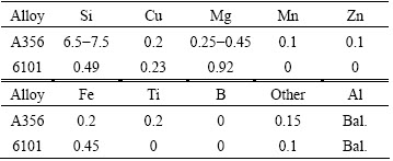
The 6101 aluminum alloy inserts were cut into bars with the dimensions of 60 mm �� 10 mm �� 2.5 mm, and the surfaces were polished with abrasive paper, then subjected to a series of chemical treatment procedures including degreasing, alkali erosion, acid pickling, the first zinc treatment, and the second zinc treatment. The main purpose of the surface treatment of the aluminum insert material was to remove the natural oxide layer from the surface and to simultaneously prevent the occurrence of reoxidation.
After chemical treatment, the 6101 aluminum alloy inserts were electro-plated in a zinc solution. After electro-plating, the 6101 aluminum alloy bars were pre-seated at the bottom of the mold, then A356 liquid metal was poured into the cylindrical mold (55 mm in diameter and 50 mm in height). The process is schematically presented in Fig. 1. The effect of thickness of the zinc layer, casting temperature and mold temperature on the interface formation between A356 aluminum alloy and 6101 aluminum alloy were evaluated, and it was found that with a 5 ��m thick zinc layer and carefully controlling of the overcastting parameters, good metallurgical bonding was formed in the joints.
2.2 Metallographic examination
To investigate the microstructure of the interface region, the samples were subjected to standard metallographic preparation including grinding and polishing. To observe the grain structure, the polished samples were further anodized at 30 V for 30 s in a 2% solution of fluoroboric acid. The anodized samples were then observed with optical microscope and scanning electron microscopy (SEM) equipped with energy dispersive spectroscopy (EDS) and electron back scattered diffraction (EBSD).
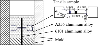
Fig. 1 Schematic illustration of mold and tensile sample
2.3 Mechanical testing
Tensile samples were prepared according to the GB/T228��2002 standard with sandwich structure (A356, interface region, 6101, interface region, A356) in the gauge section, which is shown schematically in Fig. 1. To ensure repeatability, at least three samples were tested in each testing condition. Micro-hardness of the samples was also measured across the joint interface region in the middle part of the bimetal at three different places.
3 Results and discussion
3.1 Coatings
The 6101 aluminum bars were received in rolled condition, which always leaves thick films containing oxides and lubricant remainders on the surface. An appropriate procedure was thus developed by combining several aluminum surface pre-treatments, including degreasing, alkali erosion, acid pickling, first zincate treatment, zinc retreatment and second zincate treatment. The lubricant containers, oxides and pickling layer were removed step by step. Then comes the most important step ��zincate process�� [22,23]. The use of this process has been widely reported for pre-treatments prior to electro-plating [24]. The process includes two parallel chemical reactions, the first is a etching process with the alkaline solution containing OH- anions, which removes Al2O3 (Eq. (1)). The second is a redox reaction, where Al oxides dissolve and Zn anions reduce and deposite on the aluminum matrix (Eqs. (2)-(5)).
Dissolution of oxide film:
Al2O3+2OH����2AlO2��+H2O (1)
Dissolution of aluminum:
Al+4OH����[Al(OH)4]��+3e (2)
[Al(OH)4]����AlO2��+2H2O (3)
Reduction of zinc:
[Zn(OH)4]2����Zn2++4OH�� (4)
Zn2++2e��Zn (5)
Total reaction of Reactions (2)-(5) is
2Al+3[Zn(OH)4]2����3Zn+2[Al(OH)4]��+4OH�� (6)
The result of the zincate treatment is a zinc layer with the thickness of 300-500 nm, because the deposition stops as soon as the surface is completely covered with zinc and ion-exchange reaction has no driving force anymore [10]. However, this zinc coating alone is insufficient, problems arise during experiments, the thin zinc layer evaporates and reoxidation of the aluminum insert occurs. Electro-plating method was thus introduced to increase the thickness of the zinc layer. The desired thickness is adjusted by controlling the coating time.
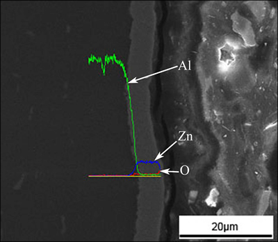
Fig. 2 SEM micrograph of 6101 aluminum alloy surface electro-plating with a layer of 5 um zinc coating, overlapped with element content variation of zinc, aluminum and oxygen
Figure 2 shows a SEM micrograph of the 6101 aluminum bar surface electro-plated with a layer of about 5 ��m thick zinc coating, overlapped with the element content variations of zinc, aluminum and oxygen at the joint interface between zinc coating and 6101 aluminum alloy. It can be seen that the zinc layer is uniform and remains constant over the entire surface. There is no aggregation of oxygen element. The transition of the zinc and aluminum alloy elements is very smooth.
3.2 Microstructure of overcast joints
The microstructure of the 6101 aluminum alloy- A356 aluminum alloy overcast joint is schematically presented in Fig. 3. The SEM micrograph of the interface region along with the corresponding concentration map of elements Si, O and Zn is presented in Fig. 4. It can be observed that along the interface, there is no aggregation of element O or Zn, and no defects or discontinuities are detected. In A356 aluminum alloy, the microstructure shows typical casting aluminum structure consisting of dendritic ��(Al) phase and uniformly dispersed eutectic silicon particles. In 6101 aluminum alloy, the microstructure shows typical wrought aluminum alloy structure consisting of fine grains. Between A356 aluminum alloy and 6101 aluminum alloy, there is a 100 ��m thick transition zone, and the microstructure shows fine equiaxed grained structure with eutectic silicon along the grain boundaries.
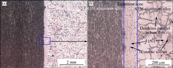
Fig. 3 Microstructures of A356 aluminum alloy and 6101 aluminum alloy overcast joint
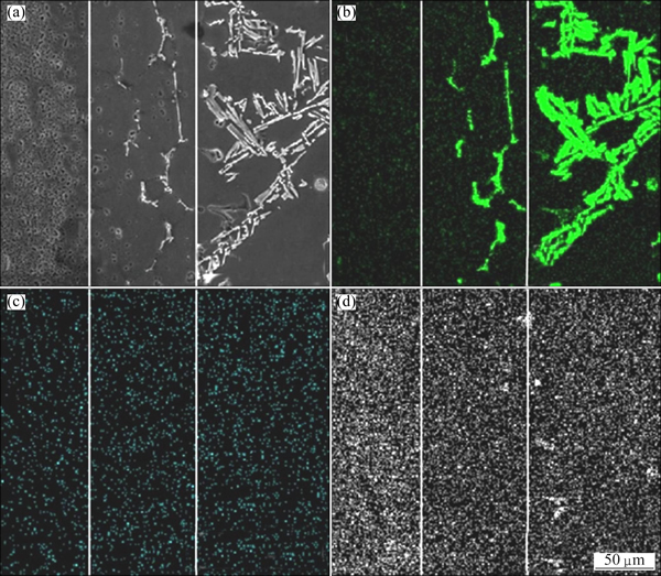
Fig. 4 SEM micrograph (a) of interfacial region and corresponding concentration maps of elements Si (b), Zn (c) and O (d)
In order to better understand the bonding process and bonding mechanism, the microstructural characteristics were investigated further by EBSD. Figure 5 depicts the inverse pole figure (IPF) map of interface region, 6101 aluminum alloy side and transition zone, along with pole figure (PF) of 6101 aluminum alloy side and transition zone. At least 100 grains were picked for each area. It can be seen that 6101 aluminum alloy side shows strong preference towards <001> orientations because of the rolling. The maximum texture intensity is 7.522. While the texture in transition zone exhibits a significant heterogeneity with the maximum texture intensity of 4.492. In can be inferred that the transition zone is received in as-cast state, i.e., the transition zone is formed during the solidification process after the partially melting of 6101 aluminum alloy. Based on the obtained microstructures and the discussion above, it can be inferred that there are four stages in the process of the overcastting and solidification, which is schematically presented in Fig. 6:
1) Casting of the A356 aluminum molten metal;
2) Melting of the zinc layer and locally melting of the surface region of 6101 aluminum insert;
3) Formation of the transition zone;
4) Solidification of the A356 aluminum melt.
Locally melting is the key factor for the formation of a good metallurgical bonding, which is decided by the temperature field in the system, especially the temperature field of the surface region of the 6101 aluminum insert. When the temperature of the surface region of 6101 aluminum insert is low, locally melting, even the melting of zinc layer could not be achieved. Mechanical bonding, rather than metallurgical bonding, with poor mechanical properties would form between the two aluminum alloys. When the temperature is high, the 6101 aluminum insert would severely melt that could not serve as insert material with high strength and excellent thermal and electrical conductivity. So, it is of great importance to carefully control the overcasting process.
During the solidification process, it is considered that the 6101 aluminum alloy serves as the heterogeneous nucleation substrate for the primary ��(Al) phase [13]. Undercooling was developed in the molten metal around the 6101 insert material. ��(Al) dendrites start to grow from the interface towards the A356 aluminum side, which is parallel to heat flow but in the opposite direction. The total undercooling can be written in mathematical ways as follows [25]:
��T=��Tt+��Tc+��Tr=��Tt+Kc��v+Kr/�� (7)
where ��Tt, ��Tc and ��Tr are thermal, constitutional and curvature undercooling, respectively, �� is the lamellar spacing, v is the growth rate, Kc and Kr are constants. In this instance, the non-preheated 6101 insert material chills the molten metal around it [16], besides, the partially melting of the 6101 insert material also absorbs the latent heat of fusion from the molten metal [15,16]. Therefore, a high thermal undercooling develops in the melt, which is of the most important contribution to the total undercooling. Apart from thermal undercooling, constitutional undercooling also needs to be taken into account. During solidification, the dissolved Si is rejected into the melt by growing phase. Because of this solute accumulation, the composition at the interface departs from the average composition, therefore, the change in local temperature occurs at the interface and thus constitutional undercooling develops in the melt [26]. A high total undercooling thus develops in the melt which results in the formation of the fine equiaxed grained structure in the transition zone.

Fig. 5 Inverse pole figure (IPF) maps of interface region (a), 6101 side (b) and transition zone (c) and pole figures (PF) of 6101 side (d) and transition zone (e)
Because of the partially melting of the 6101 insert material and the interdiffusion effect, a local transition from the composition of A356 aluminum alloy to 6101 aluminum alloy was developed. Figure 7 shows the solute distribution of the elements Si and Mg in the interface region of the overcast joints. The results indicate that the content of Si element decreases gradually across the interface from A356 side to 6101 side, while the content of Mg element increases gradually. Because of the high content of Si in the A356 matrix, Mg element barely solutes into the ��(Al) matrix but exists in the form of Mg2Si [27], so the content of Mg could not be detected at A356 side away from the interface.
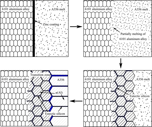
Fig. 6 Schematic drawing of four stages in process of overcasting and solidification
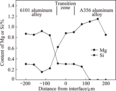
Fig. 7 Distribution of Mg and Si elements at overcast joint
3.3 Mechanical properties
Vickers microhardness was measured across the interface of the 6101 aluminum alloy-A356 aluminum alloy overcast joint. The Vickers microhardness of 6101 aluminum alloy, the transition zone and A356 aluminum alloy are in the range of HV 55-65, HV 65-75 and HV 70-80 respectively, as presented in Fig. 8. The hardness of A356 aluminum alloy is higher compared to that of 6101 aluminum alloy because there are more solute atoms dissolved in the ��(Al) phase. And because of the interdiffusion of solute atoms between A356 aluminum alloy and 6101 aluminum alloy [12], the hardness in transition zone is higher than that of 6101 aluminum alloy but lower than that of A356 aluminum alloy.
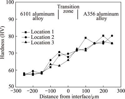
Fig. 8 Microhardness profiles measured in overcast 6101- A356 joint
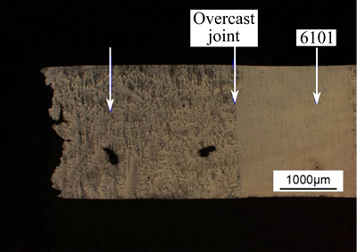
Fig. 9 Cross section view of tensile fractured specimen with overcast joint

Fig. 10 Comparison of tensile strengths of A356 aluminum alloy, bimetal and 6101 aluminum alloy
Figure 9 shows the cross section view of the tensile fractured specimen. Figure 10 shows the comparison of the tensile strength of A356 aluminum alloy, bimetal and 6101 aluminum alloy. It can be seen that final tensile fracture occurs in the as-cast A356 aluminum alloy side with an ultimate tensile strength (UTS) of 145 MPa, indicating that strength of the overcast joint area is higher than that of as-cast A356. The strength of overcast joint is higher than that of A356 aluminum alloy for two reasons. Firstly, the structure is more compact in transition zone than that in A356 aluminum alloy as discussed above. Secondly, the transition zone is solid solution strengthened because of the interdiffusion effect [12]. Figure 11 shows the SEM images of tensile fracture surfaces for A356 aluminum alloy, bimetal and 6101 aluminum alloy. It can be clearly observed that for A356 aluminum alloy and bimetal, the fracture occurs in an intergranular manner and shows obvious cleavage fracture characteristics. While for 6101 aluminum alloy, the fracture occurs in a transgranular manner and shows obvious dimple fracture. LLOYD et al [28] reported that the failure of AA3003/AA6111 clad materials during tensile process always takes place in the AA3003 component with lower tensile strength because during the tensile test, failure would take place in the AA3003 side when its UTS is reached. In this instance, during the tensile test, the fracture would nucleate in the inherent defects or the eutectic phase in the A356 aluminum alloy side, and the failure occurs when the UTS is reached, while the transition zone and 6101 aluminum alloy side remains good. It can be concluded that tensile fracture will be located in material with lower tensile strength if metallurgical bonding with high strength is formed between the two aluminum alloys.
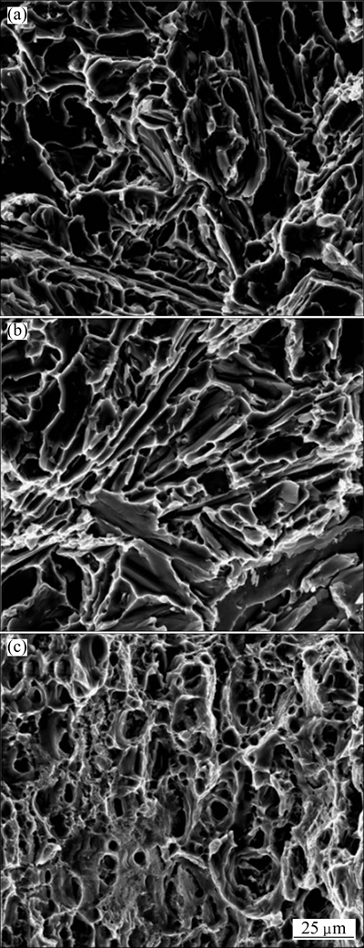
Fig. 11 SEM images of tensile fracture surface of A356 aluminum alloy (a), bimetal (b) and 6101 aluminum alloy (c)
According to the results of microstructure observation and mechanical testing, it is considered that an excellent metallurgical bonding can be achieved between A356 aluminum alloy and 6101 aluminum alloy by electro-plating a layer of zinc coating on the solid aluminum insert. The bonding pattern is a combination of fusion bonding and diffusion bonding.
4 Conclusions
1) Sound overcast joint between A356 aluminum alloy and 6101 aluminum alloy can be successfully fabricated by electro-plating a layer of Zn coating on the solid aluminum and carefully controlling overcasting process.
2) There is a transition zone between the two bonded aluminum alloys, the fine equiaxed grained structure in the transition zone is due to the high undercooling during solidification.
3) A local transition from the composition of A356 aluminum alloy to 6101 aluminum alloy is developed because of the partially melting of the 6101 insert material and the interdiffusion effect.
4) During the tensile test, the fracture occurs in the A356 aluminum alloy, indicating that the strength of the overcast joint is higher than that of as-cast A356 aluminum alloy (145 MPa).
References
[1] ZHAO Jia-lei, JIE Jin-chuan, CHEN Fei, LI Hang, CAO Zhi-qiang. Effect of immersion Ni plating on interface microstructure and mechanical properties of Al/Cu bimetal [J]. Transactions of Nonferrous Metals Society of China, 2014, 24(6): 1659-1665.
[2] LLOYD D J. Recent developments in controlling the architecture for property optimization in Al-based materials [J]. Scripta Materialia, 2013, 68(1): 13-16.
[3] LEE S, LEE M G, LEE S P, LEE G A, KIM Y B, LEE J S, BAE D S. Effect of bonding interface on delamination behavior of drawn Cu/Al bar clad material [J]. Transactions of Nonferrous Metals Society of China, 2012, 22(S3): s645-s649.
[4] LEE K S, LEE S E, KWON Y N. Interface characterization of Al/Cu 2-ply composites under various loading conditions [J]. Transactions of Nonferrous Metals Society of China, 2014, 24(S1): s36-s41.
[5] CHUANG T H, YEH M S, TSAO L C, TSAL T C, WU C S. Development of a low-melting-point filler metal for brazing aluminum alloys [J]. Metallurgical and Materials Transactions A, 2000, 31(9): 2239-2245.
[6] FEHIM F. Recent developments in explosive welding [J]. Materials and Design, 2011, 32(3): 1081-1093.
[7] LE H R, SUTCLIFFE M P F, WANG P Z, BURSTEIN G T. Surface oxide fracture in cold aluminium rolling [J]. Acta Materialia, 2004, 52(4): 911-920.
[8] LEE Y S, KIM W K, JO D A, LIM C Y, KIM H W. Recrystallization behavior of cold rolled Al-Zn-Mg-Cu fabricated by twin roll casting [J]. Transactions of Nonferrous Metals Society of China, 2014, 24(7): 2226-2231.
[9] PAPIS K J M, HALLSTEDT B,  J F, UGGOWITZER P J. Interface formation in aluminium-aluminium compound casting [J]. Acta Materialia, 2008, 56(13): 3036-3043.
[10]  C, SINGER R F. Aluminium�Caluminium compound fabrication by high pressure die casting [J]. Materials Science and Engineering A, 2011, 528(22-23): 7024-7029.
[11] XU G C, LUO A A, CHEN Y Q, SACHDEV A K. Interfacial phenomena in magnesium/aluminum bi-metallic castings [J]. Materials Science and Engineering A, 2014, 595: 154-158.
[12] SUN J B, SONG X Y, WANG T M, YU Y S, SUN M, CAO Z Q, LI T J. The microstructure and property of Al-Si alloy and Al-Mn alloy bimetal prepared by continuous casting [J]. Materials Letters, 2012, 67: 21-23.
[13] FU Y, JIE J C, LI W, PARK J, SUN J B, KIM J, LI T J. Microstructure and mechanical properties of Al-1Mn and Al-10Si alloy circular clad ingot prepared by direct chill casting [J]. Materials Science and Engineering A, 2013, 561: 239-244.
[14] DURRANT G, GALLERNEAULT M, CANTOR B. Squeeze cast aluminium reinforced with mild steel inserts [J]. Journal of Materials Science, 1996, 31(3): 589-602.
[15] LIU H W, GUO C, CHENG Y, LIU X F, SHAO G J. Interfacial strength and structure of stainless steel�Csemi-solid aluminum alloy clad metal [J]. Materials Letters, 2006, 60(2): 180-184.
[16] TANAKA Y, KAJIHARA M, WATANABE Y. Growth behavior of compound layers during reactive diffusion between solid Cu and liquid Al [J]. Materials Science and Engineering A, 2007, 445: 355-363.
[17] DIVANDARI M, VAHID GOLPAYEGANI A R. Study of Al/Cu rich phases formed in A356 alloy by inserting Cu wire in pattern in LFC process [J]. Materials and Design, 2009, 30(8): 3279-3285.
[18] XIONG B, CAI C, LU B. Effect of volume ratio of liquid to solid on the interfacial microstructure and mechanical properties of high chromium cast iron and medium carbon steel bimetal [J]. Journal of Alloys and Compounds, 2011, 509(23): 6700-6704.
[19] XIONG B W, CAI C C, WAN H, LU B P. Fabrication of high chromium cast iron and medium carbon steel bimetal by liquid�Csolid casting in electromagnetic induction field [J]. Materials and Design, 2011, 32(5): 2978-2982.
[20] BAE J H, PRASADA RAO A K, KIM K H, KIM N J. Cladding of Mg alloy with Al by twin-roll casting [J]. Scripta Materialia, 2011, 64(9): 836-839.
[21]  A. An investigation into stainless-steel/structural-alloy-steel bimetal produced by shell mould casting [J]. Materials and Design, 2009, 30(2): 264-270.
[22] SAITO M, MAEGAWA T, HOMMA T. Electrochemical analysis of zincate treatments for Al and Al alloy films [J]. Electrochimica Acta, 2005, 51(5): 1017-1020.
[23] QI G, CHEN X, SHAO Z. Influence of bath chemistry on zincate morphology on aluminum bond pad [J]. Thin Solid Films, 2002, 406(1-2): 204-209.
[24] QI G, FOKKINK L G J, CHEW K H. Zincating morphology of aluminum bond pad: Its influence on quality of electroless nickel bumping [J]. Thin Solid Films, 2002, 406(1-2): 219-223.
[25] KURZ W, FISHER D J. Fundamentals of solidification [M]. 4th ed. Zuerich: Trans Tech, 1998: 69.
[26] HEJAZI M M, DIVANDARI M, TAGHADDOS E. Effect of copper insert on the microstructure of gray iron produced via lost foam casting [J]. Materials and Design, 2009, 30(4): 1085-1092.
[27] GUPTA A K, LLOYD D J, COURT S A. Precipitation hardening in Al-Mg-Si alloys with and without excess Si [J]. Materials Science and Engineering A, 2001, 316(1-2): 11-17.
[28] LLOYD D J, GALLERNEAULT M, WAGSTAFF R B. The deformation of clad aluminum sheet produced by direct chill casting [J]. Metallurgical and Materials Transactions A, 2010, 41(8): 2093-2103.
�� ��1,2��������1,2���� ƽ1,2���ᄚ��1,2�������1,2��������3
1. �Ϻ���ͨ��ѧ ��Ͻ���ҹ������ģ��Ϻ� 200240��
2. �Ϻ���ͨ��ѧ ���������ϲ��Ϲ����ص�ʵ���ң��Ϻ� 200240��
3. General Motors Global Powertrain Engineering, 823 Joslyn Avenue, Pontiac, MI 48340-2920, USA
ժ Ҫ��ͨ����������ķ�����Һ̬A356���Ͻ����̬6101���Ͻ�������һ���о����Ͻ�ͷ������֯��Ԫ�طֲ���Ӳ�ȼ��������ܣ�������������γɻ����Ͷ�����Ϊ�����������ͨ���ڹ�̬6101���Ͻ������п�ķ�������ȷ����ʵ������������£�����ʹA356���Ͻ��6101���Ͻ�֮���γ�ұ���ϡ���2�����Ͻ�֮����γɹ����������ڹ�̬6101���Ͻ��������ĸ߹���ȣ������������ܵĵ��ᾧ��֯�����������ܲ����У�����λ��������A356��̬�Ͻ��ڲ���˵����ͷ����ǿ�ȸ���A356��̬�Ͻ��ǿ��(145 MPa)��
�ؼ��ʣ����Ͻ𣻸������죻���棻����֯����ѧ����
(Edited by Yun-bin HE)
Foundation item: Project supported by the General Motors Company in Pontiac, USA
Corresponding author: Qu-dong WANG; Tel: +86-21-54742715; E-mail: wangqudong@sjtu.edu.cn
DOI: 10.1016/S1003-6326(15)63699-8

