Trans. Nonferrous Met. Soc. China 23(2013) 3392-3399
Analysis and FEM simulation of extrusion process of bimetal tubes through rotating conical dies
H. HAGHIGHAT, M M. MAHDAVI
Mechanical Engineering Department, Razi University, Kermanshah, Iran
Received 7 January 2013; accepted 19 March 2013
Abstract: Bimetal tube extrusion process through rotating conical dies was studied analytically and numerically. A kinematically admissible velocity field was developed to evaluate the internal power and the power dissipated on frictional and velocity discontinuity surfaces. By balancing the moment applied by the rotary die with the moments caused by the circumferential frictions in the container and on the mandrel, the twisting length of the material in the container was determined. By equating the total power with the required external power, the extrusion pressure was determined by optimizing with respect to the slippage parameter between the die and the outer material. It is shown that the extrusion pressure is decreased by about 20% by the die rotation. The bimetal tube extrusion process through rotating die was also simulated using the finite element code, ABAQUS. Analytical results were compared with the results given by the finite element method. These comparisons show a good agreement.
Key words: bimetal tube; extrusion; rotating die; upper bound method; FEM
1 Introduction
Bimetals make possibility of combining properties of dissimilar metals. Bimetal tubes have useful applications in various industries where service conditions demand different requirements in the core of tube from those on its outside surface. Extrusion is a suitable process for manufacturing of bimetal tubes [1,2]. In this process, like other metal forming processes, estimation and minimization of the extrusion pressure is important. Due to the decrease in extrusion pressure, die life can be improved and it is possible to use a press of relatively low capacity.
Using of rotating dies in metal forming processes was firstly introduced by GREENWOOD and THOMPSON [3]. Compared with traditional forming processes, introducing die rotation reduces primary forming loads and improves the homogeneity of deformation [4]. KEMIN et al [5] showed that rotational upsetting provides homogeneous deformation and reduction in forming load by the finite element method. KIM et al [6,7] showed that the forging process which is performed by rotation can change the harmful effect of friction into a beneficial effect and also it can reduce forming load. BROVMAN [8] obtained an analytical solution based on stress analysis for material flow through a rotating conical die excluding the circumferential slipping effect. KIM and PARK [9] studied the backward extrusion process with low die rotation to improve the problems of conventional backward extrusion process: the requirement of large forming machine, the difficulty in selecting the die material caused by high surface pressure, high cost of forming machine caused by improvement of noise and vibration, etc. They were used in upper bound technique and FEM simulation. The results showed that the backward extrusion with die rotation is a very useful process because this process yields the homogeneous deformations and lower forming load. MA et al [10,11] analyzed the process of forward rod extrusion through steadily rotating conical dies theoretically and experimentally. They provided required torque for rotating the die from an external source and also supposed that the angular velocity of the material inside the die changes with power relation with radius of each position in proportion to virtual apex of the conic of the die. They inspected the effect of slippage factor and semi die angle in extrusion pressure and finally determined the optimum die angle.
Regarding to the extrusion of bimetal tubes, ALCARAZ and SEVILLAANO [12] tried to obtain stress and strain contours during high temperature extrusion process of bimetal tubes using a FE code. A fracture condition during the hot extrusion of bimetal tubes obtained by ALCARAZ et al [13] utilizing the upper bound method in combination with the minimum energy principle. CHITKARA and ALEEM [1,14] studied the mechanics of extrusion of axi-symmetric bimetallic tubes from solid circular billets using fixed mandrel with application of generalized upper bound and slab method of analyses. They investigated the effect of different parameters such as extrusion ratio, frictional conditions, shape of the dies and that of the mandrels on the extrusion pressures. HAGHIGHAT and ASGARI [2] proposed a generalized velocity field for bimetal tube extrusion process through curved dies with no rotation.
In this study, a velocity field for flow of a bimetal tube during extrusion through a rotating conical die is developed and it is used in upper bound model. Based on this model, the optimum die angle and the extrusion pressure are derived. The FEM simulation on the extrusion of a bimetal tube composed of aluminium as outer layer and copper as inner layer is also conducted.
2 Geometric descriptions of extrusion process
The rotational bimetal tube extrusion process consists of an axial movement of the punch and the rotational movement of the die. Schematic diagram of this process is shown in Fig. 1. An initially hollow billet, made up of two separate annular tubes of two different ductile materials, is considered. As shown in this figure, a moving cylindrical shaped mandrel with radius Rm is attached to the punch.
The material under deformation in the die and inside the container is divided to eight deformation zones, I-VIII as shown in Fig. 1, and they are used in upper bound analysis. A spherical coordinate system (r, ��, ��) is used to describe the velocity in zones I and II. The origin of spherical coordinate system is located at point O. The material inside the container along the total length L is divided into two segments. Within the length l, the material is twisted plastically inside the container and the region enclosed is denoted as zone III. A cylindrical coordinate system (r, ��, y) is used to describe the velocity field in the deformation zone III where the axial coordinate y is parallel to the extruding direction. The billet in the remaining length (L-l) is designated by zones V and VI. In these zones, the incoming material is assumed to flow horizontally as a rigid body with a velocity vi. In zones VII and VIII, the extruded material is assumed to flow horizontally as a rigid body with an axial velocity vf. Zones I and II are the deformation zones. Zone I is separated from zone III by a surface of velocity discontinuity S1. Zone I is separated from zone VII by a surface of velocity discontinuity S2. The mathematical equations for radial positions of surfaces S1 and S2 of velocity discontinuity are given by
 ,
,  (1)
(1)
where �� is the semi-angle of conical die.
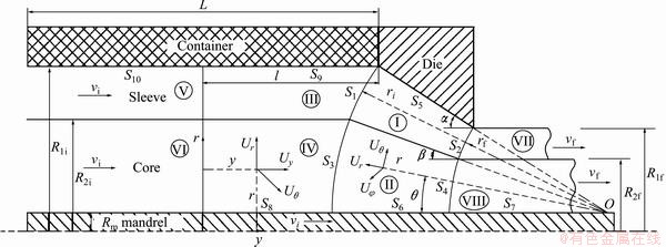
Fig. 1 Schematic diagram of bimetal tube extrusion process through rotating conical die, geometric parameters and its deformation zones
2.1 Velocity fields and power terms for deformation zones I and II
The first step in modelling and analyzing a metal forming process by use of upper bound approach is to select a suitable velocity field for the material which is deforming plastically.
For deformation zones I and II, the same rotational component of velocity field,  which was employed by MA et al [11] to analyze mono-metal rod extrusion process through rotating conical dies, is extended here for bimetal tube extrusion process through rotating conical dies. The two other velocity components,
  and
and  , are assumed similar to the velocity field proposed by EBRAHIMI et al [15] for mono-metal tube extrusion. So, the total velocity field for tube extrusion process through rotating conical dies is described by
 (2)
(2)
 (3)
(3)
 (4)
(4)
where ��d is the angular velocity of the die, and ��1 is the circumferential slippage parameter defined as the angular velocity ratio of material at exit of conical die to rotating die. Slippage parameter ��1 varies between 0 and 1, where the value of 1 implies that the extruded tube rotates at the same angular velocity as that of the die. The optimal value of ��1 can be determined by minimizing the extrusion pressure. The velocity vf is the speed of the extruded tube and from the volume flow balance, we have
 (5)
(5)
where vi is the axial speed of the tube in the entrance of the die.
When the mandrel radius goes to zero, Eqs. (2) to (4) reduce to the velocity field proposed by MA et al [11] for forward rod extrusion through rotating conical dies.
The strain rates in spherical coordinates are defined as


 (6)
(6)
where  (with i=j) is a shear strain rate component.
With the strain rate tensor and the velocity field, the standard upper bound method can be implemented. This method involves calculating the internal power of deformation over the deformation zones volume, the shear power losses over two surfaces of velocity discontinuity and the frictional power losses between the material and the tooling.
The internal power dissipated in the deformation zone is given by
 (7)
(7)
For deformation zone I that is surrounded by two velocity discontinuity surfaces of S1 and S2, interface surface as well as the die surface, the differential volume is
 (8)
(8)
Substituting the strain rate tensor from Eq. (6), and the differential volume from Eq. (8) into Eq. (7), the internal power of deformation in zone I becomes

 (9)
(9)
where ��s is the mean flow stress of sleeve material and it is determined by
 (10)
(10)
The internal power of deformation in zone II that is surrounded by two velocity discontinuity surfaces, S3 and S4, interface surface as well as the mandrel surface, is calculated as

 (11)
(11)
where ��c is the mean flow stress of core material and it is given by
 (12)
(12)
and �� is the angular position of the interface surface between core and sleeve material in the deformation zone and is given by
 (13)
(13)
The general equation for the power losses along a shear surface of velocity discontinuity in an upper bound model is
 (14)
(14)
where for velocity discontinuity surfaces S1 and S3, there are
 ,
,  (15)
(15)
For velocity discontinuity surfaces S2 and S4, there are
 ,
,  (16)
(16)
Inserting Eqs. (15) and (16) into Eq. (14), the power values dissipated on the velocity discontinuity surfaces S1, S2, S3 and S4 are determined respectively as
 (17)
(17)
 (18)
(18)
 (19)
(19)
 (20)
(20)
The general equation for the frictional power losses along a surface with a constant friction factor m is
 (21)
(21)
For the conical surface of the die, frictional surface S5, the magnitude of the velocity difference and the differential surface are

 (22)
(22)
where
 (23)
(23)

 (24)
(24)
Replacing Eqs. (23) and (24) into Eq. (22) and then inserting into Eq. (21) gives the frictional power losses along the conical surface of the die as

 (25)
(25)
where md is the constant friction factor between the sleeve material and the die.
For frictional surface S6, there are

 (26)
(26)
where
 (27)
(27)
and
 (28)
(28)
The frictional power losses along frictional surface S6 can be determined by

 (29)
(29)
where mm is the constant friction factor between the material and the mandrel.
For frictional surface S7, there are
 ,
,  (30)
(30)
The frictional power losses along surface S7 can be given by
 (31)
(31)
2.2 Velocity fields and power terms for deformation zones III and IV
For deformation zones III and IV, using the cylindrical coordinate system (r, ��, y) in Fig. 1, the same components of velocity field which were employed by MA et al [11] to analyze mono-metal rod extrusion process through rotating conical dies are used for bimetal tube extrusion process through rotating conical dies as
 ,
,  ,
, 
where  (32)
(32)
The strain rate for the deformed tube in container can be given as
 (33)
(33)
Replacing Eq. (33) into Eq. (7) and noting that  the internal power of deformation in zone III is determined as

 (34)
(34)
The internal power of deformation in zone IV is determined as

 (35)
(35)
The powers dissipated on the frictional surfaces S8��S10 are also can be obtained by Eq. (21). For frictional surface S8, there are
 ,
,  (36)
(36)
The frictional power losses along the surface S8 can be given by

 (37)
(37)
The velocity discontinuity on surface S9 becomes
 (38)
(38)
The frictional power losses along surface S9 can be given by

 (39)
(39)
where

 (40)
(40)
where mc is the constant friction factor between the material and the container.
Finally, for frictional surface S10, there is
 (41)
(41)
where L is the length of tube in the container and ��ys is flow stress of sleeve material before any deformation.
In the present work, the bonding condition between the core and the sleeve is assumed to be sticky and there is no slippage between core and sleeve materials and therefore the frictional power losses along interface surfaces are zero.
2.3 Twist moments
In addition to the power applied by the punch, a twist moment Md is supplied by the rotating die and this moment can be calculated as

 (42)
(42)
As the balance among twisting moments must be maintained, the moment applied by the rotary die is balanced with summing up the moments caused by the circumferential frictions in the container and on the mandrel.
The twist moment within the container is given as
 ,
,  (43)
(43)
The twist moments generate in the mandrel surfaces, and S6, S7 and S8 can be derived from

 (44)
(44)

 (45)
(45)
 ,
,  (46)
(46)
The balance of the couples gives
 (47)
(47)
The twisting length l can be determined by satisfying above equation with a given ��1.
2.4 Extrusion pressure
Based on the upper bound model, the total power needed for a bimetal tube extrusion process can be obtained by summing the internal powers and the powers dissipated on all frictional and velocity discontinuity surfaces

 (48)
(48)
The total external power is given by
 (49)
(49)
Therefore, the total upper bound solution for relative extrusion pressure is given by
 (50)
(50)
3 Results and discussion
The analytical model discussed in the previous section is aimed at predicting the relative extrusion pressure. A MATLAB program is implemented for the previously derived equations. All integrals that are presented in the power terms are evaluated by numerical integration. The average pressure required for bimetal tube extrusion becomes a function of the process parameters (geometric parameters of initial and extruded bimetal tube, friction factor, semi-die die angle and angular velocity of die) and the slippage parameter ��1 associated with the velocity field. Equation (50) is solved by a numerical integration method. The solution is optimized with respect to the slippage parameter. Thus, the lowest upper bound value of the relative extrusion pressure and the semi-die angle with the minimum pressure are obtained.
To make a comparison with the developed model, the bimetal tube extrusion process was simulated using the finite element code, ABAQUS. A bimetal tube composed of aluminium as outer layer and copper as inner layer was used. The configuration of the outer and inner layers is shown in Fig. 2. The flow stresses for copper and aluminium at room temperature are obtained as [16]

 (51)
(51)
A three-dimensional model was used for FEM analyses. The billet model was meshed with C3D8R elements. Punch, mandrel, container and die are assumed as rigid bodies, since they are not meshed. However, sufficiently fine meshing is essential in material, which undergoes plastic deformation. The die model is able to rotate along its axis of symmetry and the punch model is loaded by specifying displacement in the axial direction. Also, container model is fixed by applying displacement constraint on its nodes. Figure 3(a) illustrates the mesh used to analyze the deformation in extrusion of bimetal tube with configuration shown in Fig. 2, through a conical die with ��=20�� and ��=0.5 rad/s. Deformed model of the bimetal tube is shown in Fig. 3(b). As it is expected, the material is twisted not only in the die but also inside the container as mentioned in Section 2.
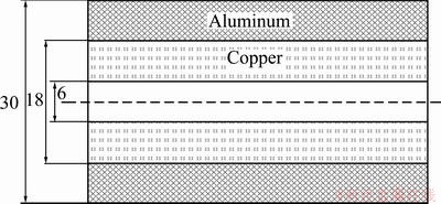
Fig. 2 Configuration of bimetal tube before extrusion (unit: mm)
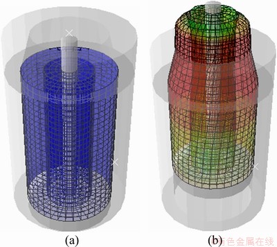
Fig. 3 Finite element mesh (a) and deformed mesh tube (b) in extrusion process through rotating conical die
In Fig. 4, the relative extrusion pressures for different angular velocities of the die, obtained from the upper bound solution, are compared with the FEM simulation results. The results show a good agreement between the upper bound data and the FEM results.
This figure also shows that with increasing of the angular velocity of the die, the relative extrusion pressure is decreased but this reduction saturates at a high die angular velocity.
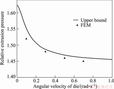
Fig. 4 Comparison of analytical relative extrusion pressures with FEM data for different angular velocities of die at ��=20��, md=0.4 and mc=0.2
In Fig. 5, the relative extrusion pressures for different semi-die angles obtained from the upper bound solution are compared with the FEM simulation results. The results show a good agreement between the upper bound data and the FEM results. As is expected, there is an optimum die angle in which the extrusion pressure is minimized.
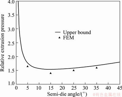
Fig. 5 Comparison of analytical relative extrusion pressures with FEM data for different semi-die angles at ��=0.1 rad/s, md=0.4 and mc=0.2
The effect of angular velocity on the relative extrusion pressure for different values of die friction factors is shown in Fig. 6. It is observed that the extrusion pressure is decreased by increasing the die angular velocity and decreasing the die friction factor, but this reduction saturates at a high die angular velocity. From this figure, it is seen that the relative extrusion pressure is decreased by about 20% by the die rotation for die friction factor 0.8.
The effect of die angle on the relative extrusion pressure for different values of die friction factors is shown in Fig. 7. As is expected, for a given value of die friction factor, there is an optimal die angle, which minimizes the extrusion pressure, and the optimum die angle increases when friction factor of die increases. This figure also shows that an increase in the friction factor of die tends to increase the extrusion pressure.
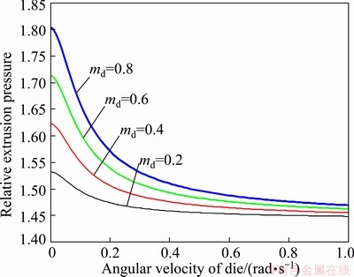
Fig. 6 Effect of angular velocity of die on relative extrusion pressure for different friction factor of die at mc=0.2
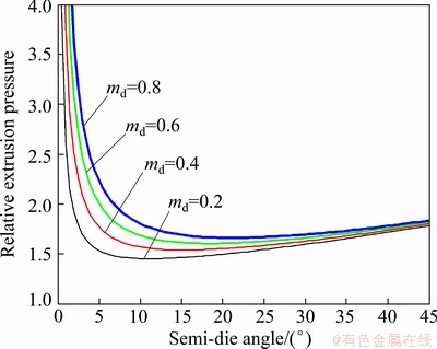
Fig. 7 Effect of semi-die angle on relative extrusion pressure for different friction factor of die at ��=0.1 rad/s and mc=0.2.
The effect of angular velocity on the relative extrusion pressure for different values of the tube entrance speed is shown in Fig. 8. It is observed that the extrusion pressure is decreased by decreasing the die angular velocity and decreasing the entrance speed, but this reduction is low at high entrance speeds.
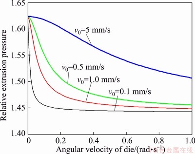
Fig. 8 Effect of angular velocity of die on reduction of extrusion pressure for different extruding speed at ��=20��, md=0.4 and mc=0.2
The effect of angular velocity of the die on twisting length of the material inside the container for different die friction factors is shown in Fig. 9. It is observed that for a given value of die friction factor, twisting length of the material inside the container decreases when the friction factor of die increases. This figure also shows that an increase in the friction factor of die tends to increase twisting length of the material inside the container.
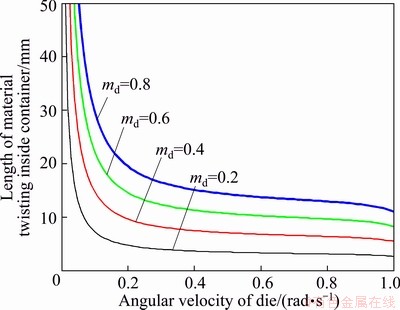
Fig. 9 Effect of angular velocity of die on twisting length of material inside container for different die friction factors at ��=20��, y0=1 mm/s and mc=0.2
4 Conclusions
An upper bound model for analysis of the tube extrusion process through rotating conical dies was developed. The results showed a good agreement between the analytical solution and FEM simulation. The developed upper bound solution can be very beneficial in studying the influence of multiple variables on the tube extrusion process through rotating conical die and for a given process parameters. It can be used for finding the optimum semi die angle which minimizes the extrusion pressure.
References
[1] CHITKARA N R, ALEEM A. Extrusion of axi-symmetric bi-metallic tubes: Some experiments using hollow billets and the application of a generalized slab method of analysis [J]. International Journal of Mechanical Sciences, 2001, 43: 2857�C2882.
[2] HAGHIGHAT H, ASGARI G R. A generalized spherical velocity field for bi-metallic tube extrusion through dies of any shape [J]. International Journal of Mechanical Sciences, 2011, 53: 248-253.
[3] GREENWOOD H, THOMPSON F C. Wires drawn through rotating dies [J]. Nature, 1931, 128: 152.
[4] MA X, BARNETT M. An upper bound analysis of forward extrusion through rotating dies [C]//Proceedings of the 8th ESAFORM Conference on Material Forming. Bucharest, Romania: Publishing House of the Romanian Academy, 2005: 565-568.
[5] KEMIN X, ZHEN W, YAN L. FEM analysis of cylinder twist-compression deformation regularity [J]. Journal of Materials Processing Technology, 1997, 69: 148-151.
[6] KIM Y H, PARK J H, JIN Y E. An upper bound analysis for torsional upset forging of cylindrical billets [C]//Proceedings of the Sixth International Conference on Technology of Plasticity. Nuremberg: Springer, 1999, 2: 859-864.
[7] KIM Y H, PARK J H, JIN Y E. Experimental investigation of the forming parameters of the rotational upset forging process [J]. Journal of Materials Processing Technology, 2001, 111: 103-106.
[8] BROVMAN M J. Steady forming processes of plastic materials with their rotation [J]. International Journal of Mechanical Sciences, 1987, 29: 483-489.
[9] KIM Y H, PARK J H. Upper bound analysis of torsional backward extrusion process [J]. Journal of Materials Processing Technology, 2003, 143-144: 735-740.
[10] MA X, BARNETT M R, KIM Y H. Forward extrusion through steadily rotating conical dies. Part I: Experiments [J]. International Journal of Mechanical Sciences, 2004, 46: 449-464.
[11] MA X, BARNETT M R, KIM Y H. Forward extrusion through steadily rotating conical dies. Part II: Theoretical analysis [J]. International Journal of Mechanical Sciences, 2004, 46: 465-489.
[12] ALCARAZ J L, SEVILLANO J G. An analysis of the extrusion of bimetallic tubes by numerical simulation [J]. International Journal of Mechanical Sciences, 1996, 38: 157-173.
[13] ALCARAZ J L, MARTINEZ-ESNAOLA J M, GILl-SEVILLANO J. An analytical approach to the stress field in the extrusion of bimetallic tubes [J]. International Journal of Solids and Structures, 1996, 33: 2075-2093.
[14] CHITKARA N R, ALEEM A. Extrusion of axi-symmetric bimetallic tubes from solid circular billets: Application of a generalized upper bound analysis and some experiments [J]. International Journal of Mechanical Sciences, 2001, 43: 2833-2856.
[15] EBRAHIMI R, REIHANIAN R, KANAANI M, MOSHKSAR M M. An upper-bound analysis of the tube extrusion process [J]. Journal of Materials Processing Technology, 2008, 184: 411-419.
[16] HWANG Y M, HWANG T F. An investigation into the plastic deformation behavior within a conical die during composite bar extrusion [J]. Journal of Materials Processing Technology, 2002, 12: 226-233.
˫��������ģ��ת��ѹ���̷���������Ԫģ��
H. HAGHIGHAT, M M. MAHDAVI
Mechanical Engineering Department, Razi University, Kermanshah, Iran
ժ Ҫ����˫��������ģ��ת��ѹ���̽��з�������ֵģ�⡣�������˶������ٶȳ������������������Լ���Ħ�����ٶȶ����ϵ���Ĺ���ͨ��ƽ����תģ������о������Ħ����������������ȷ�������в��ϵ����߳��ȡ�ͨ�����������������ƽ���ܹ������Ż�ģ�����ⲿ����֮����йػ��Ʋ������õ���ѹ�����������������ģ��ת��ѹ��ʹ��ѹ������20%������ABAQUS����Ԫ����ģ��˫�����ܵ���ת��ѹ���̡�ģ���������������ֳ��ܺõ�һ���ԡ�
�ؼ��ʣ�˫�����ܣ���ѹ��תģ�����ޣ�����Ԫ��
(Edited by Hua YANG)
Corresponding author: H. HAGHIGHAT; Tel: +98-831-4274530; Fax: +98-831-4274542; E-mail: hhaghighat@razi.ac.ir
DOI: 10.1016/S1003-6326(13)62879-4

