
High cycle fatigue properties of die-cast magnesium alloy AZ91D-1%MM
XU Yu-lei(������)1, ZHANG Kui(�� ��)1, LI Xing-gang(���˸�)1, LEI Jian(�� ��)2,
YANG Yuan-sheng(��Ժ��)3, LUO Tian-jiao(���콾)3
1. State Key Laboratory for Fabrication and Processing of Nonferrous Metals, General Research Institute for Non-ferrous Metals, Beijing 100088, China;
2. Dongfeng Motor Co., LTD Material Technology Institue of CVTC, Shiyan 442001, China;
3. Institute of Metal Research, Chinese Academy of Sciences, Shenyang 110016, China
Received 12 June 2008; accepted 5 September 2008
Abstract: The high cycle fatigue properties of the die-cast magnesium alloy AZ91D containing 1% mischmetal (mass fraction) at a fatigue ratio of 0.1 were investigated. The difference in the microstructure between the skin and core region of the die-cast magnesium alloy was analyzed by optical microscopy. The mechanical property tests indicate that the values of the tensile strength, elongation and hardness are 185 MPa, 1.5% and HBS 70��3 at room temperature, respectively. The p��S��N curve (p=50%) of the die-cast magnesium alloy AZ91D-1%MM is determined and the mean fatigue strength corresponding to 3.8��105 cycles is 70 MPa. A linear relation between S and Np in log scale between 103 and 106 cycles is written with a equation. The mechanical properties are influenced by the casting defects. The fatigue life of the samples with minor defects is near to the upper limit of the fatigue life data. The fatigue fracture surface of the samples with minor defects possesses the mixed characteristics of quasi-cleavage, lacerated ridge and dimple and it is brittle fracture mode as a whole.
Key words: magnesium alloy; die casting; high cycle fatigue; rare earths; fractography
1 Introduction
The increasing utilization of magnesium alloys in the auto industry would meet the need of reducing vehicle mass and increasing automotive fuel economy[1]. Most magnesium alloy components are produced by the high-pressure die casting. Two major magnesium alloy systems, including AZ91D and AM50, are available at moderate cost, and their mechanical properties are good under 100 ��. Today, the die-cast magnesium alloys are used in cars for low stress applications such as covers and less frequently for mechanically loaded structural components such as oil pans, air intake grills, and steering wheels. Under the environment bearing the low stress and circulate load, the fatigue fracture is the main failure mode of the die-cast magnesium, so it is necessary to study its high cycle fatigue properties.
The addition of mischmetal into the magnesium alloys can remarkably improve the mechanical properties[2-3]. It was recommended to add 1% MM
(mass fraction) to the AZ91D to get the best mechanical property[4-5]. The fatigue strength of the AZ91D with 1% Ce (mass fraction) addition evaluated by the up-and-down load method reached the best level[6]. Simple smooth-specimen laboratory fatigue data are very general and can be utilized in designing virtually any piece of hardware made of the specimen material. A plot of cyclic stress level versus the logarithm of life, called p��S��N curves, constitute design information of fundamental importance for machine parts subjected to repeated loading. The use of die-cast magnesium alloy was limited by the difficulty in finding out a mean S��N curve for practicing engineers concerned with the design and failure analysis of components subjected to repeated loading. In the present work, the die-cast test bars of the magnesium alloys AZ91D containing 1% MM were produced at usual temperature and high cycle fatigue properties at a fatigue ratio of 0.1 and ambient temperatures were investigated. The mean S��N curve and fracture surface were analyzed.
2 Experimental
The materials used in the study were a commercial AZ91D magnesium alloy and the mischmetal with nominal composition of 50% cerium, 30% lanthanum, 12% neodymium and 6% praseodymium (mass fraction).
The AZ91D was smelted in an electric resistance furnace under a protection of cover gas (0.3% SF6 and 99.7% CO2, volume fraction) and the mischmetal was added as Mg-25.07%MM (mass fraction) intermediate alloy, just as described in Ref.[7]. The melt was held at 680 �� for 10 min after it was refined by flux. Then the melt was injected into the mould, with a die temperature of 200 ��, in less than 100 ms at pressures that may be as high as 150 MPa at a cold chamber die casting machine (DCC630M) and a minimum of 20 good specimens were cast. The specimen mould designed according to GB/T 13822��92 has two tensile test bars but only the test bar inside the mould was used in our experiment (Fig.1)[8]. Some standard 6.4 mm test bars were tensile tested at SHIMADZU AG-50 kN material test machine at room temperature and some were machined into unnotched specimen to determine their high cycles fatigue properties at INSTRON8871 fatigue testing machine. The fatigue specimen with a gauge length of 50 mm, diameter of 6 mm was close to the shape of the tensile test bars but its surface roughness reached ��9.
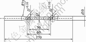
Fig.1 Geometrical dimensions of standard specimen[8] (used for tensile testing, D=6.4 mm; used for fatigue testing, D=6.0 mm)
The microstructure of the die-cast magnesium alloy was characterized by optical microscopy (Neophot-32). The chemical composition was measured by inductively- coupled plasma (ICP) spectroscopy with an accurate level of 0.01% as shown in Table 1. The fracture appearances were evaluated on the basis of fractographs by scanning electron microscopy (JSM-840) with an energy dispersive spectrometer (Oxford).
The specimens were also subjected to the hardness measurement. The Brinell hardness tests was obtained
Table 1 Chemical composition (mass fraction, %)
using a 2.5 mm-diameter steel ball at a load of 294 N applied for a period of 30 s.
3 Results and discussion
3.1 Microstructure of die-cast magnesium alloy AZ91D-1%MM
The die-cast magnesium alloy has unique microstructure feature. The casting process of this alloy produced a fine microstructure near the skin of the casting, and a core consisting of dendritic structures and bands of defects, such as porosity. The typical microstructures of the skin and the core regions are shown in Fig.2. The relative measurements of the grain size of the die-cast magnesium alloys AZ91D-1%MM were preformed using the random cord intercept method and summarized in Table 2. The average measured grain size of the precipitates from the skin region is 58��18 ��m, and that of the core region is 66��30 ��m. So the grain size of the precipitates in the skin is finer than that in the core. There are more cast pores in the core region. The average measured grain size of the Mg matrix from the skin region is 20��3 ��m, and that of the core region
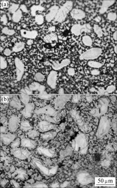
Fig.2 Microstructures of die-cast Mg alloy AZ91D-1%MM: (a) Skin region; (b) Core region
Table 2 Image analysis results for grain size (��m)

is 16��7 ��m. The grain size of the Mg matrix in the skin is coarser than that in the core. According to the results, the tensile behaviour of the die-cast magnesium alloy is predominately influenced by the outer fine-grained skin region[9]. So the skin region of the die-cast test bar is preserved during cylindrical fatigue specimens which are machined and longitudinal polished.
The XRD pattern of the die cast magnesium alloy AZ91D-1%MM is shown in Fig.3. Six distinct phases are identified in the patterns: Mg, Al12Mg17, AlCe, LaMg2, Al2Ce and Al2La. The peak positions for Mg, the major phase, are shifted to higher angles. This shift is consistent with dissolved Al and some RE elements in the phase. The role of the rare earth elements in the microstructure and mechanical properties control of the die-cast magnesium alloys include solid solution hardening, grain boundary hardening and dispersion hardening[10].
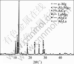
Fig.3 XRD pattern of die-cast AZ91D-1%MM
3.2 Hardness testing
Hardness in different positions of the die-cast sample is shown in Fig.4. The hardness was measured for five times along the die-cast sample from the sprue to the end and the average was recorded. It is obvious that the hardness is HBS 70��3 from the sprue to the middle of sample but decreases behind that position. This phenomenon is related to the shape of the sample, the parameters of the die casting process and the crystallization time of the metal melt. Because the diameter of gaugage section is small, and the middle section is solidified firstly. The melt near the sprue can still be solidified under pressure so its hardness can keep constant. But the melt far away from the sprue is solidified without pressure so its hardness decreases and many defects are made out.
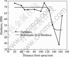
Fig.4 Hardness distribution for die-cast sample
3.3 Tensile properties at room temperature
The tensile properties from the die-cast magnesium AZ91D-1%MM was measured for three times using three samples and exhibited significant variability due to the presence of significant gas and shrink porosity. The mean values of the parameters are tensile strength of 185 MPa, yield strength of 159 MPa, and elongation ratio of 1.5%. The sample exhibiting the best tensile properties has tensile strength of 197 MPa, yield strength of 187 MPa and elongation of 1.5%.
3.4 Fatigue properties
The fatigue specimens were obtained from 16 die-cast tensile testing bars and tested at different stress levels. The fatigue data from these specimens were summarized. S��N curve constitute design information of fundamental importance for machine parts subjected to repeated loading. The S��N curve in the literatures generally refers to the mean curve unless otherwise specified. The S��N curve of the die-cast magnesium alloy AZ91D-1%MM (mass fraction) is shown in Fig.5. The ferrous alloys and titanium exhibit a steep branch in the relatively short life range, levelling off to approach a stress asymptote at longer lives. This stress asymptote is called the fatigue limit. The nonferrous alloys do not exhibit an asymptote, and the curve of stress versus life continues to drop off indefinitely. For those alloys there is no fatigue limit, and failure as a result of cyclic load is only a matter of applying enough cycles[11]. To characterize the failure response of nonferrous materials, the term fatigue strength at a specified life, ��N, was used. As shown at the mean S��N curve of Fig.5, mean fatigue strength at 3.8��105 cycles is 70 MPa. The fatigue lives of specimens are distributed over a much wider range for there are many casting defects in samples. Among samples tested at 70 MPa, some containing major defects fail within 104 cycles and some with minor defects do not fail at 107 cycles.
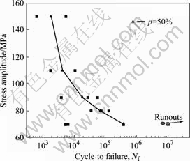
Fig.5 Fatigue life curve for die-cast Mg alloys AZ91D-1%MM
There is almost a linear relation between S and Np in log scale between 103 and 106 cycles with a coefficient of correlation (r) 0.950. It is expressed with the following equation[12]:
 (1)
(1)
where p= 50%, the coefficients ap=17.85 and bp=-6.83 can be obtained from experimental date by the least squares method. Thus the relation between S and Np is written as the following equation:
 (2)
(2)
In general, the entire fatigue process involves the nucleation and growth of a crack or cracks to final fracture. The multistage fatigue model developed by MCDOWELL et al[13-14] was applied to study the fatigue life of the die-cast magnesium alloys AZ91D-1%MM. The fractographic examination indicated three distinct stages of fatigue damage in the high cycle fatigue loading regime: crack incubation, microstructurally small crack growth and long crack growth. Cracks incubated almost exclusively at the cast defects or at large pores inside specimens. Microstructurally small cracks grew along the weak boundaries of the grains and dendrites or at very closely packed microstructural discontinuities. Long cracks grew in a transgranular fashion.
After the fatigue testing, the fatigue specimens were examined by SEM. The casting defects were categorized into two groups based upon the scanning electron micrographs of the fracture surface: minor defects and major defects [15]. The fatigue life data of the specimens classified by different extents of the defects are shown in Fig.6.
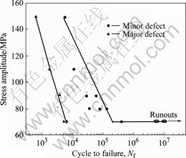
Fig.6 Fatigue life data for die-cast AZ91D-1%MM
Specimens with major defects fatigue failure (fracture) during limited exposures to cyclic loading but those with minor defects endure more cycles. The upper limit of the fatigue life shows abrupt change in slope called the knee point. The stress amplitude at the knee point is 70 MPa just like the fatigue limit since there is no sign of failure, even after the application of more than 107 stress cycles. In fact, it is difficult to reach a definite conclusion on the existence of fatigue limits for unnotched specimens of nonferrous metals[16]. MAYER et al[17] showed the existence of a fatigue limit in the die-cast magnesium alloys AZ91hp, AM60hp and AE42hp. The existence of a fatigue limit should be caused by the non-propagating fatigue cracks rather by a non-initiation condition. That is to say, the fatigue cracks may have initiated at porosity, however, the cyclic loading is too small to further propagate the crack when a certain length is reached. Assuming an extremely small pore size as the site of damage incubation, the upper bound for the die-cast specimens were estimated, just like the existence of a fatigue limit.
3.5 Fatigue fracture surface
Although the three stages of fatigue damage in the specimen with major defects were hardly distinguished because the crack incubated at much porosity and grew quickly, the fractographic examination to specimen with minor defects indicated those stages of fatigue damage in the high cycle fatigue loading regime: crack incubation, microstructurally small crack growth, and long crack growth. The fatigue fracture surfaces of specimen which failed after 1.2��105 cycles at a stress amplitude of 80 MPa are shown in Fig.7. The macroscopic appearance of the fracture surface in Fig.7(a) is straight and has no obvious plastic deformation. The micrographs at high magnification shown in Figs.7(b, c, and d) are taken within three areas in Fig.7(a). The fatigue crack initiated
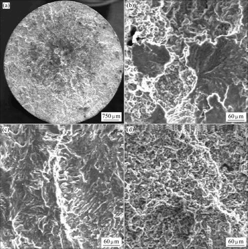
Fig.7 SEM images of fatigue fracture surface of specimen: (a) Overall fracture surface; (b) At crack incubation region; (c) At small crack growth region; (d) At long crack growth region
at casting defects is shown in Fig.7(b). There are the mixed-rupture characteristics of cleavage step, river shape, and minute tough dimple. In the hexagonal close-packed metals, such as magnesium, primary cleavage occurs on the (0001) basal plane. It is a typical brittle fracture feature[18]. The micrograph of microstructurally small crack growth shown in Fig.7(c) is composed of tearing ridge. It is a ductile fracture feature[18]. The micrograph of long crack growth is shown in Fig.7(d). It is straight and forms the semicircle dimple because of the shear stress. As a whole, the die-cast magnesium alloy AZ91D-1%MM shows the mixed ductile and brittle fracture feature.
The fatigue fracture surface of the specimen, which failed after 1.2��105 cycles at 80 MPa, is shown in Fig.8. It is an example of cracks initiated from porosity. Fatigue striations were produced to represent a velocity discontinuity where fracture propagation can hesitate in response to an abrupt change in magnitude of principal tension at the crack tip[19-20].
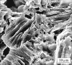
Fig.8 SEM image of fracture surface of specimen at crack incubation region
4 Conclusions
1) The microstructure between the skin and core region of the die-cast AZ91D-1%MM (mass fraction) was analyzed by optical microscopy. The grain size (20��3 ��m) of Mg matrix in the skin is coarser than that (16��7 ��m) in the core but the grain size (58��18 ��m) of precipitates in the skin is finer than that (66��30 ��m) in the core. There are more cast pores in the core region.
2) The values of the tensile strength, elongation and hardness of the die-cast AZ91D-1%MM are 185 MPa, 1.5% and HBS 70��3 at room temperature, respectively.
3) The p��S��N curve (p=50%) of the die-cast magnesium alloy AZ91D-1%MM is determined and the mean fatigue strength corresponding to 3.8��105 cycles is 70 MPa. A linear relation between S and Np in log scale between 103 and 106 cycles is written in the following equation: lgNp=17.85+6.83lgS. The fatigue life of the samples with minor defects is near the upper limit of fatigue life data.
4) The fatigue fracture surface of the samples with minor defect possesses the mixed characteristics of quasi-cleavage, lacerated ridge and dimple and it is a brittle fracture mode as a whole.
References
[1] FRIEDRICH H, SCHUMANN S. Research for a ��new age of magnesium�� in the automotive industry [J]. Journal of Materials Processing Technology, 2001, 117(3): 276-281.
[2] ZHOU Hai-tao, ZENG Xiao-qin, LIU Wen-fa, DING Wen-jiang, ZHU Yan-ping. Effect of Ce on microstructures and mechanical properties of AZ61 wrought magnesium [J]. The Chinese Journal of Nonferrous Metals, 2004, 14(1): 99-104. (in Chinese)
[3] XIE Jian-chang, LI Quan-an, WANG Xiao-qiang, LI Jian-hong. Microstructure and mechanical properties of AZ81magnesium alloy with Y and Nd elements [J]. Trans Nonferrous Met Soc China, 2008, 18(2): 303-308.
[4] LV Yi-zhen, WANG Qu-dong, ZENG Xiao-qin, DING Wen-jiang, ZHAI Chun-quan, ZHU Yan-ping. Effect of rare earth on the microstructure, properties and fracture behavior of Mg-Al alloy [J]. Mater Sci Eng A, 2000, 278: 66-76.
[5] ZHANG Shi-chang, WEI Bo-kang, CAI Qi-zhou, WANG Li-shi. Effect of mischmetal and yttrium on microstructures and mechanical properties of Mg-Al alloy [J]. Trans Nonferrous Met Soc China, 2003, 13(1): 83-87.
[6] YANG You, LIU Yong-bing, QIN Shu-ying, FANG Yi. High cycle fatigue properties of die-cast magnesium alloy AZ91D with addition of different concentrations of cerium [J]. Journal of Rare Earths, 2006, 24: 591-595.
[7] ZHANG Kui, XU Yu-lei, LI Xing-gang, ZHANG Kai, CUI Dai-jing, LEI Jian. Effect of adding extruded Mg-mischmetal intermediate alloy on microstructure and properties of die-casting magnesium alloy AZ91D [C]// Proc of the 5th Int Conf on Rare Earths Development and Application. Beijing: Journal of Rare Earths, 2007: 555-560.
[8] GB/T13822��92. Test specimens for nonferrous die casting alloys [S]. (in Chinese)
[9] WEILER J P, WOOD J T, KLASSEN R J, BERKMORTEL R, WANG G. Stress-strain response in skin and core regions die cast magnesium alloy AM60B determined from spherical Microindentation [C]// Magnesium Technology 2005. Pennsylvania, USA: TMS, 2005: 191-196.
[10] BAKKE P, WEDTENGEN H��The role of rare earth elements in structure and property control of magnesium die casting alloys [C]// Magnesium Technology 2005. USA: TMS, 2005: 291-296.
[11] MYER K. Handbook of materials selection [M]. New York: John Wiley & Sons, 2002: 726-729.
[12] YAO Wei-xing. Fatigue life prediction of structures [M]. Beijing: National Defence Industry Press, 2003: 63-66. (in Chinese)
[13] MCDOWELL D L, GALL K, HORSTEMEYER M F, FAN J. Microstructure-based fatigue modeling of cast A356-T6 alloy [J]. Eng Fract Mech, 2003, 70: 49-80.
[14] XUE Y, HORSTEMEYER M F, MCDOWELL D L, KADIRI H E, FAN J. Microstructure-based multistage fatigue modeling of a cast AE44 magnesium alloy [J]. Int J Fatigue, 2007, 29: 666-676.
[15] DONLON W T, PAIGE C, MORRIS C J, ALLISON J E. The effects of casting defects and microstructure on mechanical properties of die cast AM50 magnesium and 356 aluminum [C]// Aluminum and Magnesium for Automotive Applications. USA: TMS, 1995: 17-27.
[16] YUKITAKA M. Metal fatigue: Effects of small defects and nonmetallic inclusions [M]. UK: Elsevier Publishers, 2002: 4-5.
[17] MAYER H, PAPAKYRIACOU M, ZETTL B, STANZL-TSCHEGG S E. Influence of porosity on the fatigue limit of die cast magnesium and aluminum alloys [J]. Int J Fatigue, 2003, 25: 245-256.
[18] ZHONG Qun-peng, ZHAO Zi-hua. Fractography[M]. Beijing: Higher Education Press, 2006: 140-199. (in Chinese)
[19] YANG You, LIU Yong-bing, YANG Xiao-hong. Analysis on high cycle fatigue fracture surface of AZ91 series die cast magnesium alloys [J]. Foundry, 2006, 55(2): 135-139. (in Chinese)
[20] VENKATESWARAN P, RAMAN S G S, PATHAK S D, MIYASHITA Y, MUTOH Y. Fatigue crack growth behaviour of a die-cast magnesium alloy AZ91D [J]. Materials Letters, 2004, 58: 2525-2529.
(Edited by LI Xiang-qun)
Foundation item: Project (2006BAE04B01) supported by the National Key Technology Research and Development Program for the 11th Five-year of China; Projects (2007CB613705, 2007CB613704) supported by the National Basic Research Program of China
Corresponding author: ZHANG Kui; Tel: +86-10-82241161-221; E-mail: kaoscong@yahoo.com.cn

