Trans. Nonferrous Met. Soc. China 26(2016) 3292-3298
Effect of depressurizing speed on mold filling behavior and entrainment of oxide film in vacuum suction casting of A356 alloy
Shan-guang LIU1,2, Fu-yang CAO1,2, Jun-ying YI1,2,3, Xin-yi ZHAO1,2, Jing ZENG1,2, Zhi-liang NING1,2, Jian-fei SUN1,2
1. School of Materials Science and Engineering, Harbin Institute of Technology, Harbin 150001, China;
2. National Key laboratory for Precision Hot Processing of Metals, Harbin Institute of Technology, Harbin 150001, China;
3. School of Metallurgical and Materials Engineering, Jiangsu University of Science and Technology, Zhangjiagang 215600, China
Received 27 November 2015; accepted 18 April 2016
Abstract: The effect of depressurizing speed on mold filling behavior and entrainment of oxide film of A356 alloy was studied. The mold filling behavior and velocity fields were recorded by water simulation with particle image velocimetry. The results show that the gate velocity first increased dramatically, then changed with the depressurizing speed: the gate velocity increased slowly at relatively high depressurizing speed; at reasonable depressurizing speed, the gate velocity kept unchanged; while at lower depressurizing speed, the gate velocity decreased firstly and then kept unchanged. High gate velocity results in melt falling back under gravity at higher speed. The falling velocity is the main factor of oxide film entrainment in vacuum suction casting. The design criterion of depressurizing rate was deduced, and the A356 alloy castings were poured to test the formula. The four-point bend test and Weibull probability plots were applied to assessing the fracture mechanisms of the as-cast A356 alloy. The results illuminate a method on designing suitable depressurizing speed for mold filling in vacuum suction casting.
Key words: A356 aluminum alloy; vacuum suction casting; water simulation; surface turbulence; thin-walled casting; oxide film
1 Introduction
Vacuum suction casting (VSC) has been widely used in production of thin-wall castings for its excellent filling capability in recent years. Compared with conventional casting technique, vacuum suction casting can obtain high-quality castings and improve the qualification rate [1]. The volume of gas porosity is significantly reduced and the size of the porosity is considerably smaller due to the vacuum condition, thus reduces the amount of entrapped air or gas in the die cavity [2]. Meanwhile, the vacuum suction casting is a kind of rapid solidification method for refining the microstructure and improving the mechanical properties [3].
It is clear that liquid aluminum surface is always covered with a layer of oxide film. Therefore, the filling behavior and process of vacuum suction casting need to be paid more attention. Surface turbulence entrains not only large thick oxide films which are easily detected by non-destructive testing and microscopy in the finished castings, but also extremely thin oxide films formed inside the mold during filling [4]. FOX and CAMPBELL [5], MI et al [6] and AFSHARPOUR et al [7] have announced that a major cause of the failure for aluminum castings is the double oxide films which induced from surface turbulence during casting process when the velocity of liquid aluminum in the bottom gating system is higher than a critical gating velocity. Although vacuum reduced the amount of both the gas and oxygen contents in the cavity [8], oxide film on the liquid aluminum surface cannot be thoroughly eliminated as the oxidization will easily happen even under very high vacuum [9].
Recently, complex thin-walled castings of aluminum/magnesium alloys have been widely used in aerospace and automotive industries for their excellent mechanical properties. Thus, vacuum suction casting is considered as one of effective techniques for solving the forming difficulties of complex thin-walled castings [10,11]. However, the formation of the oxide films introduced from surface turbulence in vacuum suction casting is still unclear. For understanding the formation of oxide film defects in complex thin-walled castings of aluminum alloys under vacuum suction casting, the filling behavior of a plate-shaped casting with sudden expansion structure has been investigated in present work.
2 Experimental
2.1 Water simulation test
The filling process of liquid metal can be neither observed directly nor measured its velocity field due to the non-transparent sand or metal mold. Therefore, the mold made of glass and water simulation is firstly employed in order to observe and detect the flow field during filling through recording tracer particles.
The viscosity of the water was adjusted by mixing with glycerol based on dynamic similarity principle. Reynolds similarity should be satisfied,
Rea=Rew (1)
where Re is a dimensionless number, called Renault number, a and w present liquid aluminum alloy and water used in this study, respectively.
The viscosity of water can be obtained by Eq. (2):
 (2)
(2)
where �� is the density and �� is the viscosity. Hollow glass beads with sizes of 10-30 ��m were used as the tracer particles. Before pouring into the mold, the beads were added into water and dispersed by ultrasonic vibration.
A transient and non-intrusive flow field measurement technique of particle image velocimetry (PIV) has generally been adopted in a wide variety of fields as a reliable technique which was used for observing water simulation and recording two-dimension flowing state, and schematically shown in Fig. 1. The PIV measurement system consists of a double pulse laser, laser sheet optics, CCD camera, timing circuit and PC and software, as shown in Fig. 2. The details of the arrangement of the PIV system and the measurement procedure are described in Ref. [12].

Fig. 1 Schematic diagram of PIV measurement

Fig. 2 Mold filling process test rig of vacuum suction casting
2.2 Casting experiment
A plate-shaped casting was designed for demonstrating the impacts of depressurizing speed on filling behavior under vacuum suction casting. The specific dimensions of the plate-shaped casting and the vacuum suction casting equipped with resin-bonded sand mold are shown in Fig. 3. A commercial aluminum alloy A356 (chemical composition in Table 1) was melted in an electrical furnace. The melting temperature was kept at (680��10) ��C and degassed by bubbling pure argon (99.99%) into the melt for 30 min using rotary degassing. The pouring temperature of A356 is 720 ��C.

Fig. 3 Specific dimensions of plate-shaped casting (a) and arrangement of resin-bonded sand mold (b) (unit: mm)
Table 1 Chemical position of A356 alloy used in present study (mass fraction, %)

2.3 Four-point bend test and reliability analysis
The dimensions of the samples for four-point bend test are 5 mm �� 5 mm �� 36 mm. The details of the sample setup on the mount of a tensile machine were described by HSU and YANG [13]. All the samples were tested without any heat treatment. The impacts of surface turbulence on the reliability of castings were extensively studied by COX et al [4] and TIRYAKIOGLU and CAMPBELL [14]. It has been proved that the Weibull distribution can be used to evaluate the properties of the castings. The cumulative probability function of the Weibull distribution (Pi) was determined according to the following equation:
 (3)
(3)
where �� is the given stress, ��T is the threshold value below which no specimen is expected to fail, ��0 is the scale parameter and m is the shape parameter often referring to as the Weibull modulus.
It can be plotted as a straight line by re-arranging Eq. (3) as follows:
ln[-ln(1-Pi)]=mln(��-��T)-mln ��0 (4)
When the left hand side of equation is plotted as a function of ln(��-��T), a linear form of three-parameter Weibull plot with the slope of m and an intercept of mln ��0 could be derived. If the threshold value ��T is set as 0, then two-parameter plot is obtained.
3 Results and discussion
3.1 Water simulation test
The average velocity of cross section in riser tube (called ��gate velocity��) during mold filling process was recorded by PIV, as shown in Fig. 4. The mold filling process under different depressurizing speeds can be divided into spreading stage and filling stage according to the gate velocity and the liquid morphology. In the spreading stage, the liquid starts to flow horizontally from the ingate and then back flow after reaching the vertical wall of mold characterized by dramatically increase of velocity. In the filling stage, the liquid fills the rest part of the mold and there are three situations when the gate velocity changes with the depressurizing speed. In the case of depressurizing speed of 380 Pa/s, the gate velocity decreased firstly and then kept unchanged. However, when the depressurizing speed is larger than 800 Pa/s, the velocity remained unchanged in the filling stage. While the depressurizing speed is larger than 1200 Pa/s, the velocity continues to increase, but the growth slows down.
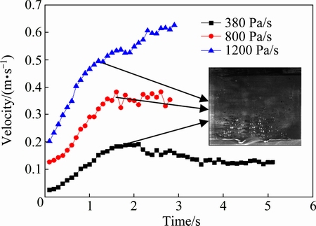
Fig. 4 Gate velocity in vacuum suction casting under different depressurizing speeds
The filling processes of water simulation under different depressurizing speeds are shown in Fig. 5. When the depressurizing speed is 380 Pa/s, the liquid flattens on the surface smoothly during the filling process. The velocity vector diagram shows that there is a jet zone above the ingate. In the whole jet zone, the velocity of the liquid emerging from ingate is almost the same as that of the surface above ingate. CAMPBELL [15] suggested that the critical velocity of water was 0.33 m/s. For depressurizing speed of 380 Pa/s, the ingate velocity is lower than the critical velocity. The inertia force induced by the jet is less than the surface tension of the liquid, thus resulting in the smooth advance of the liquid surface. Two vortexes on both sides of the jet zone lead to the horizontal flow of the liquid below free surface during filling process. Meanwhile, the entrainment of surface oxide film can be effectively avoided.
Figure 5(b) shows the filling process under depressurizing speed of 800 Pa/s. Liquid surface is also as smooth as that at depressuring speed of 380 Pa/s during the spreading stage. At the beginning of the filling stage, the gate velocity reaches 0.35 m/s which is higher than the critical velocity of 0.33 m/s. The liquid can rise as a jet with sufficient height, and then fall back under gravity which will result in the air entrapment.
For the depressurizing speed of 1200 Pa/s, liquid surface with more obvious convex curvature above ingate induced by the jet flow is observed in the spreading stage, as shown in Fig. 5(c). And the air entrainment occurs in the spreading stage for the gate velocity higher than the critical velocity. This means that the intensity of the jet effect is stronger than those of two previous depressurizing speeds and more air is involved in bulk fluid in the filling stage.
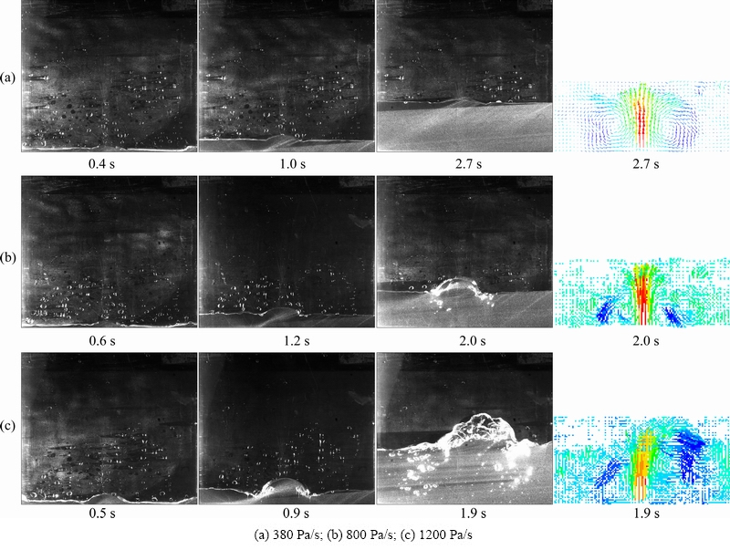
Fig. 5 Water simulation results of entrainment behaviors in sudden expansion structure under different pressurizing speeds
3.2 Depressurizing speed design
Reasonable depressurizing speed will ensure that the gate velocity in mold filling process is lower than critical velocity. It is assumed that the liquid surface in the cavity during filling stage remained horizontal plane, the filling stage can be described by using the Bernoulli��s equation as
 (5)
(5)
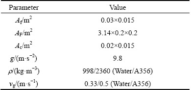
where H0 is initial depth of riser tube insert in molten metal in crucible, L is the initial height from the liquid surface in furnace to the bottom of the cavity, AF is cross-section area of crucible, Af is cross-section area of riser tube, Ac is the cross-section area of cavity, g is gravity, �� is density of molten metal, vF is descent velocity of liquid metal in crucible, the vc is the rising velocity of liquid metal in cavity, y is height of molten metal in cavity, P0 is ambient pressure (reference pressure), P(t) is pressure function of time, and �� is local resistance coefficient. Figure 6 shows the schematic diagram of the filling stage in vacuum suction casting.
In Eq. (5), there are
 (6)
(6)
 (7)
(7)
 (8)
(8)
After derivation, the equation is expressed as follows:
 (9)
(9)
Refer to the conservation of volume flow rate:
 (10)
(10)
where vg is gate velocity.
Combining Eqs. (9) and (10), depressurizing speed can be expressed as
 (11)
(11)
It is clear that Eq. (11) contains the factors of the ratio on cross-section area in the furnace, riser tube and mould cavity, which lead to the velocity change in mold filling process.

Fig. 6 Schematic diagram of filling stage under vacuum suction casting
According to water simulation results and previously reported data [15], the gate velocity of water in filling stage should be lower than 0.33 m/s. According to Eq. (11), the depressurizing speed should be lower than 470 Pa/s for ensuring the gate velocity lower than critical value during mold filling. Thus, when the depressurizing speed is 380 Pa/s (lower than 470 Pa/s), there is no air entrapment in the mold filling process in present work.
The velocity vector diagrams (as shown in Fig. 5) show that the submerged jet zone is formed, which includes the area from the ingate to liquid free surface. In the submerged jet zone, the velocity of the fluid almost keeps unchanged, because the buoyant force of the fluid particles is equal to its weight. Furthermore, it can be considered that the inertia force acts on the liquid free surface directly. When the inertia force is equal to surface tension, the critical velocity is 0.33 m/s [9]. Therefore, when the experimental condition varies in sudden expansion structure in ASC, the gate velocity should still be lower than 0.33 m/s in the filling stage.
Table 2 Parameters of model used in Eq. (11)
3.3 Casting experiment results
BAHREINIAN et al [16] and RUNYORO et al [17] suggested that the critical velocity of aluminum was 0.5 m/s. Substituting the critical velocity value into Eq. (11), the calculated depressurizing speed should be lower than 1776 Pa/s in the mold filling process. In present work, three different depressurizing speeds were designed as 1, 2 and 3 kPa/s, respectively.
3.3.1 Bend test and reliability analysis
Using the mechanical data of ultimate bending strength (��UBS) of the castings under different depressurizing speeds, two- and three-parameter plots of Weibull distributions are constructed and demonstrated in Fig. 7. Table 3 shows the parameters for the curve fittings and their R-squared values. Based on the R-squared values of curve fitting, both two- and three- parameter plots are both suitable for different depressurizing speeds. The threshold value of 183 MPa for 1 kPa/s is much higher than 141 and 103 MPa for 2 and 3 kPa/s, respectively).
3.3.2 Fracture morphology
Figure 8 shows the fracture surface morphologies of specimens under different depressurizing speeds. The oxide film defects were observed on the fracture surfaces of the specimens with depressurizing speeds of 2 and 3 kPa/s. Figure 8 shows an oxide film containing oxygen, aluminum, and magnesium elements identified by EDX elemental mapping on the fracture surface. In Fig. 8(a2), element contents of oxygen and magnesium are 6.72% and 1.15%, respectively, while in Fig. 8(b2), their contents are 14.84% and 7.45%, respectively.
Obviously, oxide film entrainment will occur during the filling process under the unreasonable depressurizing speed in vacuum suction casting, which will show impact on the mechanical properties. The validity of Eq. (11) in aluminum alloy casting was verified by the experiment results.
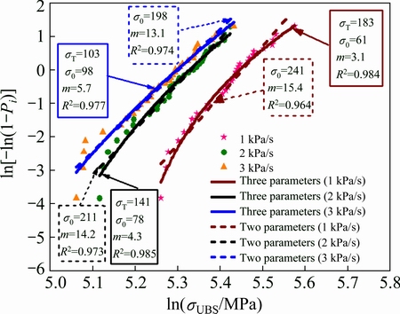
Fig. 7 Weibull distributions of four-point breaking stresses (units of ��0 and ��T: MPa)
Table 3 Two- and three-parameter of Weibull probability plots for three pressurizing speeds

4 Conclusions
1) The filling process of vacuum suction casting can be divided into spreading stage and filling stage. In the spreading stage, the gate velocity increased dramatically. In the filling stage, the gate velocity could keep unchanged which is lower than critical velocity under reasonable depressurizing speed.
2) In the filling stage, the effect of submerged jets makes the inertia force of the fluid particles flow from the ingate act on the liquid surface directly. Therefore, when the experimental condition varies in vacuum suction casting, the gate velocity should still be lower than critical velocity in the filling stage.
3) A new method to determine reasonable depressurizing speed is expressed as Eq. (11), which can help to eliminate the entrainment of oxide film in vacuum suction casting.

Fig. 8 Fracture morphologies under different depressurizing speeds
References
[1] CHANDLEY G D. Use of vacuum for counter-gravity casting of metals [J]. Material Research Innovations, 1999, 3(1): 14-23.
[2] LI Sheng-yong, LI De-jiang, ZENG Xiao-qin, DING Wen-jiang. Microstructure and mechanical properties of Mg-6Gd-3Y-0.5Zr alloy processed by high-vacuum die-casting [J]. Transactions of Nonferrous Metals Society of China, 2014, 24(12): 3769-3776.
[3] SHENG Li-yuan, ZHANG Wei, GUO Jian-ting, YE Heng-qiang. Microstructure and mechanical properties of Hf and Ho doped NiAl-Cr(Mo) near eutectic alloy prepared by suction casting [J]. Materials Characterization, 2009, 60(11): 1311-1316.
[4] COX M, HARDING R A, GREEN N R, SCHOLL G W. Influence of vacuum counter-gravity filling on reliability of 2L99 aluminium investment castings [J]. Materials Science and Technology, 2007, 23(9): 1075-1084.
[5] FOX S, CAMPBELL J. Visualisation of oxide film defects during solidification of aluminium alloys [J]. Scripta Materialia, 2000, 43: 881-886.
[6] MI J, HARDING R A, WICKINS W, CAMPBELL J. Entrained oxide films in TiAl castings [J]. Intermetallics, 2003, 11(4): 377-385.
[7] AFSHARPOUR M, HOMAYUN B, BOUTORABI S M A. Water modelling of effects of pouring basin and sprue geometry on entrance of air bubbles into mould [J]. Materials Science and Technology, 2014, 30(2): 152-159.
[8] SU Yan-qing, YE Xi-cong, GUO Jing-jie, FU Heng-zhi. Study on vacuum suction casting for TiAl-based alloys [J]. Rare Metal Materials and Engineering, 2009, 38(9): 1505-1508.
[9] CAMPBELL J. Castings [M]. Oxford: Butterworth-Heinemann, 1991: 11.
[10] CHEN Zhong-wei, ZHANG Hai-fang, LEI Yi-min. Secondary solidification behaviour of AA8006 alloy prepared by suction casting [J]. Journal of Materials Science and Technology, 2011, 27(9): 769-775.
[11] WANG Qing-liang, XIONG Shou-mei. Vacuum assisted high-pressure die casting of AZ91D magnesium alloy at different slow shot speeds [J]. Transactions of Nonferrous Metals Society of China, 2014, 24(10): 3051-3059.
[12] KAWAGUCHI Y, SEGAWA T, FENG Z P, LI P W. Experimental study on drag-reducing channel flow with surfactant additives�C�CSpatial structure of turbulence investigated by PIV system [J]. International Journal of Heat and Fluid Flow, 2002, 23: 700-709.
[13] HSU Fu-yuan, YANG Yao-ming. Confluence weld in an aluminum gravity casting [J]. Journal of Materials Processing Technology, 2012, 212(4): 825-840.
[14] TIRYAKIOGLU M, CAMPBELL J. Weibull analysis of mechanical data for castings: A guide to the interpretation of probability plots [J]. Metallurgical and Materials Transaction A, 2010, 41(12): 3121-3129.
[15] CAMPBELL J. Castings [M]. Oxford: Butterworth-Heinemann, 2003: 32.
[16] BAHREINIAN F, BOUTORABI S M A, CAMPBELL J. Critical gate velocity for magnesium casting alloy (ZK51A) [J]. International Journal of Cast Metals Research, 2006, 19(1): 45-51.
[17] RUNYORO J, BOUTORABI S M A, CAMPBELL J. Critical gate velocities for film-forming casting alloys: A basis for process specification [J]. Transactions of American Foundry Society, 1992, 37: 225-234.
��ѹ�ٶȶ��������A356�Ͻ������Ϊ������Ĥ������̵�Ӱ��
������1,2���ܸ���1,2������Ӣ1,2,3��������1,2���� ��1,2����־��1,2���」��1,2
1. ��������ҵ��ѧ ���Ͽ�ѧ�빤��ѧԺ�������� 150001��
2. ��������ҵ��ѧ ���������ȼӹ������ص�ʵ���ң������� 150001��
3. ���տƼ���ѧ ұ������Ϲ���ѧԺ���żҸ� 215600
ժ Ҫ���о���ѹ�ٶȶ��������A356�Ͻ������Ϊ������Ĥ������̵�Ӱ�졣��������ͼ�������ͨ��ˮģ�ⷽ���۲������Ϊ��������ٶȳ��ı仯���ɡ��������������������ǻ�����ٶ����ȿ������ӣ�������ż�ѹ�ٶȵIJ�ͬ�������ٶȵı仯���ֳ�3�ֲ�ͬ�������ѹ�ٶȽϴ�ʱ�������ٶȼ������ӣ���ѹ�ٶȺ���ʱ�������ٶȱ��ֲ��䣻��ѹ�ٶȽϵ�ʱ�������ٶ��Ƚ��ͺֲ��䡣�����ٶ�Խ������Խ���أ����������������»�����Һ��ʱ���ٶ�Խ�����ǵ��������������������Ĥ�������Ҫԭ���Ƶ��˼�ѹ�ٶȵ����ԭ�ݴ˽�ע��A356�Ͻ����������������ĵ�����ǿ�ȣ�������Τ��ͳ�������������Ŀɿ��ԣ�֤���˼�ѹ�ٶ����ԭ���ȷ�ԡ�
�ؼ��ʣ�A356���Ͻ����������ˮģ�⣻������������������������Ĥ
(Edited by Wei-ping CHEN)
Foundation item: Project (51375110) supported by the National Natural Science Foundation of Chain
Corresponding author: Jian-fei SUN; Tel: +86-451-86418317; E-mail: jfsun_hit@263.net; jfsun@hit.edu.cn
DOI: 10.1016/S1003-6326(16)64463-1

