Reinforcement by polyurethane to stiffness of air-supported fabric formwork for concrete shell construction
来源期刊:中南大学学报(英文版)2019年第9期
论文作者:龚景海 郭晓 钱圣申 卿强
文章页码:2569 - 2577
Key words:fabric formwork; polyurethane; stiffness; thin-shell structure; loading experiment; shell layered finite element
Abstract: By spraying concrete on inner surface, air-supported fabric structures can be used as formwork to construct reinforced concrete shell structures. The fabric formwork has the finished form of concrete structure. Large deviation from the desired shape of concrete shells still remains as central problem due to dead weight of concrete and less stiffness of fabric formwork. Polyurethane can be used not only as a bonding layer between fabrics and concrete but also as an additional stiffening layer. However, there is little research on mechanical behaviors of the polyurethane shell structure. This paper presents experimental studies on an inflated fabric model with and without polyurethane, including relief pressure tests, vertical loading tests and horizontal loading tests. Experimental results show that the additional polyurethane layer can significantly enhance the stiffness of the fabric formwork. Compared with the experiment, a numerical model using shell layered finite elements has a good prediction. The reinforcement by polyurethane to improve stiffness of air-supported fabric formwork is expected to be considered in the design and construction of the concrete shell, especially dealing with the advance of shape-control.
Cite this article as: GUO Xiao, QIAN Sheng-shen, QING Qiang, GONG Jing-hai. Reinforcement by polyurethane to stiffness of air-supported fabric formwork for concrete shell construction [J]. Journal of Central South University, 2019, 26(10): 2569-2577. DOI: https://doi.org/10.1007/s11771-019-4195-3.

J. Cent. South Univ. (2019) 26: 2569-2577
DOI: https://doi.org/10.1007/s11771-019-4195-3

GUO Xiao(郭晓), QIAN Sheng-shen(钱圣申), QING Qiang(卿强), GONG Jing-hai(龚景海)
School of Naval Architecture, Ocean and Civil Engineering, Shanghai Jiao Tong University,Shanghai 200240, China
 Central South University Press and Springer-Verlag GmbH Germany, part of Springer Nature 2019
Abstract: By spraying concrete on inner surface, air-supported fabric structures can be used as formwork to construct reinforced concrete shell structures. The fabric formwork has the finished form of concrete structure. Large deviation from the desired shape of concrete shells still remains as central problem due to dead weight of concrete and less stiffness of fabric formwork. Polyurethane can be used not only as a bonding layer between fabrics and concrete but also as an additional stiffening layer. However, there is little research on mechanical behaviors of the polyurethane shell structure. This paper presents experimental studies on an inflated fabric model with and without polyurethane, including relief pressure tests, vertical loading tests and horizontal loading tests. Experimental results show that the additional polyurethane layer can significantly enhance the stiffness of the fabric formwork. Compared with the experiment, a numerical model using shell layered finite elements has a good prediction. The reinforcement by polyurethane to improve stiffness of air-supported fabric formwork is expected to be considered in the design and construction of the concrete shell, especially dealing with the advance of shape-control.
Key words: fabric formwork; polyurethane; stiffness; thin-shell structure; loading experiment; shell layered finite element
Cite this article as: GUO Xiao, QIAN Sheng-shen, QING Qiang, GONG Jing-hai. Reinforcement by polyurethane to stiffness of air-supported fabric formwork for concrete shell construction [J]. Journal of Central South University, 2019, 26(10): 2569-2577. DOI: https://doi.org/10.1007/s11771-019-4195-3.
1 Introduction
Nowadays, 50%-60% of all used natural resources are consumed by construction industry, and in particular 40% of these resources are concrete [1]. Furthermore, the concrete industry, which is growing rapidly, is responsible for much of the carbon emission. Due to serious shortage of resources and environmental protection requirements, it is necessary to reduce the consumption of concrete. With advantageous load- bearing behavior, shells effectively utilize concrete properties and reduce the amount of required reinforcement. Shells are widely recognized suitable for constructing large area and volume, especially for some industrial storage facilities, such as coal, grain, cement and even chemistry.
However, traditional construction methods limit the application of shell structures. The complicated production and formwork of shell surfaces not only raises the cost but also consumes a large amount of time and labor. Therefore, how to optimize the construction method is the focus of current research. WOERD et al [2] have developed a new dome structure construction method in 2014, called Oridome, which was inspired by Origami. Along designed “creases”, precast concrete slabs are assembled and poured. GOWDA [3] has developed a kind of fabric formwork with standardized steel components for concrete roofs, which allow for complex forms of thin concrete shell structures. Although those methods could shorten construction period and avoid the difficulty of pouring traditional shell structure, the smoothness of shell surface is still not good enough.
Using the fabric formwork is one possibly way to not only reduce the effort required for formwork, but also ensure the smooth surface of the shell. A thin membrane is filled with air and serves as the supporting structure. The air-supported fabric formwork is used frequently, mainly employing the systems developed by NOSE [4, 5], HEIFETZ [6, 7], and SOUTH [8]. One of the first applications of inflatable formwork was patented in 1926 [4] and 1931 [5] by NOSE for the production of culverts and concrete pipes. He used tube-like inflatable structures, mounted them on outer frames, and filled the remaining space with concrete. Afterwards he deflated and removed the membrane. In 1969, HEIFETZ in Israel patented another construction method for the production of cost-efficient houses [6, 7]. Reinforcement is mounted on the outside of an air-supported fabric formwork and shotcrete is applied. A pressure of 4.0-10.0 kPa in the fabric formwork is used to minimize the deformations during concrete spraying. In 1979, SOUTH invented a further construction method for the production of concrete domes [8, 9]. Like others before him, he also sprayed concrete onto an inflated fabric formwork. In contrast to HEIFETZ, SOUTH mounted the reinforcement onto the inside of the membrane and improved the stiffness of the inflated membrane by applying an additional layer of polyurethane before the reinforcement and the concrete were applied. This polyurethane layer also serves as insulation.
Based on the system above, the construction of a reinforced concrete shell structure using fabric formwork is consisted of four processes: foundation and tunnels preparation, air formwork construction and inflation, spraying polyurethane, and reinforcing bar and concrete spraying. The construction method used by MONOLITHIC [10] is shown in Figure 1. After repeated inflation and deflation, air pressure in fabric form is stabilized at the designed value via air pressure control system, so as to form an appropriate formwork shape. Then, concrete shell is shaped by spraying special concrete on inner surface of fabric form. Obviously, the fabric form has the final shape of reinforced concrete shell structures. A deviation from the desired fabric formwork leads to varying deformations during the application of the concrete on the membrane and differing stresses in the concrete shell. Deformation control and the long time required to apply the concrete over the entire fabric formwork are still the main concern of researchers [11].
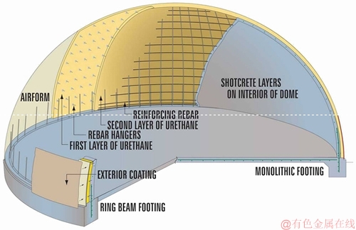
Figure 1 Schematic drawing of construction method used by MONOLITHIC [11]
Different modifications to improve the stiffness of fabric formworks in the past show that systems using an additional layer of polyurethane are most effective to build shells with large span. However, there is few studies on mechanical behaviors of the thin shell composed of polyurethane layers at present, so there is no reference available for actual design and construction. For instance, the coal storage of the coal preparation plant, with diameter of 54 m and height of 52.5 m, which were located in Cucurbitacin town, Wushenqi grams, Erdos city, Inner Mongolia, China, as shown in Figure 2. Although the design has considered the deformation deviation of fabric formwork during molding concrete shell, there is still a quite difference between the result and the prediction.
The polyurethane layer is usually known for thermally insulating and fixing bar-mat reinforcement. This paper puts forward a 1:10 reduced scale model for experimental study on mechanical behaviors of polyurethane thin-shells, on which there are very few relevant researches. The structure of this paper is organized as follows:
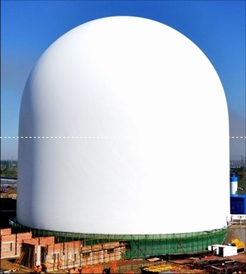
Figure 2 A photograph of a coal storage
In Section 2, material properties of the PVC-coated fabric are described and compression and tensile mechanical properties of polyurethane blocks are presented in details; In Section 3, vertical loading case, horizontal loading case and relief pressure case are performed to study the response of inflatable fabric formwork with and without polyurethane layer, and a prediction model using shell layered finite elements of SAP2000 is presented; In Section 4, load-displacement responses of the inflatable fabric formwork are compared with the composite formwork, and testing properties of polyurethane are verified by comparing numerical results with experimental performance; Finally, Section 5 presents the summary and conclusions.
2 Elastic properties measurement
2.1 Membrane
Architectural membrane used in this paper is Durask in B6915, a kind of PVC-coated fabrics, which is composed by coating polyvinyl chloride and polyvinylidene fluoride (PVC-PVCF) on the surface of base fabrics [12]. The base fabric, woven by polyester fiber yarns in warp and fill directions, is the main part that determines mechanical properties of PVC-coated fabrics. The warp yarns are first tensioned and fixed, and then the fill yarns are crossed up and down in the direction perpendicular to the warp, so as to form a base layer of fabric. This method makes the mechanical properties of membrane anisotropic[13]. PVC coating is mainly used to meet the requirements of waterproof, durability and other functions of membrane in buildings while protecting the basic fabric[14].
Our study on material model of the air-supported fabric structure under external load shows that membrane modulus decreases with the decrease of stress. On the basis of uniaxial and biaxial tensile tests [15-17], the modified material model established by considering this mechanical property can not only describe the effect of stress ratio on modulus, but also calculate the effect of stress decreasing on modulus. The elastic moduli  and
and  of Duraskin B6915 in warp and fill direction calculated by this material model is as follows [18]:
 (1)
(1)
 (2)
(2)
where the stress ratios in warp and fill direction are defined as [19]
 (3)
(3)
 (4)
(4)
and Poisson ratios are 0.309 and 0.197.
2.2 Polyurethane
The material of polyurethane used in the experimental model is from Wanhua EnergySav Science & Technology Group Co., Ltd., which consists of WANNATE 2208 and WANEFOAM 332. WANNATE 2208 is a kind of mixture made up of isocyanate and diphenyl methane diisocyanate with high functionality. This material has good bubble flow property before solidification, and it has good thermal insulation performance and strength after solidification. WANEFOAM 332 contains blowing agent and it is used to combination. This material has fast curing performance and strong cohesive stress. Used with WANNATE 2208, this combination of materials can obtain excellent flame retardant property.
Tests of polyurethane blocks show that density of the polyurethane was 33.5 kg/m3 in the case of non-pressure and it was 36.2 kg/m3 under the air pressure of 600 Pa. It shows that growth of internal air pressure will increase density of polyurethane. Then, the results of compression and tensile tests indicate that mechanical properties of polyurethane will change with the increase of density. Photographs in Figure 3 are the polyurethane specimens in compression and tensile tests.
Mechanical properties of these tests are shown in Tables 1 and 2. In these tables, vertical direction is perpendicular to the plane of spraying layer, and parallel direction is parallel to the plane of spraying layer, as shown in Figure 4.
3 Loading experimental and finite element analysis
3.1 Description of loading tests
Loading tests are carried out on an air-supported fabric formwork with and without the polyurethane layer to quantify the reinforcement by polyurethane layer to improve the stiffness of the entire formwork. In this paper, the fabric formwork without polyurethane layer is named as Model-1, and the fabric formwork with polyurethane layer is named as Model-2. Global dimensions of testing model are shown in Figure 5.
Tests of inflatable membrane structure need to be equipped with proper fans and control system [20]. Fans are selected to supply air, and real-time air pressure values are passed to an air pressure sensor through a thin flexible tube connected inside and recorded at a frequency of 1 group/second. Photographs show the software for reading and storing real-time air pressure information and controlling the frequency conversion equipment. Through the frequency control system, power of fans can be adjusted according to the real-time air pressure to stabilize the air pressure.
As shown in Figure 6, a steel ring is attached to the top of experimental model to apply vertical loads and horizontal loads. The area circled by the steel ring is called Spherical Cap. In vertical loading, sandbags are evenly placed on the spherical cap. In horizontal loading, sandbags are placed in a steel basket and vertical loads are converted to horizontal loads by a fixed pulley mounted on a scaffold.
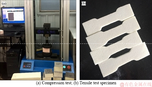
Figure 3 Photographs of polyurethane specimen:
Table 1 Compression mechanical properties of polyurethane specimen
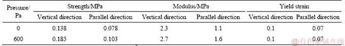
Table 2 Tensile mechanical properties of polyurethane specimen
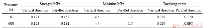
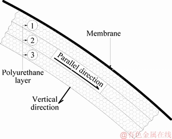
Figure 4 Schematic diagram of layered polyurethane structure
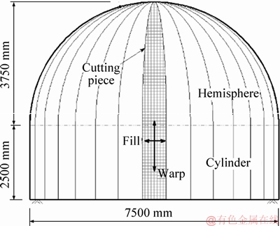
Figure 5 Global dimensions of testing model
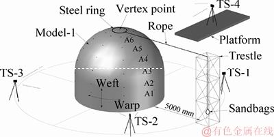
Figure 6 Experimental schematics
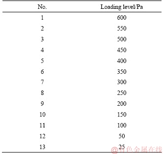
Three loading cases are involved in tests to evaluate the effect of polyurethane layer on strengthening stiffness of formwork, including relief pressure case, vertical loading case, and horizontal loading case. All loading cases involve load-displacement tests on the Model-1 and the Model-2. In relief pressure case, compression forces are evenly distributed on the polyurethane thin-walled structure with decreasing air pressure. The object of this case is to study the resistance of polyurethane thin-walled structure to deformation under global compression. The vertical force and horizontal force are two major loads for inflatable fabric structures, and two photographs in Figure 7 present the status that experimental models are applied vertical loads and horizontal loads at the Spherical Cap. The objects of these two cases are to assess the reinforcement by polyurethane layer to vertical and horizontal stiffness of fabric formwork. Loading history of these tests is listed in Tables 4 and 5.
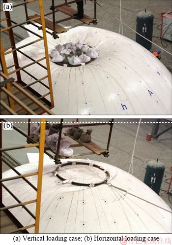
Figure 7 Photographs of specimens in two loading cases:
Table 4 Loading history of vertical loading case and horizontal loading case
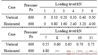
Table 5 Loading history of relief pressure case
After all tests for Model-1, the polyurethane is sprayed evenly on internal surface of membrane, and then tests of Model-2 are carried out. Here, spraying of polyurethane is finished by three times and each time is full of a layer with 10 mm in thickness at a pressure of 600 Pa.
3.2 Finite element analysis
For theoretical analysis of the Model-2, shell layered finite element in SAP2000 V14 (Software Integrates for Structural Analysis & Design) is adopted to mesh numerical model [21]. Based on mechanics of composite materials, a shell element is layered and each layer can be set with different thickness and material properties as required, such as membrane and polyurethane layer [22]. The coupling between in-plane bending, in-plane shear and out-of-plane bending is considered in the shell layered element, which reflects the spatial mechanical properties of composite shell structures comprehensively.
Physical properties of materials are defined by the tensile and compression tests addressed in Section 2. Corresponding to the parallel direction modulus, elastic modulus of the polyurethane for 600 Pa is 1.65MPa.
4 Results and discussion
In relief pressure case, external surface of the polyurethane thin-walled structure will be subjected to more and more out-of-plane pressure due to fabric shrinkage with decreasing internal air pressure. By comparing load-displacement responses of the Model-1 and the Model-2, the thin- walled structure made of solidified polyurethane shows a good performance in integrity. There is no any local failure occurred in the polyurethane structure during the air pressure reduced from 600 Pa to 20 Pa.
Figure 8 plots the experimental and computational load-displacement curves of the models in relief pressure case. It can be seen that the experimental load-displacement curves display moderate nonlinear character. As shown in Figure 8, vertex deflection of the Model-2 is far less than that of the Model-1. When the air pressure is 200 Pa, the vertical displacement of Model-2 is about 1 mm, which is far less than the 14 mm of Model-1. This indicates that the polyurethane thin-walled structure has good vertical bearing capacity as a shell. The curves shown in Figure 8 are horizontal displacements of the measurement point on sidewall of the lower cylinder. When the air pressure is 200 Pa, horizontal displacement of the Model-1 is 12.1 mm, which is similar to the value of vertex deflection. After the addition of polyurethane layer, horizontal displacement of the Model-2 is reduced to 4.6 mm. Experimental results show that the polyurethane thin-walled structure is obviously helpful to improve the out-of-plane stiffness of cylinder structure, although it is not as good as shell structure due to different structural characteristics of themselves. In general, the polyurethane thin-walled structure has ability to carry the loads of structural self-weight and membrane shrinkage, and has some load allowance depending on the result of the load-displacement curves.
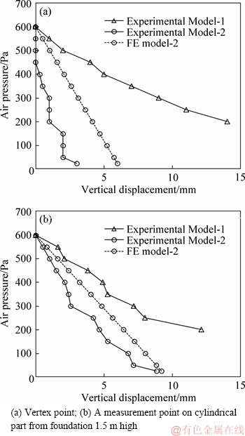
Figure 8 Load-displacement curves of 1:10 model in relief pressure case showing comparison of air-supported fabric formwork with and without polyurethane layer:
Finite element predictions in relief pressure case are compared with the experimental observations as shown in Figure 8. For vertical displacement in Figure 8, the finite element results do not agree very well with the test data and the average displacement difference is 2.3 mm. This may be because the measured elastic modulus of polyurethane is smaller than the actual value. However, it is more because of the amplification by small displacement values and the limitations of measurement methods. In the same way, the average displacement difference between predicted and measured is 1.3 mm for horizontal displacement in Figure 8.
In vertical loading case, vertex deflection of Speicmen-1 rose slowly and evenly with the increase of loads until the loading level reached to 0.65 kN. After the loading level 0.65 kN, increase of the vertex deflection suddenly became quite obvious, and the top area of hemispherical part already became concave; for the Model-2, there was no indentation at the spherical cap during the entire loading process.
As shown in Figure 9, the measured experimental data in vertical loading case indicates that the curve of Model-1 has inflection when loaded to 650 N(589.7 Pa) and the corresponding displacement is 23 mm. In contrast, the curve of Model-2 shows moderate nonlinear characteristics, and the vertex deflection is only 12 mm until the model is loaded to 1000 N (907.2 Pa). At the loading level of 650 N, the vertex deflection of Model-2 is 3.1 mm that is approximately 1/8 of the vertex deflection of Model-1. Apparently, the shell of polyurethane significantly improves the vertical stiffness of the entire formwork structure.
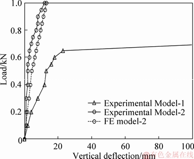
Figure 9 Load-displacement curves of vertex point in vertical loading case: A comparison of air-supported fabric formwork with and without polyurethane layer
For the Model-1 in horizontal loading case, membrane wrinkling (bottom wrinkles) appears at the bottom of cylindrical part at the loading level of 3.2 kN. The bottom wrinkles are concentrated in the side facing the loading trestle. Some other membrane wrinkles (tilted wrinkles) are tilted along the horizontal loading direction from the bottom of the fabric formwork to the top, which appears from the loading level of 4.8 kN. The tilted wrinkles spread widely and evenly in fabrics and the wrinkling wave is shallow unlike the concentrated and deep bottom wrinkles. For the Model-2, there are no wrinkles appeared in the entire loading process.
Figure 10 plots the experimental load-displacement curves of the specimens in horizontal loading case. It can be seen that both curves show moderate nonlinear characteristics. Horizontal displacement of the Model-2 is approximately 1/8 of the Model-1. In addition, the shell of polyurethane significantly improves the horizontal stiffness of the entire formwork structure.
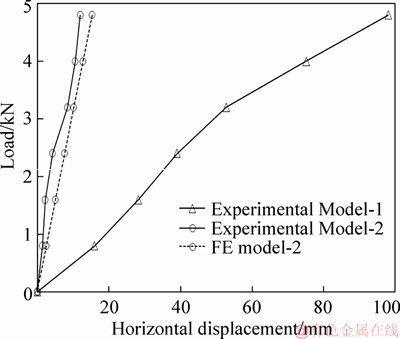
Figure 10 Load-displacement curves of vertex point in horizontal loading case: A comparison of air-supported fabric formwork with and without polyurethane layer
In addition, finite element predictions in loading cases are compared with the experimental observations as shown in Figures 9 and 10. It is seen that the finite element results agree well with the test data and the average displacement difference for vertical loading case is 2.4 mm and for horizontal loading case is 2.4 mm, respectively. Then, the measured elastic modulus of polyurethane also appears to be smaller than it actually is.
5 Summary and conclusions
Compression tests of polyurethane blocks indicate that strength and modulus are related to the air pressure during spraying, while the yield strain not. The compression strength will be increased by 30%-35% when the air pressure is higher than the atmospheric pressure with 600 Pa, and the strength in vertical direction is 70%-80% higher than that in parallel direction. The compression modulus increases with the rise of air pressure in both directions, and the modulus in vertical direction is almost twice it in parallel direction. In tensile tests, increase in strength and modulus of polyurethane is similar to compression test in parallel direction with the rise of air pressure. However, due to the process of multi-layer spraying, strength, modulus and braking strain of polyurethane blocks in vertical direction have different degrees of decrease. Overall, the air pressure in construction will increase the density of polyurethane, and increase of the density will enhance the elastic modulus of polyurethane itself and then the overall stiffness of the polyurethane shell structure.
In the process of reducing air pressure, there is no local damage occurring on the entire polyurethane shell structure, and even the deformation is very small. It demonstrates that the polyurethane shell structure can be used as an independent bearing structure with good integral rigidity. The excellent load-bearing performance of upper shell indicates that the shape of shell is well formed. For the vertical and horizontal loading tests in this paper, stiffness of the composite formwork made of inflated fabrics and polyurethane layer is about 8 times that of inflated fabric formwork. Obviously, polyurethane can effectively reinforce the stiffness of the air-supported fabric formwork. Compared with the experiments, a numerical model using shell layered finite elements has a good performance. However, the compared results indicate that the measured elastic modulus of polyurethane is smaller than the actual value. We look forward to improve the measurement method of mechanical parameters of polyurethane.
Polyurethane coat inside the air-supported fabric can be not only used as thermal insulation and flame retardant material, but also as a part of formwork to mold concrete structures. The addition of polyurethane layer to the rigidity of falsework should not be ignored in the design of concrete shell structures using inflatable fabric formwork system. In future work, we will continue to analyses the interaction between fabrics and polyurethane layer and propose an effective calculation model to improve the accuracy of deformation control.
Acknowledgments
Beijing Z&T Fabric Architecture Technology Co., Ltd is acknowledged for providing the membrane materials and assisting with the experiments.
References
[1] SOBEK W. Ultraleichtbau [J]. Stahlbau, 2014, 83(11): 784-789.
[2] WOERD J D, CHUDOBA R, HEGGER J, BONGARDT C. Oridome: Construction of a dome by folding [C]// Proceedings of the IASS-SLTE 2014 Symposium. Brasilia, Brazil, 2014: 1-8.
[3] GOWDA B. Fabric forms for steel and for cement roofs [C]// Proceedings of the IASS-SLTE 2014 Symposium. Brasilia, Brazil, 2014: 1-8.
[4] NOSE T. Process of constructing cultures of pipes of concrete: U.S. Patent 1, 600, 353 [P]. 1926.
[5] NOSE T. Apparatus for construction concrete culverts: U.S. Patent 1, 964, 286. [P]. 1931.
[6] HEIFETZ H. Domecrete building system (Israel), “Bauen+ wohnen = construction + habitation = building + home” [J]. Internationale Zeitschrift, 1972, 26(6): 262-263.
[7] HEIFETZ H. Inflatable forms: U.S. Patent 3, 643, 910, [P]. 1972.
[8] SOUTH D B. Economics and thin shell dome [J]. Concrete International, 1990, 12(8): 18-20.
[9] NEIGHBOR N, SOUTH D B. An evaluation of the monolithic dome construction method for biological containment structures [J]. Applied Biosafety, 1997, 2(1): 39-46.
[10] DOERSTELMANN M, KNIPPERS J, KOSLOWSKI V, et al. ICD/ITKE research Pavilion 2014-15-fibre placement on a pneumatic body based on a water spider web [J]. Architectural Design, 2015, 85(5): 60-65.
[11] KROMOSER B, HUBER P. Pneumatic formwork systems in structural engineering [J]. Advances in Mater Sci and Eng, 2016(6): 1-13.
[12] QIANG Q, QU G Z, SHEN S S, GONG J H. Theoretical analysis and experimental study of inflation forms of air-supported membrane formwork for concrete shell construction [C]// IASS 2015. Annual International Symposium on Future Visions. 2015: 1-16.
[13] TESTA R B, YU L M. Stress-strain relation for coated fabrics [J]. Journal of Engineering Mechanics, 1987, 113(11): 1631-1646.
[14] COLMAN A G, BRIDGENS B N, GOSLING P D. Shear behaviour of architectural fabrics subjected to biaxial tensile loads [J]. Compos Part A: Appl Sci Manuf, 2014, 66(4): 163-174.
[15] BLUM R, B GNER H, N
 MOZ G. Testing methods and standards, [M]// FORSTER B, MOLLAERT M. Tensinet European design guide for tensile surface structures. Brussel: Tensinet, 2004: 293-322.
[16] BGNER-BALZ H, BLUM R. The mechanical behaviour of coated fabrics used in prestressing textile engineering structures: Theory, simulation and numerical analysis to be used in a FEM-model [J]. J Int Assoc Shell Spatial Struct, 2008, 49(1): 39-47.
[17] MSAJ (Membrane Structures Association of Japan). Testing method for elastic constants of membrane materials. MSAJ/M-02-1995 [S].
[18] GUO Xiao, QING Qiang, GONG Jing-hai, ZHANG Li. A modified material model describing the load-deflection behavior of air-supported fabric structure with decreasing stress [J]. Thin-Walled Structures, 2018, 124: 384-391.
[19] GALLIOT C, LUCHSINGER R H. A simple model describing the non-linear biaxial tensile behaviour of PVC-coated polyester fabrics for use in finite element analysis [J]. Compos Struct, 2009, 90(4): 438-447.
[20] LI Qing-song, QING Qiang, GONG Jin-hai. A simple analytical method for deflation prediction of inflatable structures [J]. Journal of Central South University, 2015, 22(6): 2277-2286.
[21] HE S, CHEN Q, JIANG Z. Nonlinear buckling analysis for a trimmed irregular Kiewitt single-layer spherical shell structure [J]. Journal of Central South University, 2015, 46(2): 701-709.
[22] MINDLIN R D. Influence of rotatory inertia and shear on flexural motions of isotropic, elastic plates [J]. Journal of Applied Mechanics,1951, 18: 31-38.
(Edited by HE Yun-bin)
中文导读
聚氨酯层对气膜模板刚度的强化作用
摘要:通过内部喷射混凝土的方法,气承式充气膜结构可以被用作建造混凝土薄壳结构的模板。气膜模板施工变形后的形状决定了混凝土薄壳结构的最终形态,而较小的模板刚度将导致混凝土凝固成形后薄壳结构的形态与设计值偏差较大。实际施工情况表明,气膜模板中用作结合层使用的聚氨酯层可以为其提供一定的刚度,然而,与聚氨酯层力学性能相关的研究却很少。本文对气膜模板喷涂聚氨酯前后的模型分别进行了泄压、竖向加载和水平加载的试验研究,对比结果表明聚氨酯层可以显著增强气膜模板试验模型的刚度。采用分层壳单元进行的非线性有限元数值模拟的结果与试验现象较为吻合。在气膜钢筋混凝土结构的设计和施工中应当考虑聚氨酯层对气膜模板刚度的强化作用,尤其在提升结构形态控制方面。
关键词:气膜模板;聚氨酯;刚度;薄壳结构;荷载试验;分层壳单元
Foundation item: Projects(51178263, 51378307) supported by the National Natural Science Foundation of China
Received date: 2017-12-25; Accepted date: 2018-12-07
Corresponding author: GONG Jing-hai, PhD, Professor; Tel: +86-21-34207998; E-mail: gongjh@sjtu.edu.cn; ORCID: 0000-0003-1603- 9498

