
Morphology, structure and formation mechanism of silicide coating by pack cementation process
XIAO Lai-rong(肖来荣), CAI Zhi-gang(蔡志刚), YI Dan-qing(易丹青), YING Lei(殷 磊),
LIU Hui-qun(刘会群), HUANG Dao-yuan(黄道远)
School of Materials Science and Engineering, Central South University, Changsha 410083, China
Received 10 April 2006; accepted 25 April 2006
Abstract: The MoSi2 coating on C103 niobium based alloy was prepared by pack cementation method. The formative mechanism, morphology and structure of coating were investigated. The silicide coating was formed by reactive diffusion obeying parabolic rule during pack cementation process. It is found that the composite structural coating is composed of three inferior layers as follows. The main layer is composed of MoSi2, the two phases’ transitional layer consists of NbSi2 and a few Nb5Si3 and the diffuse layer is composed of Nb5Si3. The dense amorphous glass layer formed on the surface at high temperature oxidation circumstance can effectively prevent the diffusion of oxygen into coating.
Key words: niobium based alloy; pack cementation; silicide coating; formative mechanism
1 Introduction
Nb-based alloys have been used as important high temperature structural materials due to their high melting point and good high temperature strength[1, 2]. However, the poor high temperature oxidation resistance properties become an inevitable obstacle in application[3, 4]. As the requirement of new two-component orbit attitude controlled engine, Nb-based components should be endured at high temperature circumstance longer. Therefore, the studies of corresponding high temperature oxidation resistance coating get more and more attractive. With high melting point, moderate density and excellent high temperature oxidation resistance properties, MoSi2 becomes one of important candidate materials which can be applied as protective coating on refractory alloys and C/C composites [5, 6].
RYOSUKE et al [6-8] used melting salt, laser fused and CVD method respectively to produce MoSi2 coating on molybdenum and alloyed steel substrates. In the present work, MoSi2 coating was produced on C103 Nb alloy by preparing a Mo layer using slurry firing technology with subsequently packed silicide cementation treatment. The formation mechanism of coating during silicification, characterizations of surface and crossed-section, transformation of structures after oxidation were investigated to provide benefic references for improving the properties of coating.
2 Experimental
C103 Nb alloy with composition of 89Nb-10Hf-1Ti was cut into d 3 mm×40 mm sheets as specimens. After grinding, the specimens were treated by alkali solution, ultrasonic cleaning in ethanol, acid solution and distilled water respectively. Then the treated specimens were left in the drying chamber until the surface was dry.
Slurry was produced by ball milling Mo powder of 3.3 μm in diameter with ethanol in stainless steel milling medium. C103 Nb alloy specimens were dipped into the slurry and sintered in vacuum atmosphere to form a Mo layer on surface. Then the final MoSi2 coating samples were prepared by pack cementation process.
Static oxidation testing were carried at 1 600 ℃ in air. Analysis balance was used to measure the liveweight of coating samples at different time during pack cementation process. XD98 X-ray diffraction analysis was used to identify the phases on surface of coating. Morphologies of surface and cross-section of coating were observed by scanning electronic microscopy (SEM). Energy analysis was carried out to investigate the distribution of compositions in surface and cross-section of coating. The transformations of compositions and structures were compared between original and oxidized MoSi2 coating samples.
3 Results and discussion
3.1 Morphology on surface
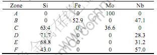
SEM images and X-ray diffraction patterns of original and oxidized MoSi2 coating samples are shown in Fig.1 and Fig.2 , EDS data are listed in Table 1, respectively. As we can see from Fig.1(a), the surface of Mo coating is relatively smooth after vacuum sintering except some tiny holes. The diameter of bigger hole can reach 3 μm. There are a few spherical particles composed of Fe, Ni and Cr on surface of Mo coating. These contaminations may be introduced by stainless

Fig.1 SEM images of Mo layer (a), Silicized layer (b) and Oxidated layer (c) at 1 600 ℃ for 10 h
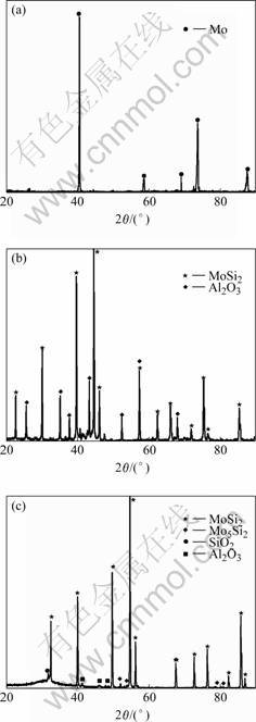
Fig.2 XRD patterns of surface: (a) Mo layer; (b) Silicided coating; (c) Oxidated coating
Table 1 EDS data of different zones on coating surface(mole fraction, %)
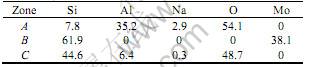
steel milling medium during milling process. The eutectic phases with relatively low melting point introduced by contaminations form sphere on the surface of Mo coating after solidification at a high temperature. Fig.2(b) shows that the surface of silicified Mo coating consists of MoSi2 and Al2O3 phases. EDS data show that the half spherical particles are composed of Al and O elements caused by Al2O3 particles in cemented powder during high temperature processing. A small quantity of Si and Na are also found in Al2O3 as contaminations. Fig.2(c) shows the oxidized coating surface consists of MoSi2, Mo5Si3 and amorphous phases composed of Si, O and Al elements. A dense oxidized film with smooth surface is formed on coating after oxidation (Fig.1(c)). The low melting point eutectic phase is created by the reaction between Al2O3 and SiO2 from the oxidation of MoSi2[9]. In Fig.2(c), an amorphous bump can be found in a low angle diffraction area. The oxidized samples were rapidly cooled to room temperature, causing the melting oxides rapid solidification into amorphous glass. Due to the great gap of thermal expansion coefficient between amorphous phases(a(SiO2) =2.4×10⁻⁶/℃) and MoSi2(a(MoSi2)=8.1×10⁻⁶/℃), some micro cracks can be found on the coating’s surface after rapid cooling form high temperature (Fig.1(c)).
3.2 Morphology of cross-section
As shown in Fig.3 (a), Mo layer, whose thickness is about 35 μm, is dense except some cavities inside. The transitional layer with deep color between Mo layer and substrate is composed of Nb, Fe and small quantities of Ni elements as listed in Table 2. The contaminations, such as Fe and Ni, were come from the milling of Mo powder. Compared to Mo, the self-diffusion coefficients of Fe and Ni are higher but the activated diffuse energy is lower [10]. Consequently, the contaminated elements in Mo layer diffus to substrate and out-layer and form two segregated areas. The Fe element diffuses to out-layer and forms the spherical shape low melting point eutectic phases on surface after cooling as shown in Fig.1(a).
The morphology of coating’s cross-section after silicification is shown in Fig.3 (b). The coating’s thickness increases to 125 μm after pack cementation, due to the silicates increased by reactive diffusion. Some cavities caused by incompletely sealing of relatively big cavities in Mo layer can be found in out-layer of coating. From outside to inside, the coating can be divided into main layer, micro cavities zone and diffused layer. The main layer composing of MoSi2 with about 75 μm is dense.
The micro cavities zone with about 15 μm in thickness is formed by the aggregation of vacancy during the process of reactive diffusion. During the process of Si atom diffuses through MoSi2 layer and Nb substrate, vacancy source is generated and formed the dislocation creep deformations which are impelled by stress, where is created in new phase layer following its volume changed [11]. In the early stage of reactive diffusion, non-equilibrium vacancy distributes on the whole new thin layer.
With the proceeding of reactive diffusing, the concentration of vacancy increases gradually in interface. After diffusion, a low energy area appeares at the interface between MoSi2 and NbSi2 layers to create many vacancy traps. The consequential vacancy zone is formed for the aggregations of vacancies. TORTORICI et al [12] also found the similar phenomenon between Mo5Si3 and Nb5Si3 in diffusion couple of MoSi2/Nb. The formation of cavity zone can effectively release the thermal stress inside the coating, and then decreases the possible creat-

Fig.3 Cross-section morphology: (a) Mo layer; (b) Silicide coating; (c) Micropore zone; (d) Interlayer of silicide coating
ion of inner micro crack. On the other hand, the cavity zone is one of weaknesses for its relative lower strength. The mechanical properties of coating may be degraded under the flushing of high velocity and temperature flow due to the shear stress acting on cavity zone.
As shown in Fig.3(d), the bright layer closing to substrate with a straight interface and 2 μm in thickness is Nb5Si3. The dark area is NbSi2 phases with a few Nb5Si3 phases. After cooling to room temperature, Nb5Si3 separates out and deposites from NbSi2 to form the two phases’ transitional layer, due to its solid solution decreasing. As we known from Nb-Si binary phase diagram, NbSi2 and Nb5Si3 coexist in the range from 37% to 67% in mole ratio. The similar phenomenon is also found by CHIARA et al[13] in Nb/Si diffuse couple. The growing direction of needle shape Nb5Si3 phases in two phases’ transitional layer is perpendicular to the interface of coating, corresponding to the diffuse direction of Si in Nb substrate.
Table 2 EDS data of different zones in cross section(mole fraction, /%)
Dense Nb5Si3 phases with high strength and stiffness can prevent the further extension of cracks as illustrated in Fig.3(d). The precipitation of Nb5Si3 improves the strength of NbSi2 layer which also can resist the oxidation after the inactivation of main layer [14]. Nb5Si3 phases, which distributes near the interface between transitional layer and diffuse layer, improves the thermal shock resistance properties of coating whereby strengthens the combination of interface.
The whole thickness of coating increases to 180 μm after oxidation, and the dense oxidative film which is formed on the surface of coating reaches to 20 μm (Fig.4(a)). From EDS data and XRD patterns, oxidative film is composed of SiO2 and a small quantity of Al2O3. After the formation of oxidative film, the process of oxidation is controlled by the diffusion of oxygen through the oxidation. The diffuse rate of oxygen in SiO2 and Al2O3 is so slow that the oxidation resistance is improved by this dense oxidative film[14]. The cavity layer still exists between the main layer and transitional zone, but the micro cavities have come into bigger holes. The thickness of Nb5Si3 increases from 2 to 46 μm after oxidation, due to the Si in Si rich layer diffusing to substrate driven by chemical potential gradient. At the same time, Si diffuses to outer layer to remedy the loss in main layer. The reverse flow of vacancy achieves, the diffusion of Si and also can be aggregated by vacancy traps.
Because of the stronger appetency of oxygen with Hf in substrate, the dispersed HfO in white color are formed preferentially when the oxygen diffuses into coating or substrate (Fig.4(b)).
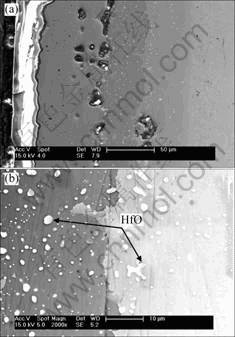
Fig.4 Cross-section morphologies of coating oxidated at 1 600 ℃ for 10 h (a) and interface between NbSi2/Nb5Si3 (b)
3.3 Formation process of coating
Pack cementation method to prepare the MoSi2 coating on Nb substrate includes two independent processes. The first procedure is to prepare Mo layer on Nb substrate by immersing or spraying the Mo slurry, and then followed with vacuum sintering. The second process is pack cementation to silicify. Halide activated pack cementation method is the combination of high temperature chemical vapor deposition and reactive diffusion. The reactive procedures as follows[15, 16]. 1) NaF reacts with silicon powder to form volatile SiF2; 2) The gaseous halide diffuses to the surface of Mo layer through porous pack driven by chemical potential gradients; 3) MoSi2 layer is formed by reactive diffusion of Si and Mo; 4) The chemical potential gradient of gaseous SiF2 is kept by the consume of deposition elements due to the growth of MoSi2 layer, subsequently the process of vapor diffusion is carried on; 5) The thickness of MoSi2 layer increases with the processing of Si deposition and reaction on Mo layer which is driven by chemical potential. The following is the procedures of vapor deposition [16, 17]:
2NaF+Si SiF2(g)+2Na (1)
2SiF2(g)SiF4(g)+Si (2)
5Mo+3Si Mo5Si3 (3)
Mo5Si3+7Si 5MoSi2 (4)
As known from the analysis above, the growth of coating is controlled by two processes: one is the gas flux of halide reaching on surface of Mo layer; the other is the growth rate of MoSi2 during the reactive diffuse between Si and Mo.
The gas flux of halide reaching on the surface of Mo layer can be denoted as
 (5)
(5)
where Di is the coefficient of gaseous diffusion;ΔPi/ΔX is the partial pressure gradient on substrate’s surface. With fixed Di and sintering processing parameter, and the Si which is used to form gaseous SiF2 in pack powder is always enough, then the gas flux of halide reaching on surface of Mo layer is a fixed value under the invariable partial pressure gradient [17].
During the practicable pack cementation process, the reactions (1) and (2) are controlled by the equilibrium partial pressure of SiF2 and SiF4 which relate to the consumption rate of Si or the growth rate of coating. Fig.5 shows the relative curve between gained mass on coating surface and time of silicification. As the time of pack cementation increases, the mass gained in unit area of coating increases, but the rate of mass gained decrease obeys the parabolic rule, which shows that the formation process of coating is controlled by reactive diffusion.
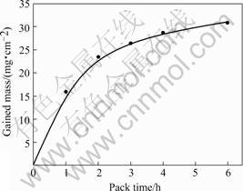
Fig.5 Relationship between gained mass and pack time
The formation of new phase is decided by its chemical stability and diffuse dynamics during the process of reactive diffusion. Because the formative enthalpy of Mo5Si3 is lower than that of MoSi2, during the instantaneous time of beginning of reaction, Si and Mo react to form a thin Mo5Si3 layer which is defined as reaction 3. As the proceeding of Si diffusion, MoSi2 layer is formed. The following reactive diffusion is controlled by the diffuse rate of Si through the MoSi2 layer. The front of Mo5Si3 layer is moving to Mo layer as the interface of reactive diffusion. After the whole Mo layer transforms into MoSi2 phases, the Si begins to diffuse into the substrate. The diffusion of Si is achieved by the reverse flow of vacancy, and subsequent micro cavity layer is formed by the aggregation of vacancy between the MoSi2 layer and substrate. Because of the formative enthalpy of Nb5Si3(-516.8 kJ/mol) is lower than that of NbSi2’s(-161 kJ/mol)[18], the Nb5Si3 layer forms firstly by reaction of Nb and Si which diffuses through MoSi2. As the proceeding of reactive diffusion, Si reacts with Nb5Si3 to form NbSi2, and the front of Nb5Si3 phase layer moves to substrate as reactive interface. The diffuse rate of Si in substrate is lower than before because of it is controlled by diffuse rate of Si in both MoSi2 and NbSi2. Furthermore, the diffuse path prolongs with the increase of coating’s thickness, as well as the time for diffusion of Si reaches the reactive interface. Effected by the decrease of reactive diffuse rate, the growth of coating gets slower.
4 Conclusions
1) The silicide coating prepared by pack cementati-
nmethod is formed by reactive diffusion. The process of silicification obeys the parabolic rule.
2) The coating has a typical composite structure as follows. The main layer composes of MoSi2. The two phases transitional layer composes of NbSi2 and small quantity of Nb5Si3 and the diffuse layer composes of Nb5Si3.
3) The dense amorphous glass layer formed under high temperature oxidative circumstance can effectively prevent the further diffusion of oxygen into coating.
Conference
[1] SHA J, HIRAI H. Mechanical properties of as-cast and directionally solidified Nb-Mo-W in-situ composites at high temperature [J]. Metall Mater Trans A, 2003, A34 (1): 85-94.
[2] KIM W Y, TANAKA H. Microstructure and high temperature strength at 1 773 K of Nbss/Nb5Si3 composites alloyed with molybdenum [J]. Intermetallics, 2002(10): 625-634.
[3] ZHAO Qun, YU Yong-si. Research on Nb-based alloys high temperature oxidation resistance[J]. Materials Review, 2003, 17(2): 29-31.
[4] DISTEFANO J R. Oxidation of refractory metals in air and oxygen at low pressure[J]. Refractory Metals and Hard Materials, 2000,18(5): 237-243.
[5] ZENG Xie-rong, ZHENG Chang-qing, Properties of oxidation resistantmosi2 coating of C/C composites[J]. Acta Material Composites, 1997, 4(3): 37-40.
[6] SUZUKI R O, ISHIKAWA M. NbSi coating on molybdenum using molten salt [J]. Journal of Alloys and Compounds, 2000, 306: 285-291.
[7] HIDOUCIA, PELLETIER J. Microstructure and mechanical properties of MoSi2 coatings produced by laser processing [J]. Mater Sci Eng A, 1998, A252: 17-26.
[8] YOON J K, KIM G H. Formation of MoSi2-Si3N4 composite coating by reactive diffusion of Si on Mo substrate pretreated by ammonia nitridation [J]. Surface and Coatings Technology, 2003(165): 81-89.
[9] ROTH R S, NEGAS T. Phase Diagrams for Ceramists[M]. Columbus: American Ceramic Society, 1981.
[10] SHI Chang-xu, LI Heng-de. Manual of Material Science and Engineering [M]. Beijing: Chemistry Industry Press, 2004. (in Chinese)
[11] EVINL L, KATSMAN A. On the problem of high-rate reactive diffusion [J]. Materials Chemistry and Physics, 1998, 53: 73-76.
[12] TATSUO T, KAZUHISA S. Effects of substitution of Al for Si on the lattice variations and thermal expansion of Mo(Si, Al)2[J]. Intermetallics, 2004, 12(1): 33-41.
[13] CHIRA M, BUSCAGLIA V. Reactive growth of niobium silicides in bulk diffusion couples[J]. Acta Materialia, 2003, 51: 4837-4846.
[14] JING Shi. High-temperature Oxidation Resistant Coatings[M]. Beijing: Science Press,1980.
[15] KOOU C H, YU T H. Pack cementation coatings on Ti3Al-Nb alloys to modify the high-temperature oxidation properties[J]. Surface and Coatings Technology, 2000, 126: 171-180.
[16] Deei S C. Diffusional reactions between Mo and Si in the synthesis and densification of MoSi2[J]. Refractory Metals and Hard Materials, 1995(13): 337-342.
[17] Yoon J K. Multilayer diffusional growth in silicon-molybdenum interactions[J]. Thin Solid Films, 2002, 405: 170-178.
[18] Fernandes P B, Coelho G C. Thermodynamic modeling of the Nb-Si system[J]. Intermetallics, 2002(10): 993-999.
(Edited by YANG Hua)
Corresponding author: XIAO Lai-rong; Tel: +86-731-8830263; E-mail: caicsu@126.com; xiaolr368@sina.com

