Failure behavior around a circular opening in a rock mass with non-persistent joints: A parallel-bond stress corrosion approach
��Դ�ڿ������ϴ�ѧѧ��(Ӣ�İ�)2017���10��
�������ߣ������� ������ ������ YANG Sheng-qi��ʥ��
����ҳ�룺2406 - 2420
Key words��failure behavior; circular opening; non-persistent joint; PFC software package; stress corrosion
Abstract: The stability of underground excavations is influenced by discontinuities interspaced in surrounding rock masses as well as the stress condition. In this work, a numerical study was undertaken on the failure behavior around a circular opening in a rock mass having non-persistent open joints using PFC software package. A parallel-bond stress corrosion (PSC) approach was incorporated to drive the failure of rock mass around the circular opening, such that the whole progressive failure process after excavation was reproduced. Based on the determined micro parameters for intact material and joint segments, the failure process around the circular opening agrees very well with that obtained through laboratory experiment. A subsequent parametric study was then carried out to look into the influence of lateral pressure coefficient, joint dip angle and joint persistency on the failure pattern and crack evolution of the rock mass around the circular opening. Three failure patterns identified are step path failure, planar failure and rotation failure depending on the lateral pressure coefficient. Moreover, the increment of joint dip angle and joint persistency aggravates the rock mass failure around the opening. This study offers guideline on stability estimation of underground excavations.
Cite this article as: YANG Xu-xu, JING Hong-wen, CHEN Kun-fu, YANG Sheng-qi. Failure behavior around a circular opening in a rock mass with non-persistent joints: A parallel-bond stress corrosion approach [J]. Journal of Central South University, 2017, 24(10): 2406�C2420. DOI:https://doi.org/10.1007/s11771-017-3652-0.
J. Cent. South Univ. (2017) 24: 2406-2420
DOI: https://doi.org/10.1007/s11771-017-3652-0

YANG Xu-xu(������)1, 2, 3, JING Hong-wen(������)1, CHEN Kun-fu(������)1, YANG Sheng-qi(��ʥ��)1
1. State Key Laboratory for Geomechanics & Deep Underground Engineering, China University of Mining and Technology, Xuzhou 221116, China;
2. Shandong Provincial Key Laboratory of Civil Engineering Disaster Prevention and Mitigation,Shandong University of Science and Technology, Qingdao 266590, China;
3. Rock Mass Modeling and Computational Rock Mechanics Laboratories, University of Arizona,Tucson, AZ 85721, USA
 Central South University Press and Springer-Verlag GmbH Germany 2017
Abstract: The stability of underground excavations is influenced by discontinuities interspaced in surrounding rock masses as well as the stress condition. In this work, a numerical study was undertaken on the failure behavior around a circular opening in a rock mass having non-persistent open joints using PFC software package. A parallel-bond stress corrosion (PSC) approach was incorporated to drive the failure of rock mass around the circular opening, such that the whole progressive failure process after excavation was reproduced. Based on the determined micro parameters for intact material and joint segments, the failure process around the circular opening agrees very well with that obtained through laboratory experiment. A subsequent parametric study was then carried out to look into the influence of lateral pressure coefficient, joint dip angle and joint persistency on the failure pattern and crack evolution of the rock mass around the circular opening. Three failure patterns identified are step path failure, planar failure and rotation failure depending on the lateral pressure coefficient. Moreover, the increment of joint dip angle and joint persistency aggravates the rock mass failure around the opening. This study offers guideline on stability estimation of underground excavations.
Key words: failure behavior; circular opening; non-persistent joint; PFC software package; stress corrosion
1 Introduction
The stability of underground excavations is influenced by discontinuities, such as joints, fissures, faults and bedding planes, interspaced in the surrounding rock masses as well as the stress condition. In some cases, the discontinuities dominate the failure behavior of jointed rock mass, as demonstrated in Refs. [1, 2]. Furthermore, many failures of underground openings during excavation and in operation were also reported closely related to joints [3]. According to the persistence level of joint, the joint can be classified into two categories: the persistent and the non-persistent. The persistent joints go through the rock mass and cut it into blocks; while the non-persistent joints are interrupted by the rock bridges. The non-persistent joints have significant effect on mechanical behavior of jointed rock masses [4, 5]. Based on the ISRM standards, for quantitative description of discontinuities (joints) in the case of rock slopes and dam foundations, it is of importance to estimate the degree of persistency, especially for discontinuities oriented unfavorably. The degree of persistency also determines how much intact material contributes to stability of underground excavations.
The failure mechanism of opening in jointed rock masses was extensively investigated physically and numerically. LAJTAI et al [6, 7] conducted biaxial compression tests at the laboratory scale to observe the development of fracture patterns and reported the fracture phenomena. SAGONG et al [8] implemented experimental and numerical analyses to study the rock fracture and joint sliding behaviors of jointed rock masses with an opening under biaxial compression. They found that the propagation direction of the tensile cracks is roughly normal to the joint surface, and with propagation of tensile cracks removable rock blocks are generated. WANG et al [9] conducted a series of numerical simulations of the failure process for a circular opening in transversely isotropic rock masses. Based on the simulations, two major failure patterns around circular openings reproduced are, respectively, tensile failure across laminated layers and shear failure along laminated layers, which depends on the orientation of the laminated layers, the confining pressure and the strength ratio of the laminated layers to the intact rock. WANG and HUANG [10] investigated the anisotropic deformation of a circular tunnel excavated in a rock mass containing sets of ubiquitous joints. They demonstrated that as a rock mass has two joint sets with unfavorable joint orientations, the area with joint sliding failure can deteriorate mutually, resulting in large anisotropic deformation. Nevertheless, for a rock mass containing three joint sets with well distributed orientations, joint sliding in various joint sets and associated stress variations can counter balance each other, resulting in less anisotropic deformation than those of rock masses containing one or two joint sets.
The aforesaid investigations shed lights on better understanding the failure mechanism of underground excavations and provide guideline for their stability control; however, the field stress condition as well as the joint structures was not fully considered. For example, the failure of underground openings in physical and numerical experiments was achieved through a loading-type failure process [6�C9, 11�C13], which means that the rock samples were tested under uniaxial or biaxial compression. In engineering practice, the failure of underground openings naturally occur due to the excavation at a certain stress level (far field stress condition) rather than the continuous loading. Moreover, in laboratory experiment scale, the simulated rock masses around an opening might not fail totally under the far field stress condition ( in case the stress level is less than the rock mass strength), such that the whole failure process around the opening could not be observed, which explains partly why the loading-type failure process is used. The rock masses around the opening in practice cannot lose resistance right after the excavation. As a matter of fact, the strength of surrounding rock masses degrade generally with time. Therefore, in numerical simulations, the strength reduction method was then utilized to achieve the failure of simulated openings. JIA and TANG [14] reproduced the failure of a tunnel in jointed rock mass in a way that the strength of rock mass was reduced by 1% at each step until the tunnel failed. Although the whole progressive failure process of tunnel in jointed rock mass was reproduced, the failure mechanism of surrounding rock mass was not fully considered.
In this work, the failure behavior around a circular opening in a rock mass with non-persistent joints was investigated numerically using PFC incorporated with parallel-bond stress corrosion (PSC) model. First, the micro-mechanical parameters of the numerically simulated intact rock material as well as the joints were calibrated through back analyses. Then the failure behavior in different zone (inner zone and outer zone) around a circular opening was investigated at different stress level. And the failure process obtained through numerical modeling was validated by comparison with the results of laboratory experiment conducted by WONG et al [15]. The effects of lateral pressure coefficient and joint geometric parameters (joint dip angle and joint persistency) were demonstrated by performing a parametric study on the failure mode and crack evaluation of rock masses around underground excavations.
2 Parallel-bond stress corrosion model
In particle flow method, the parallel bond model is extensively used to investigate the brittle behavior of rock mass [16�C18] or rock-like materials [19�C21]. The intact materials are represented by a composite of particles cemented together with parallel bond model. These parallel bonds have normal and shear strength acting like cement in concrete. A parallel bond is active over a finite area and can resist the rotation of particles. When the normal or shear stress exceeds the bond strength, the parallel bond is broken and the ��cement�� is removed directly. However, in nature the rock mass not only behaves brittle, but also behaves time-dependent [22].
The parallel-bond stress corrosion (PSC) model was proposed to extend the formulation of the bonded- particle model (BPM) to include time-dependent behavior by adding a damage-rate law to the parallel- bond formulation [23]. Force transmission through a BPM produces many sites of micro-tension, and it is postulated that stress-corrosion reactions may occur at these sites. The stress-corrosion process is implemented by removing bonding material at a specified rate at each parallel bond that is loaded above its micro-activation stress. Global force redistribution occurs throughout the process, and parallel bonds are removed from the system either by breakage (when their strength is exceeded) or by complete bond dissolution.
The PSC model idealizes the rock as a cemented granular material and then removes the cement based on a  relation. The driving force is the tension in the cement. The kinetics of corrosion is expressed as
 (1)
(1)
where  is the parallel-bond tensile strength;
  is the micro-activation stress; ��1 and ��2 are material constants.
The damage-rate relations for PSC model is displayed in Fig. 1.
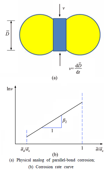
Fig. 1 Damage-rate relations for PSC model:(from Ref. [23])
During the calculations, the damage of parallel bond proceeds according to the stress condition. If the tensile stress acting on the parallel-bond periphery ( ) is less than the micro-activation stress (), the damage of parallel bond stops; if
  , the parallel bond would damage with a velocity (v), and v increases with the increment; if
  , the parallel bond would fail and be removed directly.
The PSC model parameters can be chosen to match both the static-fatigue curve (time-to-failure versus applied load) and the damage mechanisms and deformation behavior (a creep curve showing primary, secondary and tertiary creep) of Lac du Bonnet granite. However, the PSC model is not validated with physical experiment yet, especially on the study of underground opening failure behaviors. In the present work, the PSC model is utilized to produce the whole failure process around a circular opening in a jointed rock mass based on the stress corrosion mechanism. Nevertheless, due to the absence of time-dependent property measuring results for rock-like material in the laboratory experiment [15], the real values of PSC model parameters, such as  ��1 and ��2, cannot be accurately calibrated; thus these parameters were determined according to the recommendation by Ref. [23]. That is to say the temporal effect was not really considered in this work. As the first attempt to reproduce the whole failure process around circular openings by means of particle flow modeling, the numerical simulations herein still present interesting results to further understand the failure mechanism surrounding underground excavations under far field stress condition.
3 Numerical model setup and micro- parameters determination
3.1 Setup of numerical models
WONG et al [15] proposed a conceptual model to investigate the creeping damage and failure mechanism around an opening in rock-like material containing non-persistent joints in laboratory, as shown in Fig. 2. The specimens were prepared by using a mixture of barite, sand, plaster and water with a ratio of 2:4:1:1.5. The average value of unit weight, ��, is 18.27 kN/m3. The uniaxial compressive strength, ��c, elastic modulus, E, and Poisson ratio, ��, are 2.23 MPa, 0.522 GPa and 0.28, respectively. The present study referred to their modeling works, and a parametric study was undertaken to have a better understanding on the failure behaviors of rock mass around an opening with particle flow code (PFC).
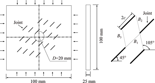
Fig. 2 Conceptual model with non-persistent joints and opening (B1, B2 and B3 are distances between joints, B1=B2=B3=10 mm [15])
PFC is a commercial software based on the principle of DEM, and with particular interest, capable to obtain predictions of rock mass failure behaviors, anisotropy, and brittleness properties that cannot be obtained using empirical methods of property estimation [24]. With PFC, three numerically analytical models, i.e., intact rock model, jointed rock model and jointed rock model with an opening, as shown in Fig. 3, were created for different purposes.
As shown in Fig. 3(a), the intact rock model which is expressed by an assembly of particles bonded with each other [25], was used to determine micro-parameters of the synthetic material. The frictionless walls around the sample were utilized as a vessel at first, and then used to simulate stress boundary. In the present study, the intact rock model was used to conduct uniaxial compression tests to calibrate intact material parameters; thus, a cylindrical sample consisted of 49035 particles with size of D=50 mm, L/D=2.0 was generated.
Figure 3(b) displays the jointed rock model with 20 non-persistent joints intersected in a 100 mm��100 mm��25 mm rectangular sample. The rectangular sample was an assembly of 73900 particles and the joints were distributed in accordance with the geometrical configuration of joints shown in Fig. 2. These joints behaved as smooth joint model, and after the joint plane was defined, a smooth joint was assigned at contacts between particles with their centers lying on the opposite sides of a joint plane. At these contacts, the bonds were removed and smooth joints were defined in a direction parallel with the joint plane. Particles intersected by a smooth joint may overlap and pass through each other rather than be forced to move around one another [26]. In PFC, a rectangle smooth joint plane cannot be created directly due to that the smooth joint contact model can only be defined on a dish-shape area with specified radius. Herein, each joint plane was obtained by geometrical combination of multiple smooth joint dishes, as displayed in Fig. 4.
After the jointed rock model was already prepared, a circular opening with the diameter of 20 mm was excavated by means of deleting the particles to simulate an underground tunnel in a non-persistent jointed rock mass,as shown in Fig. 3(c).
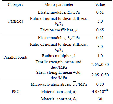
The jointed rock model with a circular opening was tested under far field stress condition, for which a typical stress path specially designed for the test procedure is displayed in Fig. 5. Note that the ��1 is applied in vertical direction, while the ��3 is applied in lateral direction, as shown in Fig. 3(c). Before the circular opening was excavated at Point B, a certain stress level was firstly achieved by movement of boundary walls. And after the circular opening was excavated, the stress level was kept unchanged all the time using a numerical servo- controlled scheme, simulating a far field loading condition, until the rock model get failed with an expected strain value as terminal criterion at Point C. To achieve the failure of the circular opening, a PSC model was applied during B�CC stage to reduce the radius of parallel bond generally according to stress corrosion mechanism. The micro-activation stress value, material constants, ��1 and ��2, for PSC model were listed in Table 1.
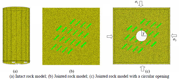
Fig. 3 Numerically simulated models:
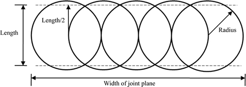
Fig. 4 Creating smooth joint plane with PFC
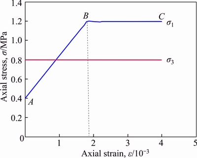
Fig. 5 A typical stress path for test
Table 1 Micro-parameter values used for intact synthetic rock material
3.2 Determination of micro-parameters for intact synthetic rock material and smooth joint
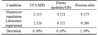
In the present paper, the numerical synthetic intact rock model is simulated by compacted particles cemented with parallel bonds. Thus, the micro- parameters for intact rock material would be classified into three categories: the first category is for particles; the second category is for parallel bonds; and the third category is for PSC model. These micro-parameters for first and second categories are determined by a ��trial and error�� process to reproduce the macroscopic mechanical properties obtained in physical experiments [5, 21], while these for the third category are determined according to the suggestions in Ref. [23]. Table 1 lists a set of micro-parameters used for the synthetic intact rock material. The minimum radius of particle is 0.65 mm and the ratio of the largest to the smallest radius of particle is chosen as 1.66. The density of the simulated rock material is 1827 kg/m3, which is the same as that obtained in laboratory [15]. Table 2 shows the comparison of macro-properties determined by numerical simulation and laboratory experiment. As can be seen from Table 2, the simulated macro-properties including UCS, elastic modulus and Poisson ratio, agree very well with that of laboratory experiment, having deviation of 0.30%, 0.19% and 2.50%, respectively.
Table 2 Comparison of intact material macro-properties determined by numerical simulation and laboratory experiment
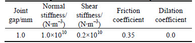
In laboratory experiment, joints were formed by inserting plane steel shims and removed before the final set of the rock-like material [12]; therefore, these joints are open with non-zero gap value. Herein, the joint gap value is 1.0 mm. Some inverse analysis were undertaken on jointed rock model (Fig. 3(b)) to choose micro- parameters for joint surface, i.e., normal stiffness, shear stiffness, friction coefficient and dilation coefficient (set to be 0.0 due to the fact that the joint surfaces in laboratory are smooth and have no asperity). Nevertheless, the simulated strength values under compression keep unchanged regardless of the variations of micro-parameters (normal stiffness, shear stiffness, friction coefficient) for joint surface, which is due to the fact that the two opposite joint surfaces cannot get interacted before peak strength when joint gap equals 1.0 mm. Consequently, these micro-parameters for joint surface are selected to be less than those of synthetic intact material in a qualitative way, as shown in Table 3.
Table 3 Micro-parameter values used for smooth joint
4 Numerical results and discussion
4.1 Progressive failure process around a circular opening in a jointed rock mass
Figure 6 shows the numerically simulated progressive failure process around a circular opening in a jointed rock mass with a lateral pressure coefficient of 2/3 (��1=1.2 MPa, ��3=0.8 MPa, which is less than the jointed rock mass strength [15]). In this figure, the red represent tensile cracks, while the blue represent shear cracks. Shortly after the opening was excavated (Fig. 6(a)), the cracks (parallel bond breakages ) initiate from the tips of pre-existing open joints. Contrary to the laboratory experiment result at this stage, in which the newly generated cracks mainly concentrated in the outer zone around the opening, the numerical simulation result shows that cracks appear in both inner zone and outer zone. That is because that the circular opening in numerical model was created through deleting the particles in one-time, while the circular opening in laboratory experiment was created by drilling slowly. The slow drilling, to some extent, protected the rock mass in the periphery of opening.
With stress corrosion, increasing cracks initiate from the rock segments among joints in the inner zone,and develop towards both the opening and the neighboring joints (see Fig. 6(b)). The excavation induces stress concentration in the Inner zone around the opening, especially in the interaction area between the joint and the opening boundary. Correspondingly, the tensile stress acting on the parallel bonds increases, and the stress corrosion works to reduce the radius of these parallel bonds in accordance with Eq. (1) in Section 2. As the stress, either tensile stress or shear stress, exceeds the corresponding strength value which has positive relationship with the parallel bond radius, the breakage of parallel bond occurs. The stress corrosion mechanism applied in the numerical simulation reproduces the failure phenomenon observed in the laboratory experiment.
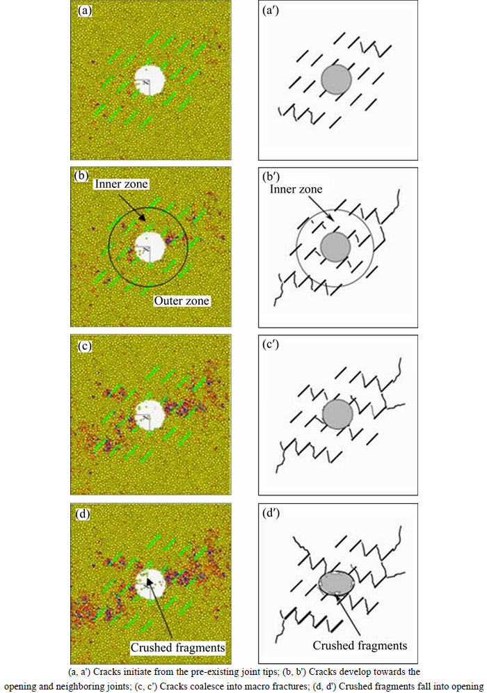
Fig. 6 Numerically simulated progressive failure process around a circular opening in a jointed rock mass (��=2/3, ��=45��, k=0.50) (Inner zone is in the region of 0
With the continuous effect of far field stress condition (��1=1.2 MPa, ��3=0.8 MPa), the micro cracks keep developing that coalesce into macro fractures, as displayed in Fig. 6(c). Basically, the fractures then expand among the joint set in a mode of step path. Fracture in the intact rock segment starts at the joint tip and propagates obliquely until it is connected with another wing fracture coming from the joint tip of a parallel system. The macro fractures become connections between neighboring joints as well as the connections between joints and the opening. Thus, the rock mass around the opening exhibits reduced strength and increased hydraulic conductivity. With increasing micro cracks appearance in the periphery of the circular opening, the surrounding rock mass become crushed, and the crushed fragments finally fall into the opening, as shown in Fig. 6(d).
Furthermore, according to Fig. 6 it could also be concluded that the failure behavior obtained from numerical simulation agrees very well with that obtained from the laboratory experiment implemented by WONG et al [15]. Therefore, the PSC model in PFC can be used to reproduce the creeping damage around a circular opening in rock-like material containing non-persistent joints. And the calibrated micro-parameters both for intact material and for smooth joint in Tables 1 and 2, respectively, are validated through the comparison of failure behaviors. On the basis of the model setup as well as the determined micro parameters, the influence of lateral pressure coefficient, joint dip angle and joint persistency on the failure behavior around a circular opening in a non-persistently jointed rock mass were further investigated numerically.
4.2 Influence of lateral pressure coefficient on failure behavior around circular opening in jointed rock mass
To investigate the influence of lateral pressure coefficient on the failure behavior around a circular opening in a non-persistently jointed rock mass, a lateral pressure of 0.4, 0.8, 1.2 and 1.6 MPa was applied on the jointed rock model with an opening (Fig. 3(c)), respectively, and the vertical stress was kept unchanged (��1=1.2 MPa). Thus, the lateral pressure coefficient of 1/3, 2/3, 1 and 4/3 was investigated correspondingly.
Figure 7 displays the numerically simulated failure patterns around a circular opening in a jointed rock mass under different lateral pressure coefficients. As shown in this figure, the failure patterns for different lateral pressure coefficients are similar to each other due to the fact that most macro fractures (coalesced by micro cracks) expand among pre-existing joints in a pattern of step path. However, some differences induced by the variation of lateral pressure coefficient can still be identified from the failure images. Specifically, at ��=1/3, the failure of intact rock material mainly happens in the lateral sides of the opening; whereas, at ��=2/3, the failure not only happens in the lateral sides but also happens in the roof. At ��=1, besides the failure in the roof and the lateral sides around the circular opening, the failure also can be found in the right corner of the floor. In addition, at ��=2/3, the failure happens in the left roof; while at ��=1, the failure happens in the right roof, and a rock block is intersected by two pre-existing open joints and a macro fracture coalesced by numerous micro cracks, which dramatically threatens the stability of underground tunnels. At ��=4/3, the failure planes mainly concentrate on the roof and the floor, intersecting the rock masses into multiple rock blocks around the opening together with the pre-existing joints. In this case, the rock mass around the opening fail in a pattern of rock block rotation. Therefore, the lateral pressure coefficient has significant influence on the failure patterns of rock mass around a circular opening. Furthermore, although most macro fractures expand among pre-existing joints in a pattern of step-path, the planar failure pattern happens as the lateral pressure coefficient increases, in which the failure propagates along a joint set and the intervening rock bridges, developing a single plane with the same dip as the joints, as shown in Figs. 7 and 8.
Note that the step-path failure and planar failure are in accordance with the tensile crack and shear crack in the laboratory experiment [15], respectively. According to Figs. 7 and 8, it is concluded that the numerical simulation agrees very well with the laboratory experiment in terms of failure patterns around the circular opening; and the failure pattern changes from step-path failure to planar failure and block rotation failure with the increment of lateral pressure coefficient.
In order to further understand the influence of lateral pressure coefficient on the failure behavior around a circular opening in a non-persistently jointed rock mass,the micro crack (tensile + shear) evolution with timestep in both inner zone and outer zone were investigated. Figure 9 displays the numerically simulated crack evolution with timestep around the opening under different lateral pressure coefficients. Note that the crack number is expressed as the cracks per unit volume (cm3), and the higher crack number indicates the higher extent of intact rock mass failure.
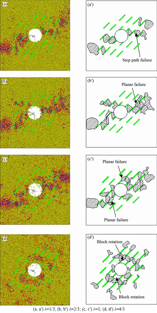
Fig. 7 Numerically simulated failure patterns around a circular opening in a jointed rock mass under different lateral pressure coefficients (The yellow and green imply the intact material and joints, respectively; the red and blue imply the tensile cracks and shear cracks, respectively):
As shown in Fig. 9, the lateral pressure coefficient has great influence on the crack evolution in both of inner zone and outer zone, and the crack number in inner zone is larger than that in outer zone. At ��=1/3 (Fig. 9(a)), in the inner zone, the crack number increases significantly after the opening excavation (from 50��103 to 170��103 timestep, Phase 1), which is mainly due to the release of original stress around the opening. Afterwards, the increase rate of crack number stays general from 170��103 to 400��103 timestep (Phase 2). In this phase, the generation of crack (bond breakage) is induced by the stress corrosion; otherwise, the crack would not appear further after the former phase. Around the 400��103 timestep, a significant increase of crack number happens (Phase 3). Since then, the opening collapses and the whole model fails. On the contrary, in the outer zone, the release of original stress in Phase 1 has negligible effect on the crack generation. The increase rate in Phase 1 in outer zone is similar to that in Phase 2. The crack number in outer zone increases generally until the model fails.
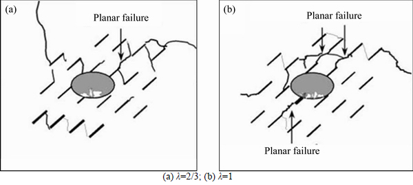
Fig. 8 Laboratory experimental failure patterns around circular opening in jointed rock mass under different lateral pressure coefficients [15]:
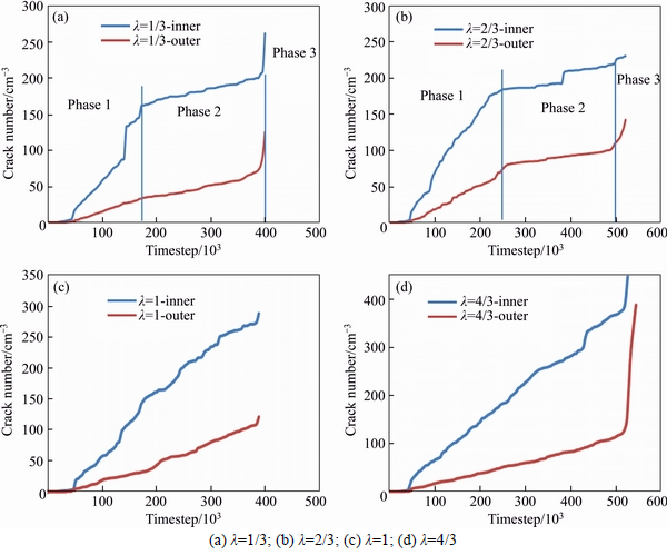
Fig. 9 Numerically simulated crack evolution with timestep in inner zone and outer zone under different lateral pressure coefficients:
At ��=2/3 (Fig. 9(b)), in the inner zone, the crack number with timestep curve also experiences three phases. Compared to the crack number with timestep curve at ��=1/3, the Phase 1 at ��=2/3 last more timesteps because of the higher confining stress. Then, in Phase 2 the crack number increases slowly until the rock model fails due to the stress corrosion. Moreover, the crack number with timestep curve in the outer zone displays obvious three phases. That is because the release of the higher original stress influences the status of the rock mass induced by the excavation (Phase 1). Then in Phase 2 in the outer zone, the stress corrosion mechanism works to reduce the parallel bond strength between particles and makes the bonds fail finally. With the accumulation of cracks in inner and outer zones, the rock model gets failed (Phase 3).
As can be seen from Figs. 9 (c) and (d), the crack number increases significantly after the excavation until rock model fails when the lateral pressure coefficient increases to 1 and 4/3. The phases in the curves cannot be obviously observed. That is because, due to the higher original stress, the stress corrosion in Phase 2 becomes as dominant as the original stress release in Phase 1 to induce parallel bond breakage. Thus, the crack number before the rock model fail at ��=1 and 4/3 is larger than that at ��=1/3 and 2/3. As observed in the laboratory experiment [12], the strain in inner and outer zones increased with the lateral pressure coefficient. Correspondingly, in the present study, the crack number also increases with the lateral pressure coefficient, as shown in Fig. 9.
In summary, the increase of lateral pressure coefficient aggravates the failure around the circular opening. In underground engineering, with the increase of excavation depth, the original stress (especially the lateral pressure) would increase; thus extra support measures need to be applied to maintain the underground opening stable.
4.3 Influence of joint dip angle on failure behavior around a circular opening in a jointed rock mass
To better understand the influence of joint orientation on the failure behavior around a circular opening, the rock model having different joint dip angle was investigated. The dip angle, ��, varies from 15�� to 60�� with an interval of 15��, and the lateral pressure coefficient keeps constant (��=2/3, i.e., ��1=1.2 MPa, ��3=0.8 MPa). Figure 10 displays the numerically simulated failure patterns around a circular opening in a jointed rock mass having different dip angles. According to this figure, the step-path failure pattern dominantly occurs to the jointed rock models regardless of the joint dip angle, even though the block rotation failure pattern happens to the rock model at ��=15�� and the planar failure pattern happens to the rock model at ��=45��. However, the failure location varies with the joint dip angle. In particular, at ��=15��, the failures mainly locate at the lateral side of the circular opening, and several rotated rock blocks are generated with the interaction of failure planes and pre-exited joints. At ��=30��, although the failures locate at the lateral side of the circular opening, there are few rock blocks generated beside. When the joint dip angle increases to 45�� and 60��, besides the failures locating at the sides of the opening, there are failures generated at the corners of roof, which threaten dramatically the safety and stability of the opening.
Figure 11 displays the numerically simulated crack number evolution with timestep around a circular opening in a jointed rock mass having different joint dip angles. As shown in Figs. 11 (a) and (b), when the joint dip angle is low (��=15�� and 30��), the crack number, in both inner and outer zones, increases significantly with a relatively constant rate after the excavation until the opening collapses and rock model fails. There is no obvious phase observed in the curve of crack number evolution, and the crack number right before the model fails is relatively low (approximately 175 cm�C3 in inner zone, and 75 cm�C3 in outer zone). That is because, at low dip angle, the stress mainly concentrate on the joint tips, and the failure plane initiates from one joint tip and develops to another joint tip.
On the contrary, when the joint dip angle is high (��=15�� and 30��), as shown in Figs. 11 (c) and (d), there are three phases in the crack number evolution curve. That is to say, after the phase of original stress release the stress corrosion works dominantly for timesteps to make the opening collapse finally. There are more cracks in both inner and outer zones (e.g., about 275 cracks/cm3 in inner zone and 100 cm�C3 in outer zone at ��=60��) than that at low dip angle, due to the fact that the stress mainly concentrate on the intact material between joints, which induces more intact material failures.
To sum up, with the increment of joint dip angle more failures locate at the roof of the opening and more cracks generate in both inner and outer zones.
4.4 Influence of joint persistency on failure behavior around a circular opening in a jointed rock mass
In order to investigate the influence of joint persistency on the failure behavior around a circular opening in a rock mass having non-persistent joints, different rock models having various joint persistence degrees (k=0.0, 0.25, 0.50 and 0.75) were simulated using particle flow modeling method. The joint dip angle keeps 45��, and the lateral pressure coefficient maintains 2/3. Figures 12 and 13 display the numerically simulated failure patterns and crack number evolution around a circular opening in a jointed rock mass having different joint persistency.
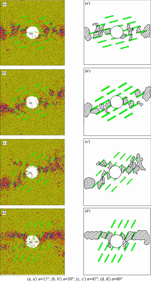
Fig. 10 Numerically simulated failure patterns around a circular opening in a jointed rock mass having different dip angles (The yellow and green imply the intact material and joints, respectively; the red and blue imply the tensile cracks and shear cracks, respectively):
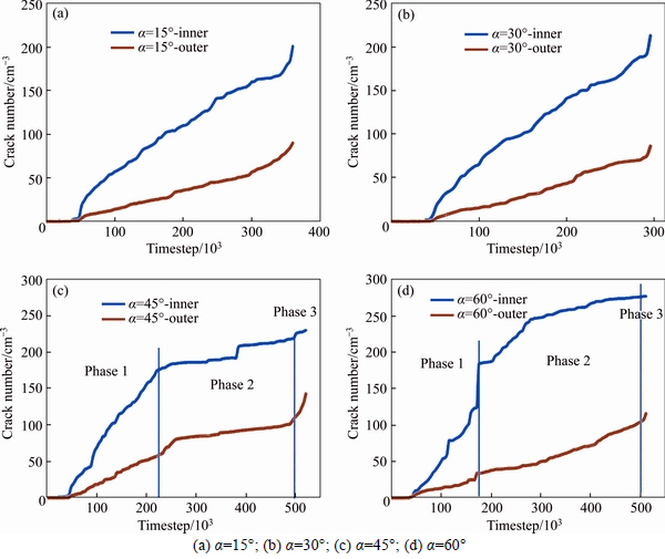
Fig. 11 Numerically simulated crack number evolution with timestep around a circular opening in a jointed rock mass having different joint dip angle:
At k=0.0, there are notches generated near the circular opening (Fig. 12(a)) due to the original stress release as well as the stress corrosion, which agrees very well with the observation of failure around a circular test tunnel [28, 29]. As the joint persistency increases to 0.25, besides the generated notch near the opening, the failures distribute more extensively along the pre-existed joints (Fig. 12(b)). With the further increment of joint persistency, there are more failures around the opening (Fig. 12(c)), and even a few rotated rock blocks are generated (Fig. 12(d)).
In accordance with Fig. 13, the crack number in the inner zone decreases with the increment of joint persistency. The pre-existed joints around the opening already break the rock mass, and the newly generated failure planes easily coalesce with the joints having larger persistence degree to induce the opening collapse.
5 Conclusions
1) The failure behavior around the circular opening observed in laboratory experiment was reproduced successfully based on the determined particle parameters, parallel bond parameters, and PSC parameters.
2) Three failure patterns identified were step path failure, planar failure and block rotation, which depend on the lateral pressure coefficient. The increment of lateral pressure coefficient aggravates the failure around the circular opening.
3) At low dip angle, failures around the opening initiate from one joint tip, and then develop to another joint tip; while at high dip angle, stress concentrate on the intact material between joints, which induce significant failure of intact material.
4) Even though larger joint persistency produced less cracks around the circular opening, the rock models with larger joint persistency generate more extensively distributed cracks and rotated rock blocks to induce instability of the opening.
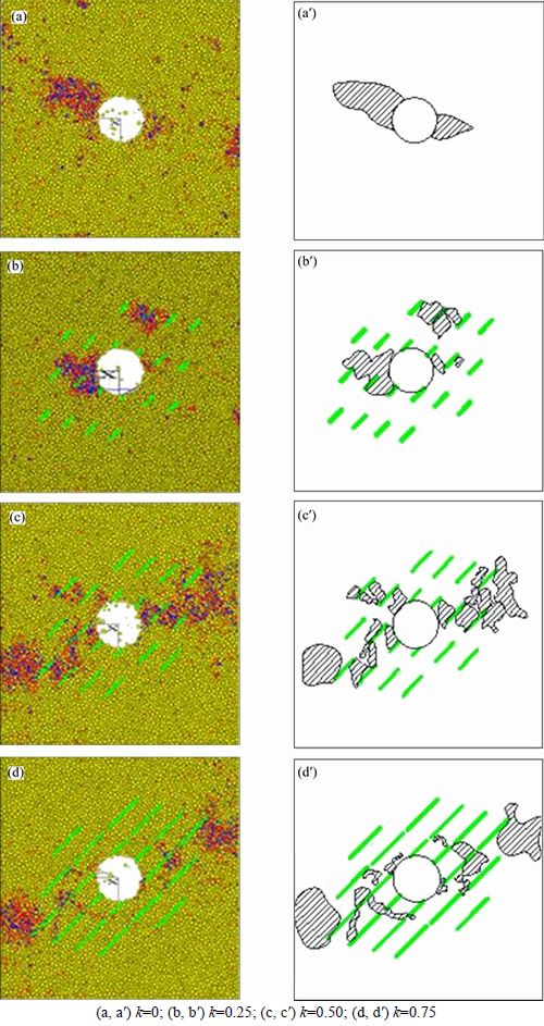
Fig. 12 Numerically simulated failure patterns around a circular opening in a jointed rock mass with different joint persistency (The yellow and green imply the intact material and joints, respectively; the red and blue imply the tensile cracks and shear cracks, respectively):
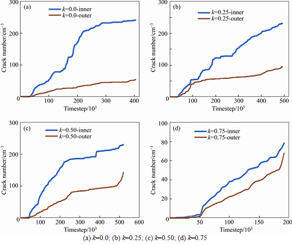
Fig. 13 Numerically simulated crack evolution with timestep around a circular opening in a jointed rock mass having different joint persistency:
References
[1] KULATILAKE P H S W, MALAMA B, WANG J L. Physical and particle flow modeling of jointed rock block behavior under uniaxial loading [J]. International Journal of Rock Mechanics and Mining Science, 2001, 38(5): 641�C657.
[2] JIANG Q, FENG X T, HATZOR Y H, HAO X J, LI S J. Mechanical anisotropy of columnar jointed basalts: An example from the Baihetan hydropower station, China [J]. Engineering Geology, 2014, 175: 35�C45.
[3] FORTSAKIS P, NIKAS K, MARINOS V, MARINOS P. Anisotropic behavior of stratified rock masses in tunneling [J]. Engineering Geology, 2012, 141�C142: 74�C83.
[4] KIM B H, KAISER P K, GRASSELLI G. Influence of persistence on behavior of fractured rock masses [J]. Geological Society, London, Special Publications, 2007, 284: 161�C173.
[5] YANG X X, KULATILAKE P H S W, CHEN X, JING H W, YANG S Q. Particle flow modeling of rock blocks with non-persistent open joints under uniaxial compression [J]. International Journal of Geomechanics, 2016, 16(6): 04016020.
[6] LAJTAI E Z, LAJTAI V N. The collapse of cavities [J]. International Journal of Rock Mechanics and Mining Science, 1975, 12: 81�C86.
[7] LAJTAI E Z, CARTER B J, DUNCAN E J S. En echelon crack-arrays in potash salt rock [J]. Rock Mechanics and Rock Engineering, 1994, 27(2): 89�C111.
[8] SAGONG M, PARK D, YOO J, LEE J S. Experimental and numerical analyses of an opening in a jointed rock mass under biaxial compression [J]. International Journal of Rock Mechanics and Mining Science, 2011, 48(7): 1055�C1067.
[9] WANG S Y, Sloan S W, Tang C A, Zhu W C. Numerical simulation of the failure mechanism of circular tunnels in transversely isotropic rock masses [J]. Tunnelling and Underground Space Technology, 2012, 32: 231�C244.
[10] Wang T T, Huang T H. Anisotropic deformation of a circular tunnel excavated in a rock mass containing sets of ubiquitous joints: Theory analysis and numerical modeling [J]. Rock Mechanics and Rock Engineering, 2014, 47(2): 643�C657.
[11] Fakhimi A, Carvalho F, Ishida T, Labuz J F. Simulation of failure around a circular opening in rock [J]. International Journal of Rock Mechanics and Mining Science, 2002, 39: 507�C515.
[12] LIN P, WONG R H C, Tang C A. Experimental study of coalescence mechanism and failure under uniaxial compression of granite containing multiple holes [J]. International Journal of Rock Mechanics and Mining Science, 2015, 77: 313�C327.
[13] Wong R H C, LIN P. Numerical study of stress distribution and crack coalescence mechanisms of a solid containing multiple holes [J]. International Journal of Rock Mechanics and Mining Science, 2015, 79: 41�C54.
[14] Jia P, Tang C A. Numerical study on failure mechanism of tunnel in jointed rock mass [J]. Tunnelling Underground Space Technology, 2008, 23(5): 500�C507.
[15] Wong R H C, LIN P, YU Z X, Tang C A, CHAU K T. Creeping damage around an opening in rock-like material containing non- persistent joints [J]. Engineering Fracture Mechanics, 2002, 69(17): 2015�C2027.
[16] Yang S Q, Huang Y H, Jing H W, LIU X R. Discrete element modeling on fracture coalescence behavior of red sandstone containing two unparallel fissures under uniaxial compression [J]. Engineering Geology, 2014, 178: 24�C48.
[17] Ding X B, Zhang L Y. A new contact model to improve the simulated ratio of unconfined compressive strength to tensile strength in bonded particle models [J]. International Journal of Rock Mechanics and Mining Science, 2014, 69: 111�C119.
[18] Zhang Y, Stead D. Modeling 3D crack propagation in hard rock pillars using a synthetic rock mass approach [J]. International Journal of Rock Mechanics and Mining Science, 2014, 72: 199�C213.
[19] Bahaaddini M, Sharrock G, Hebblewhite B K. Numerical investigation of the effect of joint geometrical parameters on the mechanical properties of a non-persistent jointed rock mass under uniaxial compression [J]. Computers and Geotechnics, 2013, 49: 206�C225.
[20] FAN Xiang, Kulatilake P H S W, CHEN Xin, CAO Ping. Crack initiation stress and strain of jointed rock containing multi-cracks under uniaxial compressive loading: A particle flow code approach [J]. Journal of Central South University, 2015, 22: 638�C645.
[21] YANG Xu-xu, Kulatilake P H S W, JING Hong-wen, YANG Sheng-qi. Numerical simulation of a jointed rock block mechanical behavior adjacent to an underground excavation and comparison with physical model test results [J]. Tunnelling and Underground Space Technology, 2015, 50: 129�C142.
[22] Chen W, Konietzky H, Muntazir Abbas S. Numerical simulation of time-independent and dependent fracturing in sandstone [J]. Engineering Geology, 2015, 193: 118�C131.
[23] Potyondy D O. Simulating stress corrosion with a bonded- particle model for rock [J]. International Journal of Rock Mechanics and Mining Science, 2007, 44: 677�C691.
[24] Mas Ivars D, Pierce M E, Darcel C, Reyes-Montes J, Potyondy D O, Young R P, CUNDALL P A. The synthetic rock mass approach for jointed rock mass modeling [J]. International Journal of Rock Mechanics and Mining Science, 2011, 48(2): 219�C244.
[25] Itasca Consulting Group Inc. PFC3D manual, version 4.0 [R]. Minneapolis, Minnesota, 2008.
[26] Pierce M, Cundall P, Potyondy D O, Mas Ivars D. A synthetic rock mass model for jointed rock [C]// Rock Mechanics: Meeting Society's Challenges and Demands, 1st Canada-US Rock Mechanics Symposium. London: Vancouver, 2007��341�C349.
[27] Hoek E, Brown E T. Underground excavations in rock [M]. London��Institution of Mining and Metallurgy, 1980.
[28] Martin C D, Read R S, Martino J B. Observations of brittle failure around a circular test tunnel [J]. International Journal of Rock Mechanics and Mining Science, 1997, 34(7): 1063�C1073.
[29] Potyondy D O, Cundall P A. A bonded-particle model for rock [J]. International Journal of Rock Mechanics and Mining Science, 2004, 41: 1329�C1364.
(Edited by HE Yun-bin)
Cite this article as: YANG Xu-xu, JING Hong-wen, CHEN Kun-fu, YANG Sheng-qi. Failure behavior around a circular opening in a rock mass with non-persistent joints: A parallel-bond stress corrosion approach [J]. Journal of Central South University, 2017, 24(10): 2406�C2420. DOI:https://doi.org/10.1007/s11771-017-3652-0.
Foundation item: Project (2013CB036003) supported by the National Basic Research Program of China��Projects (51374198, 51134001, 51404255) supported by the National Natural Science Foundation of China; Project(BK20150005) supported by the Natural Science Foundation of Jiangsu Province for Distinguished Youth Scholar, China
Received date: 2015-11-16; Accepted date: 2016-03-25
Corresponding author: JING Hong-wen, Professor; Tel: +86�C13869899028; E-mail: hongwen_jing@hotmail.com

