
J. Cent. South Univ. (2020) 27: 2945-2958
DOI: https://doi.org/10.1007/s11771-020-4520-x

Mechanical properties and failure behavior of rock with different flaw inclinations under coupled static and dynamic loads
XIAO Peng(肖鹏)1, LI Di-yuan(李地元)1, ZHAO Guo-yan(赵国彦)1, ZHU Quan-qi(朱泉企)1,LIU Huan-xin(刘焕新)2, ZHANG Chun-shun(张春顺)3
1. School of Resources and Safety Engineering, Central South University, Changsha 410083, China;
2. Deep Mining Laboratory of Shandong Gold Group, Laizhou 261442, China;
3. Department of Civil Engineering, Monash University, Clayton, VIC 3800, Australia
 Central South University Press and Springer-Verlag GmbH Germany, part of Springer Nature 2020
Abstract: The deep fissured rock mass is affected by coupled effects of initial ground stress and external dynamic disturbance. In order to study the effect of internal flaw on pre-stressed rock mechanical responses and failure behavior under impact loading, intact granite specimens and specimens with different flaw inclinations are tested by a modified split Hopkinson pressure bar (SHPB) and digital image correlation (DIC) method. The results show that peak strain and dynamic strength of intact specimens and specimens with different flaw angles (α) decrease with the increase of axial static pressure. The 90° flaw has weak reduction effect on peak strain, dynamic strength and combined strength, while 45° and 0° flaws have remarkable reduction effect. Specimens with 90° flaw are suffered combined shear and tensile failure under middle and low axial static pre-stresses, and suffered shear failure under high axial static pre-stresses. Specimens with 45° and 0° flaws are suffered oblique shear failure caused by pre-existing flaw under different axial static pre-stresses. Besides, based on digital image correlation method, it is found that micro-cracks before formation of macro fractures (include shear and tensile fractures) belong to tensile cracks. Tensile and shear strain localizations at pre-existing flaw tip for specimen with 45° and 0° flaws are produced much earlier than that at other positions.
Key words: split Hopkinson pressure bar (SHPB) system; digital image correlation (DIC); coupled static and dynamic loads; flaw; crack propagation
Cite this article as: XIAO Peng, LI Di-yuan, ZHAO Guo-yan, ZHU Quan-qi, LIU Huan-xin, ZHANG Chun-shun. Mechanical properties and failure behavior of rock with different flaw inclinations under coupled static and dynamic loads [J]. Journal of Central South University, 2020, 27(10): 2945-2958. DOI: https://doi.org/10.1007/s11771-020- 4520-x.
1 Introduction
With development of industrial technology and consumption of surface resources, human beings are increasingly exploiting underground resources. The deep underground engineering such as tunnels and hydro power stations is subjected to high ground stress, and often subjected to dynamic loads such as mechanical disturbance and blasting. Stability of deep engineering has always been a concern, which is closely related to work environment of underground workers and equipments. It is found that rock masses at depth have different failure phenomena with shallow rock masses under traditional static and dynamic loads [1, 2]. Some scholars believe that the phenomenon is caused by the combination effect of high ground stress and impact load [3]. Due to the different failure mode caused by static and dynamic loads, some studies have been carried out on engineering materials under coupled static and dynamic loading [4-9]. The coupled static and dynamic loading system based on modification of splitting Hopkinson pressure bar system was developed by LI et al [10]. ZHOU et al [11] carried out the Brazilian disc test under the coupled static and dynamic loads and found that tensile strength of granite decreased with the increase of static pre- stress. TAO et al [12] studied stress concentration around a cavity of rock specimen caused by combined static load and stress wave. Higher pre- static load is more likely to cause specimen with a cavity damage. LI et al [13] discovered and explained the transition behavior from tensile failure to shear failure of intact green sandstone specimen under coupled static and dynamic loading. The effects of internal hole on mechanical parameters and failure mode were also studied in detail.
Besides, engineering materials (such as rock and concrete) in tunnels and underground powerhouses often contain defects caused by natural or human activities. A number of studies have shown that the destruction of brittle materials usually initiates from their original defects. For this reason, scholars carried out a number of researches on brittle materials with different flaw angles and various flaw or hole shapes [14-19]. WONG et al [20] studied granite with different diameters of single hole under uniaxial compression by experiments and numerical simulation. The effects of specimen diameter and hole size on strength and failure process of specimen were obtained. LI et al [21] studied mechanical properties and failure process of marble specimen with different flaw angles and lengths under impact loading. The effects of flaw angles and flaw lengths on dynamic strength of marble specimens were obtained. It was found that tensile failure occurred in intact specimen, but shear failure occurred in flawed specimen under impact loading.
As shown in Figure 1, deep rock engineering often contains flaws and is subjected to a combination of high ground stress, blasting and other dynamic loads. Up to now, there are few studies to investigate mechanical properties of rock with defects under coupled static and dynamic loads [22-24]. Therefore, this paper intends to study failure behavior of rock with flaw under coupled static and dynamic loads. Besides, digital image correlation (DIC) method is used to analyze strain field of specimen during dynamic failure process. As a non-contact deformation measurement method, DIC technology can accurately analyze deformation and failure process of rock specimens under static and dynamic loading [25-28].
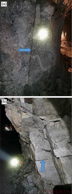
Figure 1 Rock flaws in deep mine roadway
2 Test system and specimen preparation
2.1 Testing machine
As shown in Figure 2, the test is carried out on modified split Hopkinson pressure bar (SHPB). The test machine includes dynamic impact components and static load device. Elastic modulus of bar is 240 GPa. P-wave velocity is 5400 m/s. Density is 7800 kg/m3.

Figure 2 (a) Sketch of modified SHPB system for coupled axial static and dynamic loading; (b) Photo of testing system and DIC equipment modified from Refs. [29, 30]
After adjusting test machine, tested specimen is placed between incident bar and transmitted bar. Static load is applied to specimen through an axial static pressure component at end, and then the air valve is opened to accelerate striker with high pressure air. Striker impacts incident bar to form an incident wave. After incident wave reaches specimen, it is subjected to multiple transmission and reflection on both end faces of specimen. A transmitted wave and a reflected wave are formed in transmitted and incident bars, and specimen is destroyed during the effect of stress wave. Stress wave data are recorded by strain gauges and super-dynamic strain meter.
Besides, DIC technique is applied to record and analyze deformation and fracturing process of specimen. Firstly, white paint is sprayed on surface of specimen and then black speckle is brushed. Failure evolution process of specimen is captured by a high speed camera (Phantom V711). Finally, speckle displacement change of specimen surface is analyzed by commercial software (Vic-2D 6.0) to determine the evolution of strain field of specimen surface. The videography frequency is 79161 fps and it means that each picture is taken 12.6 ms-1.
Dynamic mechanical parameters of specimens can be calculated, such as dynamic stress and average dynamic strain rate according to stress wave balance as shown in Eq. (1) [31, 32]:
 (1)
(1)
where σI(t) is the incident stress; σR(t) is the reflection stress; σT(t) is the transmitted stress; ρeCe represent the bar’s wave impedance; Ls represent the specimen’s length; t represents the duration; Aε represent the bar’s cross-sectional area; As represent the specimen’s cross-sectional area.
2.2 Testing specimens
The granite specimen is from Changtai County, Fujian Province, China. Elastic modulus of specimen, density, Poisson ratio, wave velocity and uniaxial compressive strength (UCS) are 40.71 GPa, 2790.3 kg/m3, 0.23, 5345.4 m/s and 183.9 MPa, respectively.
The granite was analyzed with a petrographic microscope under polarization light and cross polarization light. The main mineral composition includes plagioclase (65%), quartz (18%), biotite (8%), pyroxene (5%), hornblende (3%) and opaque minerals (1%), as shown in Figure 3. The granite is fine-grained with holocrystalline texture and massive structure.
As shown in Figure 4, the dimensions of specimen is 45 mm×45 mm×20 mm (width× height×thickness). The angle α between normal line of flaw and loading direction is taken as flaw angle. There are four types of specimens, namely intact specimen, specimen with 90° flaw, specimen with 45° flaw, and specimen with 0° flaw. The artificial flaw is located at the center of specimen and it has a length of 10 mm and a width of 1 mm.
The static loads are 18.4, 55.2, 92.0 and 128.7 MPa, respectively. These static loads equal 10%, 30%, 50% and 70% of UCS, respectively. One type specimen consists of 4 groups. A, B, C and D represent 10%, 30%, 50% and 70% of UCS, respectively. B-int-2 is the second specimen of intact specimen under 30% UCS static load. C-90°-3 is the third specimen of specimen with 90°flaw under 50% UCS static load.

Figure 3 Micrograph of mineral composition (P1―Plagioclase; Q―Quartz; Bt―Biotite; Px―Pyroxene; Hbl―Hornblende )
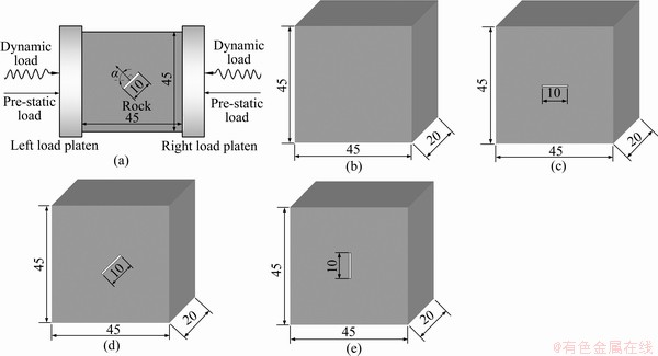
Figure 4 (a) Specimen loading diagram; Definition of flaw angle:(b) Intact specimen;(c) 90° flaw; (d) 45° flaw;(e) 0° flaw (unit: mm)
Figure 5 shows stress curves of specimen B-int-1. σT(t) coincides with σI(t)+σR(t), which indicates that the stress equilibrium state is reached.
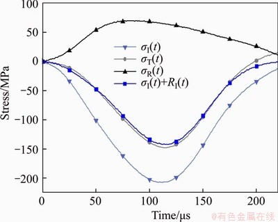
Figure 5 Typical stress curve of specimen B-int-1
3 Experimental results and analysis
3.1 Testing results
Strength of specimens under coupled axial static and dynamic loads can be obtained by Eq. (1) and strain rates of specimens are between 48-93 s-1, which can be regarded as a constant strain rate range. Combined strength equals static load plus dynamic strength, which can be expressed as:
 (2)
(2)
where σcs represents the combined strength; σas represents the static load; σd represents the dynamic strength. The testing results are listed in Table 1.
3.2 Dynamic stress-strain curves
Dynamic stress-strain curves of four types specimens under different axial static pressure are shown in Figure 6. With the increase of axial static pressure from 18.4 to 128.7 MPa, the peak stress and peak strain of four types of specimens are decreased. The post peak curves of specimens with a flaw have good consistency under different axial static pressures. When the axial static stress is 55.2 MPa, the stress-strain curve rebounds, as shown in Figure 6(a). This phenomenon indicates that the specimen absorbs excessive impact energy, thereby releasing energy in the form of curve rebound.
3.3 Dynamic and combined strengths
Dynamic strength and combined strength of four types of specimens under different axial static pressures are shown in Table 2 and Figures 7 and 8. Dynamic strength of four types of specimens decreases with the increase of axial static pressure. Combined strength of intact specimen and specimen with 90° flaw decreases firstly and then increases slowly, and the minimum value is obtained at 30% of UCS. Combined strength of specimens with 45° and 0° flaws increases gently.
Besides, flaw results in a significant reduction of dynamic strength and combined strength of specimens. When axial static pressure is 10% of UCS, dynamic strength of specimen with 90° flaw, 45° flaw, and 0° flaw is 5%, 36%, 42% lower than that of intact specimen, respectively. When axial static pressure is 70% of UCS, dynamic strength of specimen with 90° flaw, 45° flaw, and 0° flaw is 11%, 33%, 47% lower than that of intact specimen, respectively. When flaw angle is changed from 90°to 45°, dynamic strength of specimen is greatly reduced. Correspondingly, similar variation trend can be observed for combined strength of specimens.
It indicates that 90° flaw has weak effect on dynamic strength and combined strength, while 45° and 0° flaws have strong influence on dynamic strength and combined strength of rock under different axial static pressures.
Compressive stress wave can basically pass through specimen with 90° flaw, therefore 90° flaw has weak effect on strength. Part of stress wave will be blocked to form tensile wave at flaw for 45° flaw, which obviously reduces strength of specimen. More stress waves turn into tensile wave for 0°flaw, so 0°flaw has the greatest effect on strength.
3.4 Dynamic elastic modulus
Dynamic elastic modulus is the slope of the straight line on stress-strain curve. The relation between dynamic elastic modulus and axial static stress is shown in Figure 9.
Dynamic elastic modulus of intact specimen and specimen with a 90° flaw increases with the increase of axial static pressure. Elastic modulus of specimen with 45° flaw or 0° flaw increases first and decreases afterwards, and the maximum elastic modulus is obtained at 50% of UCS. On the other hand, 45°and 0°flaws reduce elastic modulus.
At low and medium axial pressures, 90° flaw increases dynamic elastic modulus due to the more obvious compaction effect on specimen under the same axial pressure. 45°flaw makes part of compressive stress wave become tensile wave, resulting in lower impact resistance of specimen at the same strain. 0° flaw results in a larger tensile wave and therefore has a greater effect.
Table 1 Sizes and strength of granite specimens
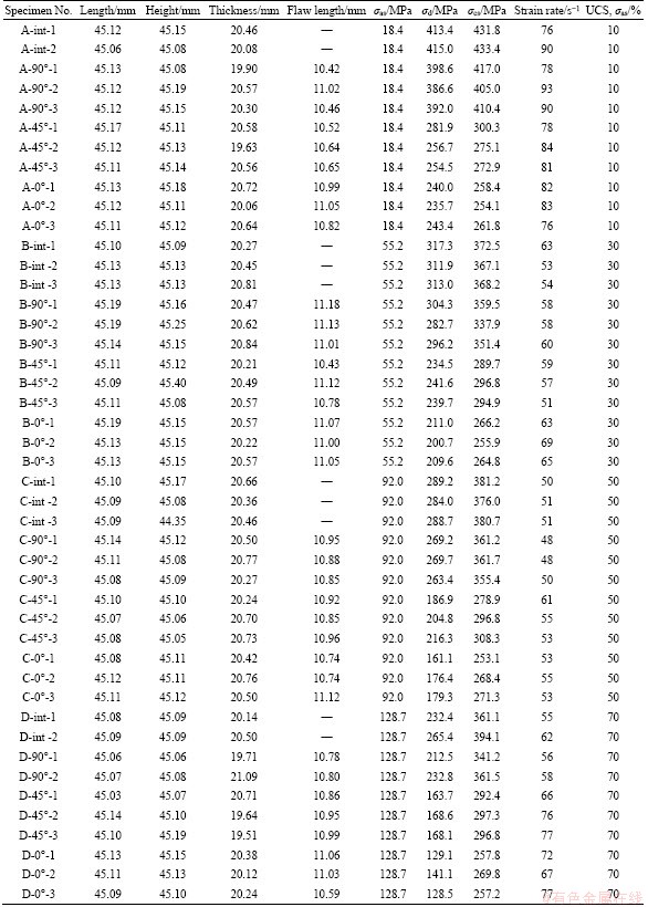
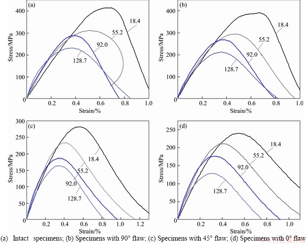
Figure 6 Dynamic stress-strain relationship under different axial static pressures of:
Table 2 Average strength of specimens in each group

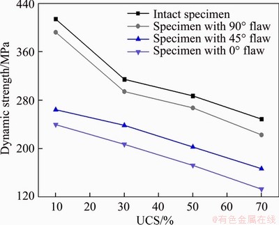
Figure 7 Change of dynamic strength with axial static stress
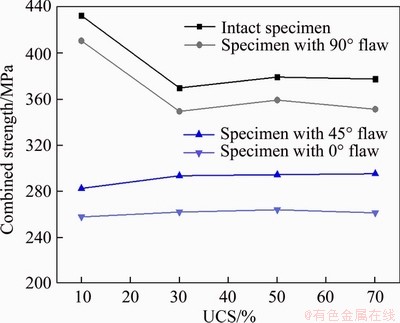
Figure 8 Change of combined strength with axial static pressure
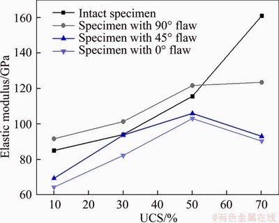
Figure 9 Change of dynamic elasticity modulus with axial static pressure
3.5 Peak strains
The corresponding dynamic strain at peak stress is defined as peak strain of specimen. The relation between peak strain and axial static stress is shown in Figure 10.
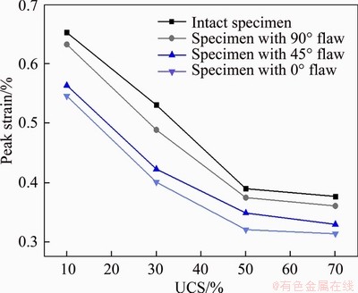
Figure 10 Change of peak strain with axial static pressure
Peak strains of four types of specimens decrease rapidly with the increase of axial static pressure. The existing of artificial flaw will reduce peak strain of specimen, and effect of 0° flaw on peak strain is the most remarkable. The sum of static strain and dynamic strain for the same type of specimen is approximately a fixed value under coupled static and dynamic loading [13]. When axial pressure increases, static strain will also increase, which will lead to reduction of dynamic strain for four types of specimens.
The total strain of specimen with flaw is lower than that of intact specimen, because specimen with flaw is more likely to be damaged than intact specimen. Besides, static strain of specimen with a flaw is bigger than that of intact specimen under the same axial pressure. Therefore, dynamic strain of flawed specimen will be lower than that of intact specimen.
4 Dynamic crack initiation and propagation
DIC device is used to record and analyze crack initiation and propagation process for specimens. The maximum principal strain field evolution of four types of specimens is shown in Figures 11-14. A large value (scales on right tab) indicates that the strain generated at this position is large. Based on strain evolution contours, dynamic crack initiation and crack types can be identified.
4.1 Intact specimens
The maximum principal strain field evolution of intact specimens under different axial static pressures is shown in Figure 11. Micro- cracks appear by step in upper and lower parts of specimen A-int-3, and then develop as axial splitting tensile fractures. Micro-cracks appear by step in upper, lower and middle parts of specimen B-int-1, and then develop into axial splitting tensile fractures. Micro-cracks appear by step in upper and lower parts of specimen C-int-1, and then develop into axial splitting tensile fractures and also shear fractures. Micro-cracks appear in upper, lower and middle parts of specimen D-int-1, and then develop into shear fractures.
Based on the above observations, it can be found that axial splitting tensile failure occurs in specimens with 10% and 30% of UCS axial static pressure. Combined tensile and shear failures occur in specimen with 50% of UCS axial static pressure. However, when axial static pressure reaches 70% of UCS, shear failure dominates failure process of intact granite specimen. The conclusion is consistent with the former research result in Ref. [13].
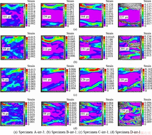
Figure 11 Max-principal strain field evolution of intact specimens under different static loads:
4.2 Specimen with 90° flaw
The maximum principal strain field evolution of specimens with 90° flaw under different axial static pressures is shown in Figure 12. Four micro-cracks appear by step in the middle, upper and lower part of specimen A-90°-1, where two micro-cracks are in the middle part, and then develop into two shear fractures and two tensile fractures. Three micro-cracks appear by step in lower left, upper left and lower right part of specimen B-90°-2, and then develop into two shear fractures and one tensile fracture. Three micro-cracks form by step in middle, above and below part of specimen C-90°-2, and then develop into one shear fracture and two tensile fractures. Three micro-cracks form in middle, above and below parts of specimen D-90°-3, and then develop into three shear fractures.
It can be concluded that specimen with 90° flaw is suffered combined shear and tensile failure under axial static pressure between 10% and 50% of UCS, and suffered shear failure when axial static pressure is 70% of UCS.
4.3 Specimen with 45°flaw
The maximum principal strain field evolution of specimens with 45° flaw under different axial static pressures is shown in Figure 13. Strain field evolution feature of specimens with 45° flaw is very similar under different axial pressures. Tip of flaw all generates micro-cracks first, which then develop as oblique shearing macro-cracks, accompanied by generation of other micro-cracks. Specimen eventually undergoes oblique shear failure caused by pre-existing flaw.
According to Ref.[21], quasi-coplanar shear cracks first appear at flaw tip for specimens with 45°flaw under impact loading. However, the opposite is that oblique shear cracks first appear at 45° flaw tip under coupled static and dynamic loads. This may be related to static pressure constraint at the end of the specimen.

Figure 12 Max-principal strain fields evolution of specimens with 90°flaw under different static loads:
4.4 Specimen with 0° flaw
The maximum principal strain field evolution of specimens with 0° flaw under different axial static pressures is shown in Figure 14.
Strain field evolution feature of specimens with 0° flaw is also very similar under different axial pressures. Micro-cracks occur symmetrically at tip of flaw, and then the development directions change to form two shear fractures. When shear fractures are formed, other micro-cracks generate at edge of specimen. Eventually, specimen is mainly subjected to oblique shear failure caused by pre-existing flaw.
4.5 Identification of micro-crack types inside macro fractures
In order to identify micro-crack types, three key points (flaw tip, the center and end of macro fracture) are selected to monitor tensile and shear strain evolution for each type of granite specimen. Tensile and shear strain evolutions at each point are shown in Figures 15 (a)-(c) during dynamic impact process. The following results can be obtained:
1) The tensile strain is much larger than the corresponding shear strain at each point, which indicates that the micro-cracks inside macro fractures (include shear and tensile fractures) belong to tensile micro-cracks.
2) The tensile and shear strain produced at the pre-existing flaw tips (P1 in Figure 15) for specimens with 45°and 0°flaw are much earlier than that at other positions.

Figure 13 Max-principal strain fields evolution of specimens with 45° flaw under different static loads:
3) The micro-crack generation speed of the specimen with 0° flaw is the fastest, and the specimen with 45° flaw is the second, while the specimen with 90° flaw and the intact specimen are the lowest.
5 Conclusions
Intact granite specimens and specimens with different flaw directions are tested by using modified split Hopkinson pressure bar and digital image correlation method. Main conclusions are listed as follows:
1) Peak strain and dynamic strength of intact specimens and specimens with the flaw decrease with the increase of axial static pressure. The internal flaw reduces peak strain, dynamic strength and combined strength of specimen. 90° flaw has the smallest reduction effect on peak strain, dynamic strength and combined strength, while 45° and 0° flaws have remarkable reduction effect.
2) Under impact loading, intact specimens are suffered tensile failure with 10%-30% of UCS axial static pressure, and suffered combined tensile and shear failure with 50% of UCS axial pressure, and suffered shear failure with 70% of UCS axial pressure. Specimens with 90° flaw are suffered combined shear and tensile failure with 10%-50% of UCS axial static pressure, and suffered shear failure with 70% of UCS axial pressure. Specimens with 45° and 0° flaw are suffered oblique shear failure caused by flaw under different axial static pressures.
3) Micro-cracks inside macro fractures (include shear and tensile fractures) belong to tensile crack. According to generation time of micro-cracks, crack generation speed of specimen with 0° flaw is the fastest, and then it is specimen with 45° flaw, while specimen with 90° flaw and intact specimen are the lowest. Tensile and shear strain produced at pre-existing flaw tip for specimens with 45° and 0° flaws are much earlier than that at other positions.

Figure 14 Max-principal strain fields evolution of specimens with 0° flaw under different static loads:
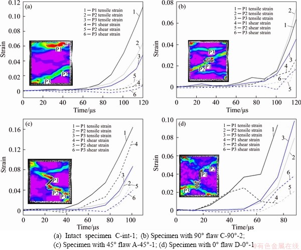
Figure 15 Tensile and shear strain evolution at key points along macro fractures:
Contributors
XIAO Peng conducted literature review, investigation, and wrote the original draft of the manuscript. LI Di-yuan and ZHANG Chun-shun provided the concept, supervision, review-writing and editing. ZHAO Guo-yan, ZHU Quan-qi and LIU Huan-xin provided methodology, software and data curation.
Conflict of interest
XIAO Peng, LI Di-yuan, ZHANG Chun-shun, ZHAO Guo-yan, ZHU Quan-qi and LIU Huan-xin declare that they have no conflict of interest.
References
[1] LI Chun-lin, PRIKRYL R, NORDLUND E. The stress-strain behaviour of rock material related to fracture under compression [J]. Engineering Geology, 1998, 49(3, 4): 293-302. DOI: 10.1016/S0013-7952(97)00061-6.
[2] MALAN D, BASSON F. Ultra-deep mining: The increased potential for squeezing conditions [J]. Journal of the South African Institute of Mining and Metallurgy, 1998, 98(11, 12): 353-363.
[3] LI Xi-bing, ZHOU Zi-long, YE Zhou-yuan, MA Chun-de, ZHAO Fu-jun, ZUO Yu-jun, HONG Liang. Study of rock mechanical characteristics under coupled static and dynamic loads [J]. Chinese Journal of Rock Mechanics and Engineering, 2008, 27: 1387-1395. (in Chinese)
[4] GONG Feng-qiang, ZHAO Gao-feng. Dynamic indirect tensile strength of sandstone under different loading rates [J]. Rock Mechanics and Rock Engineering, 2014, 47(6): 2271-2278. DOI: 10.1007/s00603-013-0503-7.
[5] LI Di-yuan, WONG L N Y. The Brazilian disc test for rock mechanics applications: Review and new insights [J]. Rock Mechanics and Rock Engineering, 2013, 46(2): 269-287. DOI: 10.1007/s00603-012-0257-7.
[6] GONG Feng-qiang, SI Xue-feng, LI Xi-bing. Dynamic triaxial compression tests on sandstone at high strain rates and low confining pressures with split Hopkinson pressure bar [J]. International Journal of Rock Mechanics and Mining Sciences, 2019, 113: 211-219. DOI: 10.1016/j.ijrmms.2018. 12.005.
[7] LI Xi-bing, FENG Fan, LI Di-yuan, DU Kun, RANJITH P G, ROSTAMI J. Failure characteristics of granite influenced by sample height-to-width ratios and intermediate principal stress under true-triaxial unloading conditions [J]. Rock Mechanics and Rock Engineering, 2018, 51(5): 1321-1345. DOI: 10.1007/s00603-018-1414-4.
[8] LI Xi-bing, GONG Feng-qiang, TAO Ming, DONG Long-jun, DU Kun, MA Chun-de, ZHOU Zi-long, YIN Tu-bing. Failure mechanism and coupled static-dynamic loading theory in deep hard rock mining: A review [J]. Journal of Rock Mechanics and Geotechnical Engineering, 2017, 9(4): 767-782. DOI: 10.1016/j.jrmge.2017.04.004.
[9] LIU Zhi-xiang, HAN Ke-wen, YANG Shan, LIU Yu-xi. Fractal evolution mechanism of rock fracture in undersea metal mining [J]. Journal of Central South University, 2020, 27(4): 1320-1333. DOI: 10.1007/s11771-020-4369-z.
[10] LI Xi-bing, ZHOU Zi-long, LOK Tat-seng, HONG Liang, YIN Tu-bing. Innovative testing technique of rock subjected to coupled static and dynamic loads [J]. International Journal of Rock Mechanics and Mining Sciences, 2008, 45(5): 739-748. DOI: 10.1016/j.ijrmms.2007.08.013.
[11] ZHOU Zi-long, LI Xi-bing, ZOU Yang, JIANG Yi-hui, LI Guo-nan. Dynamic Brazilian tests of granite under coupled static and dynamic loads [J]. Rock Mechanics and Rock Engineering, 2014, 47(2): 495-505. DOI: 10.1007/s00603-013-0441-4.
[12] TAO Ming, MA Ao, CAO Wen-zhuo, LI Xi-bing, GONG Feng-qiang. Dynamic response of pre-stressed rock with a circular cavity subject to transient loading [J]. International Journal of Rock Mechanics and Mining Sciences, 2017, 99: 1-8. DOI: 10.1016/j.ijrmms.2017.09.003.
[13] LI Di-yuan, XIAO Peng, HAN Zhen-yu, ZHU Quan-qi. Mechanical and failure properties of rocks with a cavity under coupled static and dynamic loads [J]. Engineering Fracture Mechanics, 2020, 225: 106195. DOI: 10.1016/j.engfracmech.2018.10.021.
[14] LI Di-yuan, ZHU Quan-qi, ZHOU Zi-long, LI Xi-bing, RANJITH P G. Fracture analysis of marble specimens with a hole under uniaxial compression by digital image correlation [J]. Engineering Fracture Mechanics, 2017, 183: 109-124. DOI: 10.1016/j.engfracmech.2017.05.035.
[15] LI Huan-qiang, WONG L N Y. Influence of flaw inclination angle and loading condition on crack initiation and propagation [J]. International Journal of Solids and Structures, 2012, 49(18): 2482-2499. DOI: 10.1016/j.ijsolstr.2012.05.012.
[16] LUO Yong, GONG Feng-qiang, LI Xi-bing, WANG Shan-yong. Experimental simulation investigation of influence of depth on spalling characteristics in circular hard rock tunnel [J]. Journal of Central South University, 2020, 27(3): 891-910. DOI: 10.1007/s11771-020-4339-5.
[17] YANG Sheng-qi, HUANG Yan-hua, TIAN Wen-ling, ZHU Jian-bo. An experimental investigation on strength, deformation and crack evolution behavior of sandstone containing two oval flaws under uniaxial compression [J]. Engineering Geology, 2017, 217: 35-48. DOI: 10.1016/ j.enggeo.2016.12.004.
[18] ZHANG Xiao-ping, WONG L N Y. Cracking processes in rock-like material containing a single flaw under uniaxial compression: A numerical study based on parallel bonded- particle model approach [J]. Rock Mechanics and Rock Engineering, 2012, 45(5): 711-737. DOI: 10.1007/s00603- 011-0176-z.
[19] ZHU Quan-qi, LI Di-yuan, HAN Zhen-yu, LI Xi-bing, ZHOU Zi-long. Mechanical properties and fracture evolution of sandstone specimens containing different inclusions under uniaxial compression [J]. International Journal of Rock Mechanics and Mining Sciences, 2019, 115: 33-47. DOI: 10.1016/j.ijrmms.2019.01.010.
[20] WONG R H C, LIN P, TANG C A. Experimental and numerical study on splitting failure of brittle solids containing single pore under uniaxial compression [J]. Mechanics of Materials, 2019, 115: 33-47. DOI: 10.1016/ j.mechmat.2005.05.017.
[21] LI Xi-bing, ZHOU Tao, LI Di-yuan. Dynamic strength and fracturing behavior of single-flawed prismatic marble specimens under impact loading with a split-Hopkinson pressure bar [J]. Rock Mechanics and Rock Engineering, 2017, 50(1): 29-44. DOI: 10.1007/s00603-016-1093-y.
[22] TAO Ming, ZHAO Hua-tao, LI Xi-bing, LI Xiang, DU Kun. Failure characteristics and stress distribution of pre-stressed rock specimen with circular cavity subjected to dynamic loading [J]. Tunnelling and Underground Space Technology, 2018, 81: 1-15. DOI: 10.1016/j.tust.2018.06.028.
[23] WENG Lei, LI Xi-bing, TAHERI A, WU Qiu-hong, XIE Xiao-feng. Fracture evolution around a cavity in brittle rock under uniaxial compression and coupled static-dynamic loads [J]. Rock Mechanics and Rock Engineering, 2018, 51(2): 531-545. DOI: 10.1007/s00603-017-1343-7.
[24] WENG Lei, WU Zhi-jun, LI Xi-bing. Mesodamage characteristics of rock with a pre-cut opening under combined static-dynamic loads: A nuclear magnetic resonance (NMR) investigation [J]. Rock Mechanics and Rock Engineering, 2018, 51(8): 2339-2354. DOI: 10.1007/s00603-018-1483-4.
[25] DONG Wei, WU Zhi-min, ZHOU Xiang-ming, WANG Na, KASTIUKAS G. An experimental study on crack propagation at rock-concrete interface using digital image correlation technique [J]. Engineering Fracture Mechanics, 2017, 171: 50-63. DOI: 10.1016/j.engfracmech.2016.12.003.
[26] MUNOZ H, TAHERI A, CHANDA E K. Pre-peak and post-peak rock strain characteristics during uniaxial compression by 3D digital image correlation [J]. Rock Mechanics and Rock Engineering, 2016, 49(7): 2541-2554. DOI: 10.1007/s00603-016-0935-y.
[27] SONG H, ZHANG H, FU D, KANG Y, HUANG G, QU C, CAI Z. Experimental study on damage evolution of rock under uniform and concentrated loading conditions using digital image correlation [J]. Fatigue & Fracture of Engineering Materials & Structures, 2013, 36(8): 760-768. DOI: 10.1111/ffe.12043.
[28] ZHANG Hao, FU Dong-hui, SONG Hai-peng, KANG Yi-lan, HUANG Gan-yun, QI Gang, LI Jian-yu. Damage and fracture investigation of three-point bending notched sandstone beams by DIC and AE techniques [J]. Rock Mechanics and Rock Engineering, 2015, 48(3): 1297-1303. DOI: 10.1007/s00603-014-0635-4.
[29] ZHOU Zi-long, CAI Xin, LI Xi-bing, CAO Wen-zhuo, DU Xue-ming. Dynamic response and energy evolution of sandstone under coupled static-dynamic compression: Insights from experimental study into deep rock engineering applications [J]. Rock Mechanics And Rock Engineering, 2020, 53(3): 1305-1331. DOI: 10.1007/s00603-019- 01980-9.
[30] GONG Feng-qiang, LI Xi-bing, LIU Xi-ling. Experimental study of dynamic characteristics of sandstone under one- dimensional coupled static and dynamic loads [J]. Chinese Journal of Rock Mechanics and Engineering, 2010, 29(10): 2076-2085. (in Chinese)
[31] LI Xi-bing. The foundation and application of dynamics of rock [M]. Beijing: Science Press, 2013. (in Chinese)
[32] ZHOU Y X, XIA K, LI X B, MA G W, ZHAO J, ZHOU Z L, DAI F. Suggested methods for determining the dynamic strength parameters and mode-I fracture toughness of rock materials [J]. International Journal of Rock Mechanics and Mining Sciences, 2012, 49: 105-112. DOI: 10.1016/j.ijrmms. 2011.10.004.
(Edited by ZHENG Yu-tong)
中文导读
动静组合加载下含不同倾角裂隙岩石的力学特性与破坏规律
摘要:深部裂隙岩体开挖受初始地应力和外界动力扰动的共同作用。本文基于改进的霍普金森压杆和数字图像相关技术,对完整和含不同裂隙倾角的花岗岩进行预静载下的冲击试验,研究了动静组合加载下预制裂隙对岩石动态力学响应和破坏特性的影响规律。结果表明,完整试样和含不同裂隙倾角试样的峰值应变和动态强度随着轴向静压的增加而减小,加载方向90°的裂隙对峰值应变、动态强度和组合强度只有较弱的降低程度,而45°和0°裂隙则有明显的降低作用。含90°裂隙试样在中低轴向静压下发生剪切-拉伸复合破坏,在高轴向静压下发生剪切破坏。含45°和0°裂隙试样在不同的轴向静压下由于预制裂隙的影响均发生宏观剪切破坏。基于数字图像相关技术发现,在宏观裂纹(包括剪切和拉伸裂纹)形成前的微裂纹均属于拉伸裂纹,含45°和0°裂隙试样,在预制裂隙尖端要远早于其他位置产生的拉应变和剪应变集中。
关键词:SHPB系统;数字图像相关;动静组合加载;裂隙;裂纹扩展
Foundation item: Project(2019JJ20028) supported by the Outstanding Youth Science Foundations of Hunan Province of China; Project(51774321) supported by the National Natural Science Foundation of China; Project(2018YFC0604606) supported by the State Key Research Development Program of China
Received date: 2020-06-09; Accepted date: 2020-08-30
Corresponding author: LI Di-yuan, PhD, Professor; Tel: +86-13517407018; E-mail: diyuan.li@csu.edu.cn; ORCID: https://orcid.org/ 0000-0002-4181-5463

