激光冲击强化改善Ti-6Al-4V合金冲击磨损性能
来源期刊:中国有色金属学报(英文版)2019年第7期
论文作者:尹美贵 蔡振兵 李正阳 周仲荣 王文建 何卫锋
文章页码:1439 - 1448
关键词:Ti-6Al-4V合金;激光冲击强化;冲击磨损;冲击动能;磨损机理
Key words:Ti-6Al-4V alloy; laser shock peening; impact wear; impact kinetic energy; wear mechanism
摘 要:采用自制的冲击磨损实验台研究激光冲击强化工艺(LSP)对Ti-6Al-4V合金冲击磨损性能的影响,并对材料强化后的显微组织及力学性能进行分析。通过冲击磨损实验研究样品在不同冲击动能作用下的动能吸收、冲击力、磨损接触时间和磨损机理。实验结果表明,经激光冲击强化后,Ti-6Al-4V合金表面的显微硬度、弹性模量和内部残余压应力等均得到显著提高,其磨损抗性也得到显著改善,且强化能量越高,其改善效果越明显。此外,样品的磨损机理为磨粒磨损、氧化磨损和疲劳剥落。
Abstract: The effects of laser shock peening (LSP) on the impact wear behavior of Ti-6Al-4V alloys were investigated by a homemade impact wear test rig. The microstructure and mechanical properties of the peened samples were studied. During the impact wear test, the energy absorption, impact force, wear contact time and wear mechanism of all the test samples were investigated in terms of the influence of the impact kinetic energy. The results showed that microhardness, elastic modulus and residual compressive stress of the treated samples were markedly improved. The wear resistances of both treated samples were highly improved after LSP, and a higher pulse energy corresponded to a more obvious effect. Besides, the wear in all test samples involved a combination of abrasive and oxidation wear and fatigue spalling.
Trans. Nonferrous Met. Soc. China 29(2019) 1439-1448
Mei-gui YIN1, Zhen-bing CAI1, Zhen-yang LI1, Zhong-rong ZHOU1, Wen-jian WANG1, Wei-feng HE2
1. Tribology Research Institute, Key Laboratory of Advanced Technologies of Materials of Ministry of Education, Southwest Jiaotong University, Chengdu 610031, China;
2. Key Laboratory of Science and Technology on Plasma Dynamics, Air Force Engineering University, Xi’an 710038, China
Received 9 July 2018; accepted 4 March 2019
Abstract: The effects of laser shock peening (LSP) on the impact wear behavior of Ti-6Al-4V alloys were investigated by a homemade impact wear test rig. The microstructure and mechanical properties of the peened samples were studied. During the impact wear test, the energy absorption, impact force, wear contact time and wear mechanism of all the test samples were investigated in terms of the influence of the impact kinetic energy. The results showed that microhardness, elastic modulus and residual compressive stress of the treated samples were markedly improved. The wear resistances of both treated samples were highly improved after LSP, and a higher pulse energy corresponded to a more obvious effect. Besides, the wear in all test samples involved a combination of abrasive and oxidation wear and fatigue spalling.
Key words: Ti-6Al-4V alloy; laser shock peening; impact wear; impact kinetic energy; wear mechanism
1 Introduction
The Ti-6Al-4V (TC4) titanium alloy is widely used in the aerospace, energy, weapons and other industries, because of its excellent properties such as low density, high specific strength and excellent corrosion resistance [1-3]. However, its wider application is hindered by its poor tribological properties and low surface hardness [4,5]. In recent years, researchers have proposed many different surface-strengthening tech- nologies such as surface coating technology [6], shot peening method [7], and high current pulsed electron beam [8] to improve the wear resistance and fatigue performance of this alloy. Laser shock peening (LSP) technology mainly changes the microstructure of metal near the surface by high-density laser shock wave. The microstructural changes finally lead to the improvement of some mechanical properties, such as hardness and fatigue strength [9,10]. REN et al [11] found that dislocation movement was the primary reason behind the grain refinement of Ti-6Al-4V alloy under laser shock processing. KUMAR et al [12] affirmed that the fretting wear volume of Ti-6Al-4V significantly decreased after being treated by LSP. ZHOU et al [13] investigated that the residual stress introduced by LSP had a positive effect on prolonging the fatigue life of Ti-6Al-4V. However, few studies have explored the effect of LSP on the impact wear resistance of Ti-6Al-4V.
In the aero industry, the blades of aircraft engines are always subjected to heavy wear caused by dust, sand, and other particles that are entrained by airflow [14,15]. Various studies have been conducted to investigate the wear mechanism and response of this kind wear conditions. SAHOO et al [16] found that compared with impact angle or size of particles, impact velocity was the most significant factor influencing the wear performance of Ti-6Al-4V alloy. GUJBA et al [17] studied the water droplet erosion behavior of Ti-6Al-4V, and they observed that the impact speed influenced the erosion initiation time and the maximum erosion rates. ZHOU et al [18] showed that the angle displacement amplitude and the tilt angle intensively affected the dual-rotational fretting behavior of titanium alloy. However, by now, most of the current studies are highly dependent on the wear morphology or mechanisms of the tested materials. During the wear process, the changes in the dynamic wear response were lacking. The test rig used in this study can provide various initial impact velocities and realize different impact wear cycles by changing the motion status of the motor [19]. The changes of impact force and impact kinetic energy versus time can be collected during the whole wear process [20,21].
This study aims to compare the impact wear behavior of two different treated and one untreated TC4 titanium alloys. The quantitative and qualitative differences in impact kinetic energy, impact force, and wear damage were assessed to determine the effectiveness of LSP technology.
2 Experimental
2.1 Materials
The TC4 sample employed in this study is widely used in aeronautics. The chemical composition (in mass fraction) of this alloy consisted of 6% Al, 4.3% V, 0.16% Fe, 0.01% C, 0.01% N, 0.18% O, 0.004% H, and balanced Ti. Prior to LSP, all of the samples were polished with SiC papers and a polishing cloth. After the processing, all samples were washed with alcohol in an ultrasonic bath, and then dried under compressed air.
2.2 Laser shock peening
Figure 1 shows a schematic diagram of LSP. Prior to LSP, a special coating was glued onto the sample’s surface. This coating layer increased the absorbance of laser energy and prevented the sample’s surface from overheating when irradiated with high-power laser beam, and plasmas were formed on the irradiated surface. Water was added to prevent the plasma from expanding away from the surface to obtain a high-magnitude shock wave, which was then transmitted to the sample. In this experiment, a laser with a wavelength of 1064 nm, a spot diameter of 3 mm, and a pulse duration of 10 ns was applied. Both treated samples were peened twice with laser pulse energy of 5 and 7 J, respectively.
2.3 Impact wear test method
This study was performed on a homemade impact wear test rig (Fig. 2). During the impact wear test, the velocity of the voice coil motor, which was the power source of the impact block’s impact kinetic energy, always changed along a certain sine rule. During each impact cycle, the voice coil motor first hit the impact block via a dumping punch. When the speed of impact block reached the maximum transient velocity value (vi) of the voice coil motor, which was set prior to the test, the impact block separated from the magnetic chuck and impacted the specimen through the impact head with an approximately constant velocity, because the impact block was fixed on the liner motion guide, which had a low friction coefficient. Finally, after impacting the test sample, the impact block rebounded and performed a return motion with a rebound velocity (vr).
This rig had two sensors, one was a piezoelectric force sensor, which was fixed between the sample fixture and the support structure. This sensor can record the impact force produced once the impact head hits the specimens. The other was a velocity sensor which can measure the impact and rebound velocities of the impact block during each impact cycle. All data can be well collected by the data acquisition unit and sent to a software in the computer.
To elucidate the effects of LSP on the impact wear resistance of TC4 titanium alloys, three test samples were untreated, 5 J treated and 7 J treated, respectively. Four different initial impact velocities (60, 90, 120 and 150 mm/s) were applied to the impact test, the mass of impact block was 425 g, and the number of impact cycles for each test was 1×10⁵. Each test was repeated three times to ensure the accuracy of the test results. To examine the wear condition of each specimen, a silicon nitride ceramic ball (d=7.15 mm) was used as an impact head because of its relatively high elastic modulus.
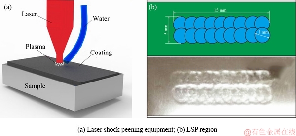
Fig. 1 Schematic diagrams of LSP
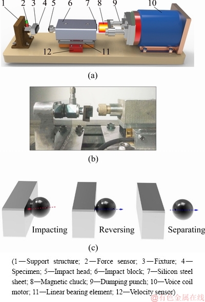
Fig. 2 Schematics of impact rig (a) and morphology of impact wear test equipment (b) and impact wear processing (c)
After the impact wear tests were conducted, the surface morphologies of all wear scars were observed through scanning electron microscopy (SEM, JSM- 6610). A 3D optical microscope (Bruker Contour GT-1) was used to obtain the profiles of all wear scars, and an electron probe micro-analyzer was utilized to identify the chemical composition of the wear surface. Data from both sensors were analyzed to investigate the responses of the impact force and the kinetic energy during the testing process.
3 Results
3.1 Material characteristics
Both peened samples were analyzed by EBSD to study the near-surface misorientations, microstructures and plastic deformation. Samples of 4 mm × 3 mm × 1 mm were prepared, and then subjected to mechanical polishing and electrolytic polishing. EBSD test was conducted on a Hitachi S-3400N SEM equipped with an HKL-EBSD system. The measurements were made at an operating voltage of 20 kV in an area of 250 μm ×200 μm using a step size of 0.15 μm.
Figures 3(a) and (b) show the measured kernel average misorientation (KAM) maps of the samples treated with 5 and 7 J, respectively. KAM was used to represent the average misorientation between a given point and its nearest neighbors which belongs to the same grain. KAM is often used to assess the local plastic strain in specimens. The higher kernel value always means the increase of the dislocation density and in-grain structure evolution [22,23]. A higher level of KAM is shown in the brighter green color in the grains, and the sample treated with 7 J had a higher level of KAM than that treated with 5 J. The Nano Map-Dual Mode 3D profilometer was used to observe the surface topography of both treated samples. The altitude variation of the untreated sample was approximately 0.2 μm, whereas the maximum altitudes of the samples treated with 5 and 7 J were 2.5 and 3.4 μm, respectively (Figs. 3(c) and (d)). During LSP, the pressure of the shock wave was greater than the dynamic field strength of the target material. Plastic deformation was generated due to residual compressive stresses and structural changes on the surface. A higher pulse energy always displayed a more obvious effect.
The X-ray diffraction (XRD) tests were applied to identifying phases in the samples. The diffraction data were collected over a 2θ range of 30°-90°, with a step width of 0.02° and a counting time of 5 s per step.
Figure 4(a) shows the XRD patterns of three different test samples. The main phases are still α, and there is no additional peak after different LSP impacts, which means that there is no new phase. The peaks are broadened and become smooth after LSP, and the peak broadening is usually attributed to dislocation density increasing and grain refinement. The average sizes of the α grain of the samples treated with 5 and 7 J were 9.98 and 8.93 μm, respectively, and their corresponding grain aspect ratios are about 1.96 and 2.18. These results indicated that the shape of the α grains tended to become slender as the pulse energy increased (Fig. 4(b)).
A standard Vickers indenter with an indentation load of 500 g and the dwell time of 10 s was used, and the surface was slightly polished before measurement. The proto-LXRD X-ray diffractometer was used to measure the residual stress on the cross section, and all residual stress measurements were performed by the sin2ψ (where ψ is the tilt angle, ψ=45°) technique. The sample was removed layer by layer via electrolytic polishing with certain corrosion solution at a corrosion rate of 0.3 μm/(cm2·s)
Figure 5(a) shows the microhardness distribution on the cross-section of the three TC4 titanium alloy specimens. The original hardness of the untreated sample was HV0.5 390. LSP can moderately increase the microhardness. The surface hardness values of the 5 and 7 J treated samples were HV0.5 440 and HV0.5 470, respectively. The increased hardness can be attributed to two factors. One is that a severe plastic layer was generated, and the material surface underwent work hardening, the other is that grain refinement can also improve the specimen’s hardness according to the Hall-Petch formula.
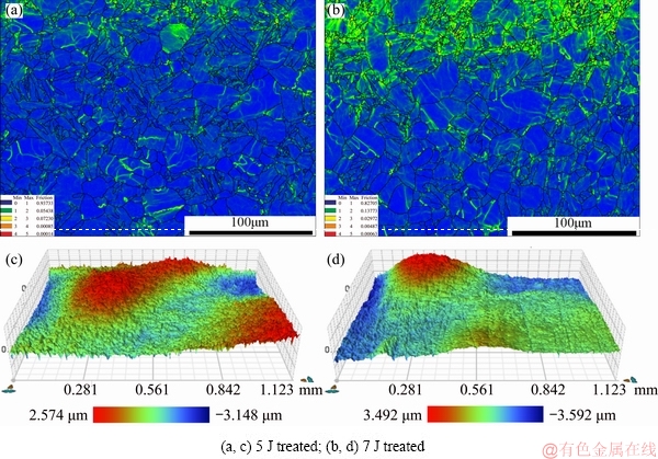
Fig. 3 KAM maps (a, b) and 3D surface topographies (c, d) of both treated samples
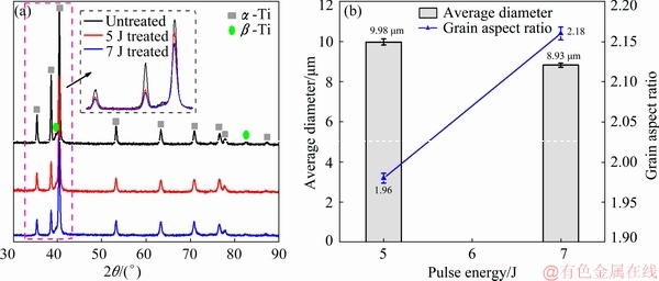
Fig. 4 XRD patterns of three test samples (a) and grain size of both treated samples (b)
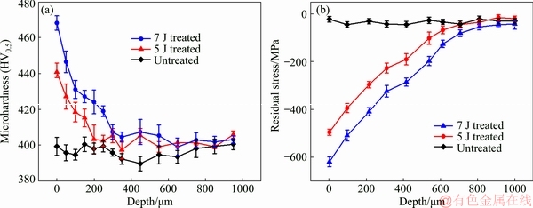
Fig. 5 Microhardness (a) and residual stress (b) distributions of three test samples
Figure 5(b) shows the depth distribution of the residual stress of the three specimens. It can be seen that LSP caused the specimens to generate high compress residual stress within a certain depth. The highest compress residual stress occurred on a treated surface. The maximum residual stresses of the material surface reached 495 and 625 MPa for the samples treated with 5 and 7 J, respectively. The compressive stresses were formed under the combinatorial effects of plastic deformation and volume limitation. These compressive stresses declined as the shock wave propagated into the interior of the peened sample.
3.2 Dynamic behavior
Figure 6 shows the load-displacement curves of the three test samples that were obtained by nano-indentation test. The maximum load for the test was 5 mN, the upload and download rates were 0.5 mN/s, and the duration time for maximum load was 5 s. The indentation depths of untreated, 5 J and 7 J treated samples were approximately 256, 209 and 172 nm, respectively, and the corresponding plastic depths were approximately 188, 135 and 123 nm. These values indicated that the treated titanium alloy possessed a good combination plasticity and hardness properties.
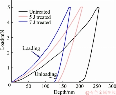
Fig. 6 Load-displacement curves for three specimens
During the horizontal dynamic impact process, the maximum impact stress was always determined by the dynamic load coefficient Kd (Formula (1)). The maximum strain energy was directly proportional to the dynamic displacement Δdmax (Formula (2)) during each impact cycle, where vi denotes the initial impact velocity, and Δst represents the static load displacement. As shown in Fig. 6, the highest to lowest static load displacement was observed sequentially in the untreated, 5 J treated, and 7 J treated samples. Hence, the 7 J treated sample always exhibited the highest impact stress and lowest strain energy.
 (1)
(1)
 (2)
(2)
In this study, a method based on dynamic response under impact loading was applied to evaluating the wear performance of the specimens treated with different laser pulse energies. Theoretically, the changes of the material’s mechanical properties would affect the response of the impact wear to some extent.
The initial impact kinetic energy (Ei) of the impact block was determined by its initial velocity (v) and mass (m), and was calculated by the simple formula mv2/2. In this study, the mass of the impact block was 425 g. As such, a higher initial impact velocity corresponded to a greater impact kinetic energy. Figure 7 shows the changes of the impact kinetic energy under various impact velocities and their distinct tendencies of these three test samples. For each test specimen, the rebound kinetic energy and the absorbed energy increased with increasing impact kinetic energy. When the initial impact velocity was 60 mm/s, the energy absorption rates of the untreated, 7 J and 5 J treated specimens were 45.06%, 40.2% and 32.05%, respectively. The corresponding energy absorption rates decreased to 30.0%, 25.13% and 22.13% with increasing impact velocity up to 150 mm/s. Each sample’s energy absorption rate did not significantly change with increasing impact cycles.

Fig. 7 Kinetic energy versus content time at initial impact velocities of 60 mm/s (a) and 150 mm/s (b) and energy absorption rate versus impact velocity at impact cycles of N=1×10⁵ (c) for three test samples
Figure 8 shows the impact forces and their peak values of the three test samples under different initial impact velocities. For each specimen, the peak impact force (F) increased with increasing initial impact velocity (vi), and the real contact time (t) decreased with increasing initial impact velocity (vi). In comparison, under the same initial impact velocity, the test sample treated with pulse energy of 7 J always exhibited the largest impact force and the shortest real contact time. When the initial impact velocity was 60 mm/s, the peak impact force and the real contact time were 118.31 N and 0.66 ms for the 7 J treated sample and 88.56 N and 0.80 ms for the untreated specimen (Fig. 8(a)). As the initial impact velocity increased to 150 mm/s, the maximum impact force and the real contact time were 316.89 N and 0.60 ms for the 7 J treated sample and 281.13 N and 0.70 ms for the untreated specimen (Fig. 8(b)). Thus, the sample treated with a higher pulse energy always produced a higher contact peak force and a shorter contact time (Fig. 8(c)). These results can be attributed to the increased surface microhardness of the material and the unevenness caused by LSP. The maximum contact force of the three specimens lightly fluctuated as the impact cycles increased, whereas the contact time of the three specimens showed a slightly upward trend (Fig. 8(d)), which may be due to the production of wear debris during the impact wear process.
3.3 Wear analysis
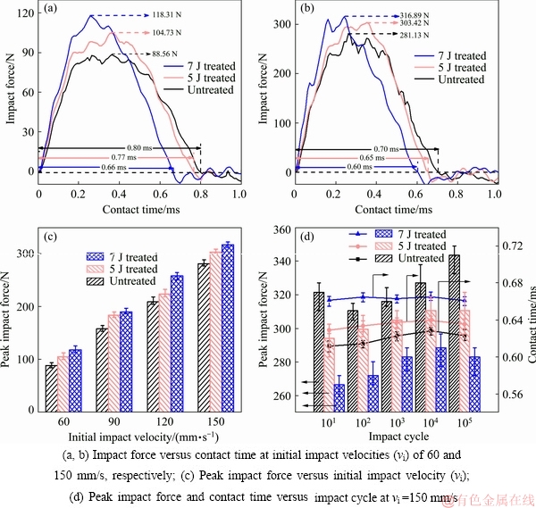
Fig. 8 Waveforms and peak values of impact force
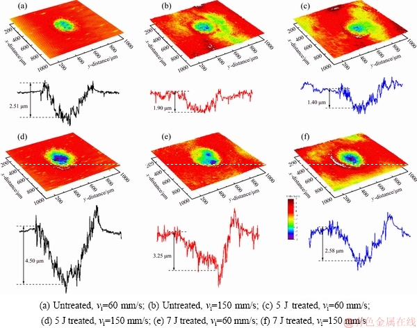
Fig. 9 3D-profile micrographs of worn scars of three test samples
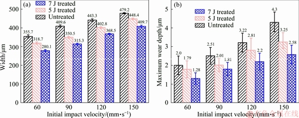
Fig. 10 Width (a) and maximum wear depth (b) of wear scars of three test samples at various impact velocities and N=1×10⁵
Figure 9 shows the 3D-profile micrographs of the worn scars of the three test samples, which were subjected to impact velocities of 60 and 150 mm/s. The width and maximum depth of all worn scars of three test samples under different initial impact velocities are presented in Figs. 10(a) and (b), respectively. Figure 10(a) shows that when the initial impact velocity was 60 mm/s, the widths of wear scars of the untreated, 5 J and 7 J samples are 355.7, 318.7, and 280.1 μm. When the initial impact velocity was increased to 150 mm/s, the widths of the corresponding samples were 479.2, 448.4, and 409.7 μm, respectively. Under the same impact velocity, the wear scar of the 7 J treated sample always had the shortest width; whereas that of the untreated sample was always the longest. The main reason is that the microhardness of the TC4 titanium alloy can be increased through LSP, and higher pulse energy would produce more obvious effect.
For each test sample, the depth of the wear scars increased with increasing the initial impact velocity. The reason is that a high speed always produced a high impact kinetic energy in the impact block, and greater energy input would cause a severer material damage during the impact wear. The maximum wear depths of the 7 J, 5 J and untreated test samples were 1.28, 1.79 and 2.0 μm respectively when the initial impact velocity was 60 mm/s, and 2.58, 3.25 and 4.3 μm respectively when the impact velocity was increases to 150 mm/s. The 7 J treated test specimen always exhibited better wear resistance than the other two specimens under the same initial impact velocity (Fig. 10(b)).
Figure 11 shows the micro-morphologies at the center of the worn scars of the three test samples. During the impact wear processes of each cycle, the shear stresses, which would result in the ignition and propagation of micro-cracks, always occurred on the subsurface of the scars. High-power SEM revealed that the topography of the wear scar of the untreated specimen was characterized by delamination cracks and debris, indicating that a fatigue delamination wear occurred under the impact force. The 5 J treated test sample also exhibited slight delamination cracks and debris, but their extent was significantly less than that of the untreated specimen. The failure mode of the 7 J treated test sample was primarily fatigue spalling, and delamination cracks can hardly be observed. The surface hardness, which can improve the wear resistance, and the compressive residual stress, which can hinder cracks extension, would be increased after treatment. Higher pulse energy always corresponded to less damage of the sample under the same impact energy.
Figure 12 shows cross-section morphologies of the worn scars of three test samples. Delamination cracks caused by impact fatigue effect can be clearly observed on the untreated sample, and these cracks eventually led to detachment and removal of materials. A few small cracks occurred on the test sample treated by pulse energy of 5 J, while for the 7 J treated test sample almost no delamination damage existed. These findings indicated that compressive residual stress was introduced after LSP, and this kind stress can extend the fatigue life of the metal components. In addition, residual stress can not only impede the initiation of fatigue cracks, but also reduce the extension speed of delamination. Thus, higher pulse energy causes more distinct effect.
Figure 13 shows the EPMA distribution mapping images of O and Ti elements on the worn scars after the test. The shape of all worn scars was nearly circular. The highest to lowest average contents of O and Ti elements can be observed sequentially in the untreated, 5 J treated and 7 J treated specimens. The appearance of O was due to the accumulated wear debris, and the damage of the TC4 alloy was oxidative wear. Titanium element mainly originated from the wear debris. More wear debris corresponded to higher contents of titanium elements. Given that the untreated specimen had a poorer wear resistance than both treated samples, the untreated sample always exhibited the most serious wear under the same impact wear condition. When treated with higher pulse energy, the wear resistance increased. As such, the wear scar of the 7 J treated sample always exhibited the lowest contents of O and Ti elements.
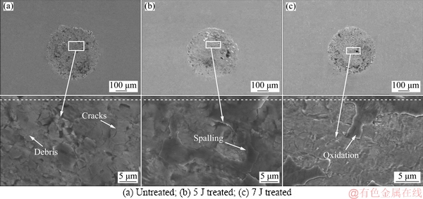
Fig. 11 Micro-morphologies at center of worn scars of three test samples at initial impact velocity of 150 mm/s and N=1×10⁵
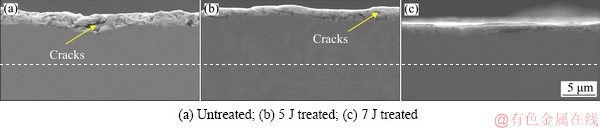
Fig. 12 Cross-section morphologies of worn scars of three test samples
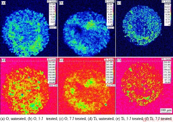
Fig. 13 EPMA element mapping images of wear scars of three test samples at vi=150 mm/s and N=1×10⁵
4 Conclusions
(1) LSP induced work hardening and low angle misorientation near the surface of TC4 titanium alloy. The improvement in the impact wear resistance of TC4 titanium alloy after LSP was attributed to the increased surface hardness and compressive residual stress.
(2) Under the same impact wear condition, the test sample treated by pulse energy of 7 J always experienced the most significant impact force; however, the impact contact time and the kinetic energy absorption rate were the smallest. The results of the untreated one are just the opposite.
(3) The wear morphologies of wear scars of test samples demonstrated that the impact wear resistance of the TC4 alloy was significantly improved after LSP. The primary wear mechanism was fatigue delamination, and friction oxidation also occurred in the wear zones.
References
[1] YUMAK N, ASLANTAS K, PEKBEY Y. Effect of cryogenic and aging treatments on low-energy impact behaviour of Ti-6Al-4V alloy [J]. Transactions of Nonferrous Metals Society of China, 2017, 27(3): 514-526.
[2] ZHOU Wang-fan, REN Xu-dong, LIU Fan-fan, REN Yun-peng. Nanocrystallization in the duplex Ti-6Al-4V alloy processed by multiple laser shock peening [J]. Metals, 2016, 6(12): 297-306.
[3] HONG S U N, YU L M, LIU Y C, ZHANG L Y, LIU C X, LI H J, WU J F. Effect of heat treatment processing on microstructure and tensile properties of Ti-6Al-4V-10Nb alloy [J].Transactions of Nonferrous Metals Society of China, 2019,29(1): 59-66.
[4] HUANG S, ZHU Y, GUO W, PENG P, DIAO X. Impact toughness and microstructural response of Ti-17 titanium alloy subjected to laser shock peening [J]. Surface and Coatings Technology, 2017, 327: 32-41.
[5] WENG Fei, CHEN Chuan-zhong, YU Hui-jun. Research status of laser cladding on titanium and its alloys: A review [J]. Materials & Design, 2014, 58: 412-425.
[6] QIAO Juan, ZHU Li-na, YUE Wen, FU Zhi-qiang, KANG Jia-jie, WANG Cheng-biao. The effect of attributes of micro-shapes of laser surface texture on the wettability of WC-CrCo metal ceramic coatings [J]. Surface and Coatings Technology, 2018, 334: 429-437.
[7] STRINGER J, MARSHALL M B. High speed wear testing of an abradable coating [J]. Wear, 2012, 294: 257-263.
[8] YU Shou-ming, LIU Dao-xin, ZHANG Xiao-hua, DU Dong-xing. Effects of combined plasma chromizing and shot peening on the fatigue properties of a Ti6Al4V alloy [J]. Applied Surface Science, 2015, 353: 995-1002.
[9] KUMAR S A, SUNDAR R, RAMAN S G S, KUMAR H, KAUL R, RANGANATHAN K, OAK S M, KUKREJA L M, BINDRA K S. Influence of laser peening on microstructure and fatigue lives of Ti-6Al-4V [J]. Transactions of Nonferrous Metals Society of China, 2014, 24(10): 3111-3117.
[10] NIE Xiang-fan, HE Wei-feng, ZANG Shun-lai, WANG Xue-de, ZHAO Jie. Effect study and application to improve high cycle fatigue resistance of TC11 titanium alloy by laser shock peening with multiple impacts [J]. Surface and Coatings Technology, 2014, 253: 68-75.
[11] REN X D, ZHOU W F, LIU F F, REN Y P, YUAN S Q, REN N F, XU S D, YANG T. Microstructure evolution and grain refinement of Ti-6Al-4V alloy by laser shock processing [J]. Applied Surface Science, 2016, 363: 44-49.
[12] KUMAR D, AKHTAR S N, PATEL A K, RAMKUMAR J, BALANI K. Tribological performance of laser peened Ti-6Al-4V [J]. Wear, 2015, 322: 203-217.
[13] ZHOU J Z, HUANG S, ZUO L D, MENG X K, SHENG J, TIAN Q, HAN Y H, ZHU W L. Effects of laser peening on residual stresses and fatigue crack growth properties of Ti-6Al-4V titanium alloy [J]. Optics and Lasers in Engineering, 2014, 52: 189-194.
[14] BOUSSER E, MARTINU L, KLEMBER-SAPIEHA J E. Solid particle erosion mechanisms of protective coatings for aerospace applications [J]. Surface and Coatings Technology, 2014, 257: 165-181.
[15] ANANDAVEL K, PRAKASH R V. Effect of three-dimensional loading on macroscopic fretting aspects of an aero-engine blade–disc dovetail interface [J]. Tribology International, 2011, 44(11): 1544-1555.
[16] SAHOO R, MANTRY S, SAHOO T K, JHA B B. Effect of microstructural variation on erosion wear behavior of Ti-6Al-4V alloy [J]. Tribology Transactions, 2013, 56(4): 555-560.
[17] GUJBA A K, HACKEL L, KEVORKOV D, MEDRAJ M. Water droplet erosion behaviour of Ti-6Al-4V and mechanisms of material damage at the early and advanced stages [J]. Wear, 2016, 358: 109-122.
[18] ZHOU Yan, SHEN Ming-xue, CAI Zhen-bing, PENG Jin-fang, ZHU Min-hao. Study on dual rotary fretting wear behavior of Ti6Al4V titanium alloy [J]. Wear, 2017, 376: 670-679.
[19] LIN Ying-wu, CAI Zhen-bing, CHEN Zhi-qiang, QIAN Hao, TANG Li-chen, XIE Yong-Cheng, ZHU Min-hao. Influence of diameter–thickness ratio on alloy Zr-4 tube under low-energy impact fretting wear [J]. Materials Today Communications, 2016, 8: 79-90.
[20] CAI Zhen-bing, GUAN Hai-da, CHEN Zhi-qiang, QIAN Hao, TANG Li-cheng, ZHOU Zhong-rong, ZHU Min-hao. Impact fretting wear behavior of 304 stainless steel thin-walled tubes under low-velocity [J]. Tribology International, 2017, 105: 219-228.
[21] WANG Zhang, CAI Zhen-bing, SUN Yang, PENG Jin-fang, ZHU Min-hao. Low velocity impact wear behavior of MoS2/Pb nanocomposite coating under controlled kinetic energy [J]. Surface and Coatings Technology, 2017, 326: 53-62.
[22] MOHTADI-BONAB M A, ESKANDARI M, SZPUNAR J A. Texture, local misorientation, grain boundary and recrystallization fraction in pipeline steels related to hydrogen induced cracking [J]. Materials Science and Engineering A, 2015, 620: 97-106.
[23] LAINE S J, KNOWLES K M, DOORBAR P J, CUTTS R D, RUGG D. Microstructural characterisation of metallic shot peened and laser shock peened Ti-6Al-4V [J]. Acta Materialia, 2017, 123: 350-361.
尹美贵1,蔡振兵1,李正阳1,周仲荣1,王文建1,何卫锋2
1. 西南交通大学 材料先进技术教育部重点实验室 摩擦学研究所,成都 610031;
2. 空军工程大学 等离子体动力学重点实验室,西安 710038
摘 要:采用自制的冲击磨损实验台研究激光冲击强化工艺(LSP)对Ti-6Al-4V合金冲击磨损性能的影响,并对材料强化后的显微组织及力学性能进行分析。通过冲击磨损实验研究样品在不同冲击动能作用下的动能吸收、冲击力、磨损接触时间和磨损机理。实验结果表明,经激光冲击强化后,Ti-6Al-4V合金表面的显微硬度、弹性模量和内部残余压应力等均得到显著提高,其磨损抗性也得到显著改善,且强化能量越高,其改善效果越明显。此外,样品的磨损机理为磨粒磨损、氧化磨损和疲劳剥落。
关键词:Ti-6Al-4V合金;激光冲击强化;冲击磨损;冲击动能;磨损机理
(Edited by Wei-ping CHEN)
Foundation item: Project (2016YFB1102601) supported by the National Key R&D Program of China; Projects (51375407, U1530136) supported by the National Natural Science Foundation of China; Project (2017TD0017) supported by the Young Scientific Innovation Team of Science and Technology of Sichuan Province, China
Corresponding author: Zhen-bing CAI; Tel: +86-15828457775; E-mail: caizb@swjtu.cn
DOI: 10.1016/S1003-6326(19)65051-X

