Trans. Nonferrous Met. Soc. China 23(2013) 315-322
Welding characteristics of AZ31B magnesium alloy using DC-PMIG welding
Zhao-dong ZHANG, Li-ming LIU, Gang SONG
Key Laboratory of Liaoning Advanced Welding and Joining Technology, School of Materials Science and Engineering, Dalian University of Technology, Dalian 116024, China
Received 13 June 2011; accepted 9 November 2012
Abstract: Direct current pulsed metal inert-gas (DC-PMIG) welding was carried out on AZ31B magnesium alloy to obtain continuous welding joints of 3 mm and 8 mm thickness with 1.6 mm diameter of filler wire. The behavior and mechanism of metal transfer, the parameter ranges of stable welding process, the microstructure and mechanical properties of magnesium alloy were investigated. The results show that the metal transfer form of magnesium alloy using DC-PMIG welding is realized in modes of globular transfer, projected transfer and spray transfer. Welding spatter with a large size will be produced in the mode of globular transfer, and high-quality joints with few spatters can be obtained in the mode of projected transfer and spray transfer when the linear energy of filler wire is 242-271 J/cm, droplet diameter is 1.6-0.9 mm and transition frequency is 30-69 Hz. The average ultimate tensile strength of weld beads is 94.2% of that of base metals.
Key words: AZ31B magnesium alloy; DC-PMIG welding; metal transfer; welding spatter
1 Introduction
The density of magnesium alloy is as much as 2/3 of that of aluminum alloy and 1/4 of that of steel, and its specific strength and specific stiffness are both high. In addition, magnesium alloy has a wide application foreground in aviation, automobile and electronics fields with its workability, retrievability and good shockproof performance, etc [1]. With the wide application of magnesium alloy structural parts, the connection problems have to be solved. Welding is undoubtedly one of the most important methods of forming structural parts.
Although welding of magnesium alloy can be realized using diffusion bonding, friction stir welding (FSW), electron beam welding (EBW), laser beam welding (LBW), activating flux tungsten inert gas (A-TIG) welding, laser-arc hybrid welding (LAHW) [2-7], filling wire is unavoidable in the welding of thick plates. Compared to other welding methods, metal inert gas (MIG) welding is a kind of high-efficiency wire filling welding method which can achieve high-speed welding of thick plates. Moreover, MIG welding not only is capable of better gap bridging, but also can make up for the lost alloy elements during welding. However, a stable and continuous welding process is difficult to realize due to the peculiar physical properties of magnesium: the density of 1700 kg/m3, the melting point of 650 ��C and the boiling point of 1090 ��C. Molten droplet is difficult to break away from wires in a short time because both the density and surface tension coefficient of magnesium alloy are low, which makes a large droplet size for transition. Spatters with large sizes will be produced if droplets fall outside the weld pool. In addition, overheated droplets easily explode because of the little difference between the melting point and boiling point of magnesium (<500 ��C), which will make larger spatters if droplets do not transfer into the weld pool within a certain time. This makes welding heat input to filler wire precisely controlled: filler wire must be fully melted and droplets don��t explode. Some researches were carried out on magnesium alloy using MIG welding. RETHMEIER et al [8] examined MIG welding of AZ31B magnesium alloy, adopting triggered short-circuiting arc mode. UEYAMA and NAKATA [9] researched the welding of magnesium alloy using direct current pulsed MIG (DC-PMIG) welding with 1.2 mm diameter filler wire. GAO et al [10] got continuous welding joints of magnesium alloy using a 5 kW CO2 laser added with a DC-PMIG welder.
The existing reports mainly focused on the research of MIG welding process of magnesium alloy. It was found that narrow parameter range and unstable welding process with larger spatters are the main reasons for the difficult welding of magnesium alloy. In our previous work, high-quality weld beads of magnesium alloy were obtained using DC-PMIG with a pulse rework current [11] and alternating current pulsed MIG (AC-PMIG) welding [12]. The behavior of the welding spatter of magnesium alloy was investigated using DC-PMIG welding [13]. For MIG welding, welding spatter has a great influence on the stability and continuity of welding process. Hence, controlling the droplet size and metal transfer frequency within a suitable range is the key to forming weld beads with few spatters. The mode of metal transfer with a small droplet size and a high metal transfer frequency can be achieved.
This work is based on the behavior and mechanism of metal transfer. The mode of metal transfer, the effects of welding parameters on the droplet size and metal transfer frequency, the parameter ranges of stable welding process, the microstructure and the mechanical property of magnesium alloy are studied.
2 Experimental
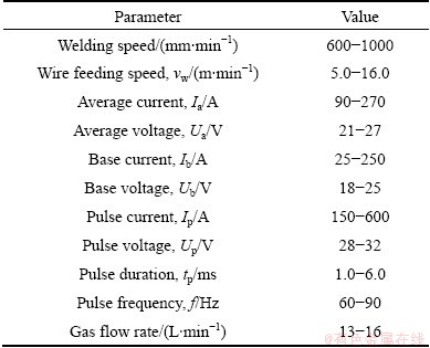
The experiments were performed on magnesium alloy plates with a DC-PMIG machine. It has the function of pulsed welding performance, adjustable pulse current and base current. The automatic device was used to weld the magnesium alloy plates with the welding speed of 200-2000 mm/min. The experimental materials were AZ31B magnesium alloy plates with the dimensions of 300 mm��180 mm��3 mm and 300 mm��130 mm��8 mm, whose surfaces were wiped and scrapped with acetone and sand paper to remove the grease and oxidation film before welding. Butt welds with the root opening of 0.8 mm in width were adopted for the plates of 3 mm thickness. While butt welds with the groove of 90�� and root face of 1 mm thickness were adopted for the plates of 8 mm thickness. The extruded magnesium wires with the diameter of 1.6 mm were used as filler wire. The compositions of base metal and filler wire are shown in Table 1, determined by X-ray fluorescence spectrometer. Parameters for DC-PMIG welding are shown in Table 2.
Argon shielding gas with a purity of 99.99% was provided coaxially with the filler wire. The state of metal transfer was monitored through a high-speed camera (CPL250KCMOS) from different directions which were perpendicular and parallel to the welding direction. The sampling frequency was 1072 frames per second. After welding, the cross-sections of the weld beads were etched in a solution comprised of 10 mL hydrochloric acid and 100 mL ethanol for 40-60 s. The microstructures of the weld beads and base metals were observed by optical microscopy (OM). Tensile specimens were examined by a tensile machine (CSS-2250) according to National Standard GB 2651��81 at a tensile rate of 2 mm/min.
Table 1 Compositions of base metal and filler wire (mass fraction, %)
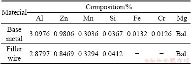
Table 2 Parameters for DC-PMIG welding
3 Results and analysis
3.1 Effects of welding parameters on mechanism of metal transfer
The results show that the metal transfer forms of magnesium alloy using DC-PMIG welding include the modes of globular transfer, projected transfer and spray transfer, as shown in Fig. 1. The mode of globular transfer is produced at a lower pulse current, which results in a relatively small plasma fluid force [14]. In the mode of globular transfer, the gravity of droplets is the main force to promote metal transfer. A large amount of metal vapor is produced on the surface of molten droplet because the current density of anode spots is high and magnesium belongs to evaporable metal, consequently, generating a recoil force (spot pressure). At position 1 in Fig. 1(a), the force seriously influences metal transfer, and therefore the droplet deflects from wires, causing welding spatter with a large size [15]. At position 2 in Fig. 1(a), the overheated droplet explodes as a result of the little difference between the melting point and boiling point of magnesium, thereby causing larger spatters. The period of the globular transfer form is several times longer than the arc period, and the average diameter of droplets is 2-3 times as large as that of the filler wire. Welding spatter will be easily produced in this mode using conventional DC-PMIG welding, and stable welding process cannot be realized. However, continuous joints were obtained in the mode of globular transfer using DC-PMIG welding with a pulse rework current by optimizing parameters, and it was found that the pulse rework current played an important role in decreasing spatters [11]. The mode of projected transfer shown in Fig. 1(b) is formed at a higher pulse current. Metal transfer is finished in a short time because the droplet obtains a strong auxo-action of plasma fluid force. The period of the projected transfer form is 2-3 times as long as the arc period [16], and the average diameter of droplets is approximate to that of the filler wire. This kind of transition form with few spatters is relatively stable. The metal transfer form of multiple droplets per pulse formed at a high pulse current (Ip) and a long pulse duration (tp) is shown in Fig. 1(c), presenting spray transfer for magnesium filler wire. At position 3 shown in Fig. 1(c), the droplet is rapidly necked in the stage of Ip due to the high pulse current. Then the droplet below necking breaks away from the end of filler wire by the action of plasma fluid force and electromagnetic contractive force. The front of filler wire is shaped like the tip of a pencil at the moment. Therewith, the plasma jet strongly rubs the molten metal on the tip of wires because the pulse current is not yet over, producing continuous fusion at position 4 shown in Fig. 1(c). The diameter of the generating droplets is relatively small. This is a kind of ideal mode of metal transfer with a small droplet size and a high metal transfer frequency.
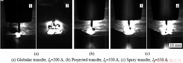
Fig. 1 Metal transfer forms of magnesium alloy using DC-PMIG welding (basic parameters: Ib=30 A, tp=3 ms, f=83 Hz)
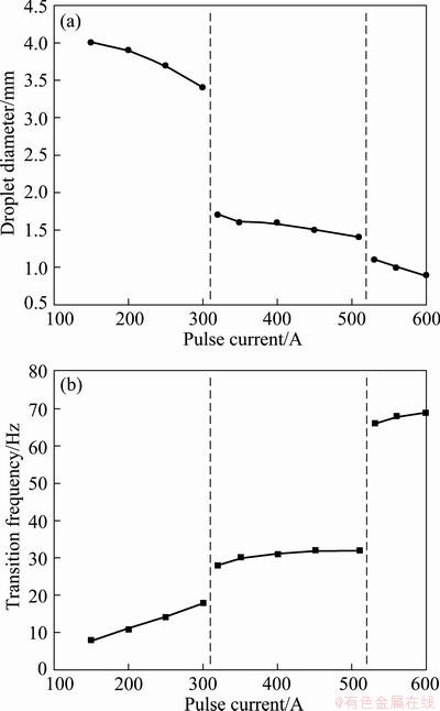
Fig. 2 Effects of pulse current on droplet diameter (a) and transition frequency (b) (Ib=30 A, tp=2 ms, f=83 Hz)
The relationship between droplet diameter (d), transition frequency (N) and Ip is shown in Fig. 2. d is the average diameter of the largest and smallest droplet after breaking away from wires. N is the total number of the droplets which have transferred into the weld pool per second. Figure 2(a) shows that d decreases with the increase of Ip, and the decreasing rate is highest when Ip=310 A and Ip=520 A. N increases with the increase of Ip, as shown in Fig. 2(b), and the increasing rate is highest when Ip=310 A and Ip=520 A. The reason is that the mode of metal transfer is globular transfer when Ip<310 A. Therefore, the average diameter of droplets is large and the metal transfer frequency is low. For DC-PMIG welding, droplets start to transfer generally when the Ip stage starts. Plasma fluid force in this stage increases with the increase of Ip, resulting in an easier transition of droplets, a higher N and a smaller d. The mode of metal transfer transforms into the projected transfer when Ip increases to 310 A. At the moment, d rapidly decreases to the diameter of filler wire, and N increases fast. When Ip increases to 520 A, the mode of metal transfer transforms from the projected transfer into the spray transfer. The mode of multiple droplets per pulse is realized by a strong auxo-action of plasma fluid force. It means several droplets would transfer in one stage of Ip. Therefore, d rapidly decreases and N swiftly increases when Ip=520 A. The pulse energy (Wp) at the point Ip=520 A is calculated as about 31 J when the pulse voltage (Up) is 30 V, Ip=520 A, tp=2 ms, according to Eq. (1). On the condition of base parameters in Fig. 2, when Ip=350 A, d=1.6 mm, N=30 Hz, Ua=21.3 V, Ia=104 A, vw=5.50 m/min, the linear energy of filler wire (Q) is calculated as 242 J/cm according to Eq. (2). When Ip=600 A, d=0.9 mm, N=69 Hz, Ua=21.6 V, Ia=126 A, ��w=6.05 m/min, Q is calculated as 270 J/cm. The stable welding process with few spatters can be realized when Ip is 350-600 A, d is 1.6-0.9 mm, N is 30-69 Hz and Q is 242-270 J/cm.
Wp=UpIptp/1000 (1)
where Wp is the pulse heat input per arc period, Up is the pulse voltage per arc period, Ip is the pulse current per arc period and tp is the pulse duration.
Q=0.6UaIa/vw (2)
where Q is the welding heat input to filler wire per unit length, Ua is the average voltage, Ia is the average current and ��w is the wire feeding speed.
The relationship between d, N and tp is shown in Fig. 3. d is in inverse proportion to tp and sharply decreases when tp=3 ms as shown in Fig. 3(a). N is in proportion to tp and sharply increases when tp=3 ms as shown in Fig. 3(b). The results show that the mode of metal transfer is the projected transfer when Ip=350 A and tp<3 ms. Metal transfer is accelerated by the plasma fluid force in the stage of Ip with the increase of tp, resulting in a decreasing droplet size. The mode of metal transfer changes into spray transfer when tp increases to 3 ms, and therewith d rapidly decreases and N increases fast. Wp at the moment is calculated as about 32 J when Up=30.5 V, Ip=350 A, tp=3 ms, which is consistent with the result of 31 J above. In addition, spray transfer mode was not observed in the experiments when Ip<350 A. The results show that the transition form from the projected transfer to the spray transfer can be realized when Ip>350 A and Wp>31 J. On the condition of base parameters in Fig. 3, d=1.6 mm, N=30 Hz, Ua=21.3 V, Ia=104 A, ��w=5.50 m/min and Q=242 J/cm when tp=2 ms; when tp=6 ms, d=0.9 mm, N=69 Hz, Ua=25.2 V, Ia=146 A, ��w=8.15 m/min and Q=271 J/cm. The stable welding process with few spatters can be realized when tp is 2-6 ms, d is 1.6-0.9 mm, N is 30-69 Hz and Q is 242-271 J/cm. This ranges of d, N and Q fit with the stable scopes of d, N and Q above when Ip is 350-600 A. In conclusion, high-quality joints with few spatters can be obtained in modes of projected transfer and spray transfer when Q is 242-271 J/cm, d is 1.6-0.9 mm and N is 30-69 Hz.
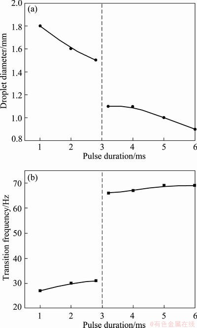
Fig. 3 Effects of pulse duration on droplet diameter (a) and transition frequency (b) (Ib=30 A, Ip=350 A, tb=10 ms)
The relationship between d, N and base current (Ib) is shown in Fig. 4. The corresponding relationship between droplet shape and current waveform is shown in Fig. 5. Figure 4(a) shows that d increases firstly and then decreases with the increase of Ib, and the turning point is nearby Ib=80 A where d rapidly increases. N increases with the increase of Ib, as shown in Fig. 4(b), also the increasing rate is highest nearby the point Ib=80 A. On the condition of the base parameters in Fig. 4, the mode is projected transfer when Ib<80 A. In the stage of base current, the plasma fluid force can��t meet the condition of droplet transfer, although it increases with the increase of Ib. The droplets still transfer in the stage of Ip as shown in Fig. 5(a). The fusion quantity of filler wire increases with the increase of Ib, leading to the increase of d and the relatively unchanged N. When Ib increases to 80 A, both the force and heat accumulation satisfy the condition of metal transfer, and droplets start to transfer in the stage of Ib as shown in Fig. 5(b). The mode of metal transfer in this stage is equivalent to globular transfer with a large droplet size because of the low current of this moment. Therefore, metal transfer form is the mixture mode of globular transfer and projected transfer when Ib>80 A. Not only the average size of droplets but also the metal transfer frequency substantially increases because metal transfer occurs in both the stage of Ip and Ib. Later, both of the plasma fluid force and heat accumulation increase with the continous increase of Ib, which results in a smaller droplet size and an increasing number of the droplets transferring in the stage of Ib.
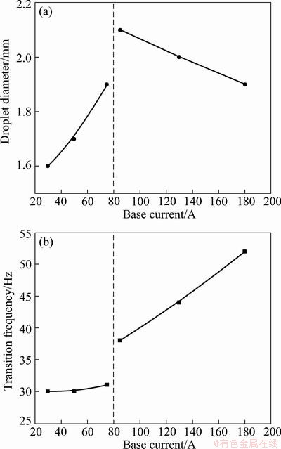
Fig. 4 Effects of base current on droplet diameter (a) and transition frequency (b) (Ip=350 A, tp=2 ms, f=83 Hz)
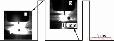
Fig. 5 Corresponding relationship between droplet shape and current waveform
3.2 Weld appearances and section shapes of welding joints
Figure 6 shows the weld appearances of the plates with different thicknesses. Projected transfer form was adopted for the butt welds of 3 mm-thickness plates. The face of weld is shapely with moderate fusion width and few spatters shown in Fig. 6(a). Continuous appearance of the back with proper weld reinforcement is observed in Fig. 6(b). Spray transfer form was adopted for the butt welds of 8 mm thickness plates. As shown in Figs. 6(c) and (d), the face of weld is homogeneous and continuous with dense and regular weld ripple, and the back is well fused.
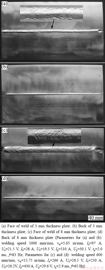
Fig. 6 Weld appearances of plates with different thicknesses
3.3 Microstructures and mechanical properties of weld beads
Figure 7 shows the microstructures of weld bead and base metal observed by optical microscope. Figure 7(a) shows that the grain size of base metal is 10-30 ��m, and the grain size of weld bead is half that of base metal, 8-15 ��m. It reveals that the microstructure of weld bead is refined. The grains size in HAZ is 20-50 ��m and the width of HAZ is 100-120 ��m as shown in Figs. 7(a) and (b). HAZ gradually widens from top to bottom along the fusion line, which illustrates that the bottom of weld bead has been most seriously affected by heat accumulation. The grain size of FZ is obviously smaller than that of HAZ or base metal, and the microstructures of FZ are uniform. Compared with Fig. 7(a), the width of HAZ of 8 mm-thickness plates in Fig. 7(b) is greater than that of 3 mm-thickness plates because of the larger welding heat input to the thick plate. As shown in Figs. 7(a) and (b), the precipitated phases in the weld bead are more than those in base metal. The precipitated phases mostly dispersing at grain boundary increase by degrees from base metal (BM) to heat affected zone (HAZ) to fusion zone (FZ), which is related to the heat cycle and resolidification. The contrast between Figs. 7(c) and (d) proves that the degree of segregation of precipitated phase at grain boundary of 3 mm-thickness plates is more serious than that of 8 mm-thickness plates. It should be attributed to the faster cooling rate and lower heat input for thin plates, which makes an insufficient diffusion of elements in solid solution and a higher degree of segregation of solute elements.
Figure 8 shows the macroscopic fracture modes of standard tensile specimens. Table 3 lists the mechanical properties of base metals and weld beads. The results show that the average ultimate tensile strength of weld beads is 94.2% of that of the base metal, and the average elongation of weld beads is 58.2% of that of the base metal. The macroscopic fracture mode of welding joint is similar to that of the base metal, shear fracture at a 45�� angle to drawing direction. It reveals that sufficient plastic deformation has occurred at the weld beads before they break. The fractures of weld beads all occur in FZ, which proves that FZ is weakest in weld bead, not HAZ. The reason is that the grains in HAZ grow not obviously compared with those in base metal. In addition, tiny pores or inclusions may exist in FZ where the fractures of weld beads easily occur.
Table 3 Mechanical properties of base metals and weld beads
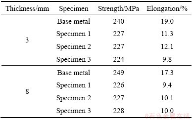
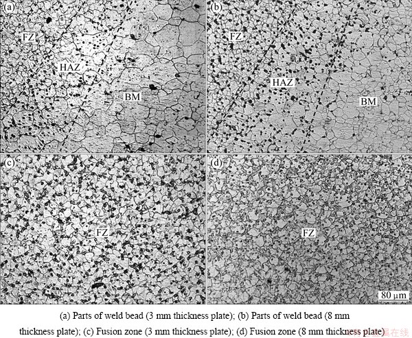
Fig. 7 OM microstructures of weld bead and base metal
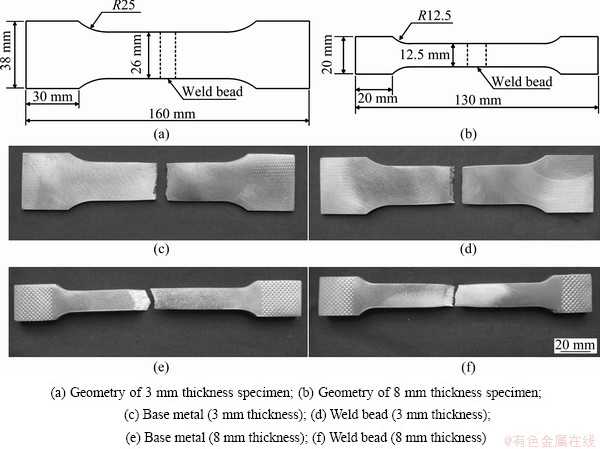
Fig. 8 Macroscopic fractures of specimens
4 Conclusions
1) The metal transfer form of magnesium alloy using DC-PMIG welding is realized in modes of globular transfer, projected transfer and spray transfer. Spatters with large size are produced in globular transfer form, and high-quality joints with few spatters can be obtained in the modes of projected transfer and spray transfer when Q is 242-271 J/cm, d is 1.6-0.9 mm and N is 30-69 Hz.
2) Within a certain range, droplet diameter (d) is in inverse proportion to Ip and tp, increasing firstly and then decreasing with the increase of Ib, and transition frequency (N) is in proportion to Ip, tp and Ib.
3) The grains in FZ are smaller in size and the grains in HAZ grow not obviously compared with those in base metal. The average ultimate tensile strength of weld beads is 94.2% of that of base metals, and the average elongation of weld beads is 58.2% of that of base metals.
References
[1] BROWN R E. Magnesium alloys and their applications [J]. Light Metal Age, 2001, 59(5-6): 54-56.
[2] ZHAO Li-ming, ZHANG Zhao-dong. Effect of Zn alloy interlayer on interface microstructure and strength of diffusion-bonded Mg-Al joints [J]. Scripta Materialia, 2008, 58(4): 283-286.
[3] YU Si-rong, CHEN Xian-jun, HUANG Zhi-qiu, LIU Yao-hui. Microstructure and mechanical properties of friction stir welding of AZ31B magnesium alloy added with cerium [J]. Journal of Rare Earths, 2010, 28(2): 316-320.
[4] CHI C T, CHAO C G, LIU T F, WANG C C. Relational analysis between parameters and defects for electron beam welding of AZ-series magnesium alloys [J]. Vacuum, 2008, 82(11): 1177-1182.
[5] QUAN Y J, CHEN Z H, GONG X S, YU Z H. Effects of heat input on microstructure and tensile properties of laser welded magnesium alloy AZ31 [J]. Materials Characterization, 2008, 59(10): 1491-1497.
[6] ZHANG Zhao-dong, ZHANG Fang. Spectral analysis of welding plasma of magnesium alloy using flux coated wire [J]. Materials Transactions, 2009, 50(8): 1909-1914.
[7] SONG Gang, LUO Zhi-min. The influence of laser pulse waveform on laser�CTIG hybrid welding of AZ31B magnesium alloy [J]. Optics and Lasers in Engineering, 2011, 49(1): 82-88.
[8] RETHMEIER M, KLEINPETER B, WOHLFAHRT H. MIG welding of magnesium alloys metallographic aspects [J]. Welding in the World, 2004, 48(3): 28-33.
[9] UEYAMA T, NAKATA K. Pulsed MIG welding of magnesium alloy [J]. Journal of Light Metal Welding & Construction, 2004, 42(5): 203-213. (in Japanese)
[10] GAO Ming, ZENG Xiao-yan, TAN Bing, FENG Jie-cai. Study of laser MIG hybrid welded AZ31 magnesium alloy [J]. Science and Technology of Welding and Joining, 2009, 14(4): 274-281.
[11] SONG Gang, WANG Peng. Pulsed MIG welding of AZ31B magnesium alloy [J]. Materials Science and Technology, 2011, 27(2): 518-524.
[12] SONG Gang, WANG Peng, LIU Li-ming. Study on ac-PMIG welding of AZ31B magnesium alloy [J]. Science and Technology of Welding and Joining, 2010, 15(3): 219-225.
[13] SONG Gang, WANG Cong, LIU Li-ming. Study on the behavior and mechanism of welding spatter of pulsed MIG welding of magnesium alloy [J]. Machinery Design and Manufacture, 2010, 3(9): 88-90.
[14] JIA Chang-shen, XIAO Ke-min, YIN Xian-qing. The plasmas flow force of welding arc [J]. Journal of Xi'an Jiaotong University, 1994, 28(1): 23-28. (in Chinese)
[15] ANDO K, HASEGAWA M. Welding arc phenomena [M]. Beijing: China Machine Press, 1985: 408. (in Chinese)
[16] LIU Li-ming, WANG Cong. Effect of low-power YAG laser on welding characteristics of pulsed MIG welding of magnesium alloy [C]//ZHONG Zhi-hua. Proceedings of the 9th International Conference on Frontiers of Design and Manufacturing. Changsha: Hunan University, 2010: 78-82.
AZ31Bþ�Ͻ�ֱ������MIG��������
���������������� ��
����������ѧ ���Ͽ�ѧ�빤��ѧԺ������ʡ�Ƚ����Ӽ����ص�ʵ���ң����� 116024
ժ Ҫ������ֱ������MIG(DC-PMIG)���ӹ��ռ�ֱ��Ϊ1.6 mm��þ�Ͻ�˿�����������3 mm��8 mm��ȵ�AZ31Bþ�Ͻӽ�ͷ���о�þ�Ͻ�DC-PMIG�����۵ι�����Ϊ�����ơ��ȶ����ӹ��̵IJ�����Χ����֯����ѧ���ܡ����������þ�Ͻ�DC-PMIG���ܹ�ʵ�ֵ��۵ι��ɷ�ʽ��3�֣��ֱ�Ϊ��ι��ɡ���ι��ɡ��������ɡ���ι��ɻ�����ߴ�ϴ�ĺ��ӷɽ�����������ι��ɺ��������ɣ��Һ�˿������Ϊ242~271 J/cm���۵γߴ�Ϊ1.6~0.9 mm���۵ι���Ƶ��Ϊ30~69 Hzʱ���ܹ���ú��ӷɽ����ٵĸ�������ͷ�����ӽ�ͷ���������ǿ��Ϊĸ�ĵ�94.6%��
�ؼ��ʣ�AZ31Bþ�Ͻ�ֱ������MIG�����۵ι��ɣ����ӷɽ�
(Edited by Sai-qian YUAN)
Foundation item: Project (IRT1008) supported by Changjiang Scholars and Innovative Research Team in University, China; Project (51005035) supported by the National Natural Science Foundation of China; Project (51025520) supported by the National Natural Science Funds for Distinguished Young Scholar, China
Corresponding author: Li-ming LIU; Tel/Fax: +86-411-84707817; E-mail: liulm@dlut.edu.cn
DOI: 10.1016/S1003-6326(13)62463-2

