Semi-active control of a vehicle suspension using magneto-rheological damper
来源期刊:中南大学学报(英文版)2012年第7期
论文作者:蒋学争 王炅 胡红生
文章页码:1839 - 1845
Key words:magneto-rheological damper; vehicle suspension; semi-active control
Abstract: A semi-active magneto-rheological (MR) damper was experimentally investigated and compared to an original equipment manufacturer (OEM) damper for a passenger vehicle, by using a quarter car models. A full-scale two-degree-of-freedom quarter car experimental set-up was constructed to study the vehicle suspension. On-off skyhook controller and Fuzzy-Lyapunov skyhook controller (FLSC) were employed to control the input current for MR damper so as to achieve the desired damping force. Tests were done to evaluate the ability of MR damper for controlling vehicle vibration. Test results show that the semi-active MR vehicle suspension vibration control system is feasible. In comparison with OEM damper, on-off and FLSC controlled MR dampers can effectively reduce the acceleration of vehicle sprung mass by about 15% and 24%, respectively.
J. Cent. South Univ. (2012) 19: 1839-1845
DOI: 10.1007/s11771-012-1217-9![]()
JIANG Xue-zheng(蒋学争)1, WANG Jiong(王炅)1, HU Hong-sheng(胡红生)2
1. School of Mechanical Engineering, Nanjing University of Science and Technology, Nanjing 210094, China;
2. Faculty of Mechanical and Electrical Engineering, Jiaxing University, Jiaxing 314001, China
? Central South University Press and Springer-Verlag Berlin Heidelberg 2012
Abstract: A semi-active magneto-rheological (MR) damper was experimentally investigated and compared to an original equipment manufacturer (OEM) damper for a passenger vehicle, by using a quarter car models. A full-scale two-degree-of-freedom quarter car experimental set-up was constructed to study the vehicle suspension. On-off skyhook controller and Fuzzy-Lyapunov skyhook controller (FLSC) were employed to control the input current for MR damper so as to achieve the desired damping force. Tests were done to evaluate the ability of MR damper for controlling vehicle vibration. Test results show that the semi-active MR vehicle suspension vibration control system is feasible. In comparison with OEM damper, on-off and FLSC controlled MR dampers can effectively reduce the acceleration of vehicle sprung mass by about 15% and 24%, respectively.
Key words: magneto-rheological damper; vehicle suspension; semi-active control
1 Introduction
Usually, the design of a vehicle suspension system requires a trade-off between vehicle stability and ride comfort. Vehicle suspension systems support the weight of the vehicle, provide directional control during handing maneuvers and should have the ability to decrease the vibration subjected to passengers and payload created by road disturbances. A typical vehicle suspension is made up of two components: a spring and a hydraulic damper [1]. The suspension stores energy in the spring and dissipates energy through the damper. A large amount of energy dissipation usually causes harsh or uncomfortable ride, although it is beneficial for vehicle stability. The need to reduce the effects of this compromise has given rise to several new advancements in automotive suspensions. Controllable suspension system is considered to be a promising way of minimizing the compromise between the ride quality and the handling of the vehicle [2].
Controllable suspension systems can be classified into active and semi-active suspension systems. If the damper in vehicle suspensions is replaced with a force actuator, the suspension becomes a fully active suspension system [3-5]. However, hindered by its complexity and high cost, active controllable suspension systems have not been used commonly in vehicle applications [6]. It has been proved that the semi-active suspensions can provide the same performance as the fully active controlled suspension systems while requiring lower power consumption and offering a simple design. In a semi-active suspension, the passive damper is replaced with a semi-active damper [7-9]. A semi-active damper is capable of changing its damping characteristics [10].
In recent years, magneto-rheological (MR) fluid, which has the ability to reversibly change its rheological properties (elasticity, plasticity and viscosity) with the application of a magnetic field, has been widely used in the area of structural vibration control [11-14]. And the MR damper using MR fluid instead of conventional oil as working liquid becomes one of the most promising devices for the semi-active vibration control of the vehicle suspensions [15-18].
In this work, a semi-active suspension system based on MR dampers was used to control the vibration of the vehicle. A new MR damper which fits for vehicle use was designed and manufactured. The level of the damping force of this MR damper at various applied currents was experimentally evaluated and identified. A full-scale, two-degree-of-freedom (DOF) quarter-car- model of the vehicle was designed and built to study the performance of the MR semi-active vehicle suspension system. On-off skyhook control strategy and Fuzzy- Lyapunov skyhook control strategy were employed to control the current in MR damper and achieve the desired damping force to control the vibration of vehicle suspensions. Then, a series of tests were done to evaluate the feasibility of using MR damper system.
2 MR damper
The MR damper is an intelligent device whose damping force can be changed by altering the magnetic density in the magnetic coils, leading to the continuous change of viscosity in the piston gap. The schematic configuration of the proposed MR damper used in this work is shown in Fig. 1. The MR damper is a twin-tube damper and has two concentric tubes connected with a valve. The valve allows for MR fluid to flow from the inner to the outer tubes to adjust the piston displacement. There is a pressed gas chamber between the outer and inner tubes to compensate the volume change caused by the movement of piston rod. A small clearance (gap) between the piston and the inner cylinder provides the means for the MR fluid to pass through as the piston moves within the inner cylinder. The electromagnetic coil is used to generate magnetic field to control MR fluids. When the MR fluid is activated by a different magnetic flux densities, it offers a different amount of resistance to the motion of the piston, thus providing different damping forces. The larger the magnetic flux density is, the higher the fluid resistance to the piston and the larger the damping force. The magnetic flux density is controlled by the amount of electric current supplied to the electromagnetic coil. In order to simplify the analysis of the MR damper, it is assumed that the MR fluid is incompressible and the pressure in one chamber is uniformly distributed. Furthermore, it is assumed that fluid inertia, which is caused by abrupt acceleration of the damper, is negligible. Thus, the damping force of the MR damper can be expressed as follows:
![]() (1)
(1)
where Fη is the viscous damping, Fτ is the coulomb damping force due to MR fluids activation by magnetic
field, Ff is the friction force, ![]() ,
, ![]() ,
, ![]() , Cf is the
, Cf is the
coefficient of sliding friction, k1 is the plastic flow index, ρ is the density of the MR fluid, A0 is the transect area of the damping channel, AT is the working area of the piston, L is the length of the damping channel, μ is the velocity of the fluid in the gap, g is the thickness of the gap, ω is the average perimeter of the gap, τy is the yield stress of the MR fluid and v is the velocity of the piston.
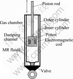
Fig. 1 Cross-section of configuration for MR damper
The size and the level of required damping force adopted in this work are chosen on the basis of conventional passive oil damper for a middle-size passenger car. The outer diameter of the inner cylinder is chosen as 27.8 mm. The length of the damping channel and the gap between piston and inner cylinder are 10 mm and 0.4 mm, respectively. And the number of electromagnetic coil turns is 234 and the diameter of the copper coil is 0.8 mm. Furthermore, fluid (MRF-140CG) in the MR damper is chosen from the Lord Corporation. The photos of the fabricated MR damper are shown in Fig. 2.
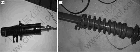
Fig. 2 Photos of fabricated MR damper
After comparative analysis, Fig. 3 presents the damping force with respect to the piston displacement at various input-currents in electromagnetic coil (experimental condition: 10 mm amplitude and 1 Hz frequency sinusoidal vibration excitation). It is clearly observed that the maximum damping force is increased as the input-current increases. As a specific case, the damping force of 200 N under the condition of 0 A input-current is increased up to 1 400 N by applying the input-current of 1.6 A. It is also seen that the measured outcome agrees fairly well with the theoretical design that the damping force is proportional to the input-current value. This directly advocates the validity of the proposed function of the MR damper, that is, the damping force of the MR damper can be semi-actively controlled by the input-current in electromagnetic coil of MR damper.
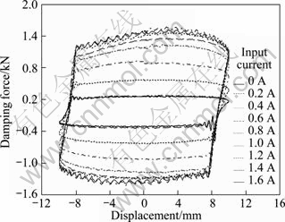
Fig. 3 Damping force characteristics of MR damper
3 Quarter-car model of vehicle with MR damper
The MR quarter-car-model of vehicle is shown in Fig. 4. In this model, tire-damping force is neglected, while tire bounce (lost road contact) is considered. The MR damper is mounted between the sprung mass, ms, and the unsprung mass, mu. ks and ku represent the suspension spring stiffness and the tire stiffness, respectively. xs and xu are the displacements of the sprung mass and unsprung mass, respectively. The road input is xr. The equations of motion of the system excited by the road profile can be expressed as follows:
![]() (2)
(2)
![]() (3)
(3)
where F is the change in the spring force from the static equilibrium condition. Fe is the total damping force of the MR damper and can be written as follows:
![]() (4)
(4)
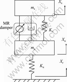
Fig. 4 Quarter-car model for semi-active MR vehicle suspension
As shown in Eq. (1), the output damping force of MR damper consists of viscous damping force, friction force, and coulomb damping force. The viscous damping force and friction force are present even in the absence of the magnetic field. The coulomb damping force is the controllable force component and can be varied by different input-currents. When no input-current is applied to the MR damper, there is also viscous damping to control the vibration. So, the MR damper is considered to be fail-safe and can provide vibration control with or without a control system. At the same time, in order to semi-actively control the vehicle suspension, a control algorithm should be utilized to determine the appropriate magnetic field required to generate necessary coulomb damping force.
4 Control strategy
In this work, on-off skyhook control and Fuzzy-Lyapunov skyhook control (FLSC) algorithm are utilized to control the MR damper in order to generate necessary damping force. The FLSC combines the features of both Lyapunov control and on-off skyhook control and is designed based on the skyhook principle and a fuzzy logic control theory. In order to develop FLSC algorithm for semi-active vehicle suspensions use, it is firstly required to study the properties of on-off control algorithm.
4.1 On-off skyhook control
In skyhook control, a fictitious damper is connected to inertial reference in the sky. The reason for this representation is only for defining the mathematical model of the control algorithm. Obviously, there is no fixed point for the damper. Figure 5 shows the sky-controlled damper used in the quarter car suspension model.
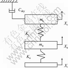
Fig. 5 Skyhook control in quarter vehicle suspension
The control condition criterion for the on-off skyhook algorithm is the product of the absolute velocity of the sprung mass relative to ground ![]() and the relative velocity between sprung and unsprung mass
and the relative velocity between sprung and unsprung mass![]() . To simplify the on-off skyhook control design, it can be usually expressed as an on-off format:
. To simplify the on-off skyhook control design, it can be usually expressed as an on-off format:
![]() (5)
(5)
where Fc is a constant damping force of the MR damper when the MR damper is activated by input-current.
So, the required input-current applied to the MR damper in on-off skyhook control strategy can be expressed as
![]() (6)
(6)
where ion is the input-current applied to the MR damper, which is determined by the relationship between the absolute velocity ![]() and the relative velocity
and the relative velocity![]() .
.
4.2 Fuzzy-Lyapunov skyhook control (FLSC)
The basic principle of FLSC can be indicated as follows. Firstly, skyhook control algorithm is used to build the reference model of the quarter-car suspension, and then Lyapunov control algorithm based on fuzzy algorithm to construct control-strategy is used to adjust the input-current in MR damper in order to control vehicle suspension tracking the reference model. Figure 6 illustrates the FLSC used in quarter car model.
After defining vector![]() as the state vector of the system, the state equation of the vehicle body can be expressed as
as the state vector of the system, the state equation of the vehicle body can be expressed as
![]() (7)
(7)
where  ,
,  ,
,  ,
,
and w is the disturbing force acting upon the sprung mass including the error of the control force.
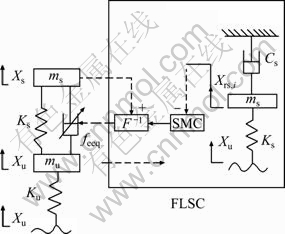
Fig. 6 FLSC in quarter car model
Taking ![]() as the state vector of the reference model, the state equation of the reference model can be written as
as the state vector of the reference model, the state equation of the reference model can be written as
![]() (8)
(8)
where , and Cs is the desired skyhook damping coefficient.
Defining vector ![]() as tracking error and
as tracking error and ![]() , combining Eqs. (7) and (8) yields
, combining Eqs. (7) and (8) yields
![]() (9)
(9)
where


So, the constructor function can be expressed as
![]() (10)
(10)
where R1 and R2 are constant parameters.
Considering Lyapunov equation ![]()
![]() , there is
, there is
![]() (11)
(11)
According to Eq. (11), it can be seen that: if R1>0 and R2>0, then dV/dt<0; if (e, ?)→∞, then V(e, ?)→∞.
Based on Lyapunov stability theory, it is known that the constructor function is gradually stable in a large numerical range.
It is supposed that the disturbing force equals zero, so the damping force of the MR damper based on Lyapunov stability theory can be written as
 (12)
(12)
Combining the features of both the skyhook control and Lyapunov stability theory, the FLSC is proposed as
![]() (13)
(13)
And the required electric current applied to the MR damper in FLSC strategy takes the following form:
![]() (14)
(14)
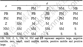
In Eq. (13), Q is defined by the fuzzy control rule, as given in Table 1, and the aim of this control strategy is to minimize the tracking error e and ?. In Table 1, e and ? are input parameters, and based on the properties of MR damper and control target, the value of e is within the scope of [-0.4, 0.4], the value of ? is within the scope of [-6, 6], and the value of Q is within the scope of [1.5, 2].
Table 1 Fuzzy control rule
5 Test analysis
5.1 Experimental setup
The experimental setup utilizing a full-scale passenger quarter-vehicle-model was constructed to evaluate the performance of the OEM damper and the semi-active MR damper. The parameters of the model based on this middle-size passenger are: ms=453.6 kg, mu=45.4 kg, ks=40 288 N/m, ku=157 120 N/m, Cs= 4 000 N・s/m, R1=16, R2=150. A PA-20-Z servo-hydraulic system was used to provide the input road profile. The actuator of the hydraulic unit is mounted to a plate, which excites the masses and the suspension system shown in Fig. 7.
A plastic plate was used to model the rear tire stiffness (ku) and mounted between the input actuator and unsprung mass. Six steel plates were used to represent the mass of the components located under the suspension system. The MR damper system was used to represent the suspension system and was located between the sprung and unsprung masses. A simple linear slider system consisting of ball bearing and steel shafts was used to constrain the lateral motion of the setup. A load cell was located between the input actuator and the plastic plate in order to measure the suspension system mass and the friction of the slide system. A cable extension linear variable differential transducer (LVDT) was mounted on the sprung mass in order to measure both displacement and velocity of the vehicle body. Another LVDT was mounted between sprung and unsprung mass to measure the relative displacement and velocity. The velocity data were used as feedback to control system during MR damper control evaluation. An accelerometer was mounted on the sprung mass to measure the absolute acceleration of the vehicle body. A data acquisition system (PXI-4472B) was used with LabVIEW software to record the acceleration data and control the MR damper.
5.2 Experimental results
The rough road profile at a vehicle speed of 72 km/h shown in Fig. 8 was selected as input for the experimental evaluation. Simple road profiles were used in order to study the performance of the MR and OEM dampers in controlling the vehicle suspension vibration. The acceleration transmissibility result of sprung mass was presented for both suspension systems using the MR and OEM dampers under simple harmonic motion. The acceleration power spectral density (PSD) of sprung mass was investigated under random input. The root mean square (RMS) of acceleration for sprung was presented. The MR damper experimental results were compared with the OEM damper results, as shown in Figs. 9 and 10.
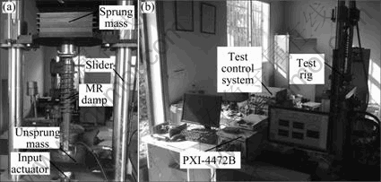
Fig. 7 Experimental setup
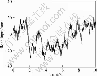
Fig. 8 Rough road input motion for experimental evaluation
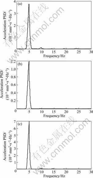
Fig. 9 Acceleration PSD of sprung mass under different dampers control: (a) OEM damper; (b) On-off skyhook controlled MR damper; (c) FLSC controlled MR damper
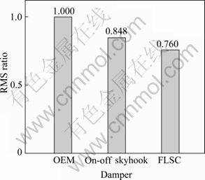
Fig. 10 Acceleration RMS of sprung mass
Figure 9 shows acceleration PSD of the sprung mass under the OEM and MR damper for the same random motion input. Based on the results shown in Fig. 9, the peak PSD value of acceleration for OEM is much higher than that for on-off and FLSC control system, which is about 2.5 times higher than on-off control and 5.5 times higher than FLSC control system. At the same time, the peak PSD value of acceleration for on-off control is also higher than FLSC by about 2 times. As peak acceleration increases, the ride quality of vehicle decreases. In other words, FLSC strategy controlled MR damper system can provide greater ride quality over on-off skyhook control system and OEM system.
Figure 10 presents the root mean square of the sprung mass acceleration. It is indicated that the performances of on-off and FLSC are comparable while OEM experiences about 15% and 24% decrease, respectively, in the RMS ratio, and the FLSC makes best control of the sprung vibration again. So, the ride quality of vehicle can also be improved by utilizing the MR damper with on-off and FLSC control strategy.
6 Conclusions
1) The acceleration of the vehicle body can be effectively reduced by replacing the OEM damper with both the on-off and FLSC controlled MR damper.
2) The vehicle ride quality can also be improved by using semi-active MR damper system to control the vibration of vehicle.
3) The FLSC strategy can offer better acceleration performance as compared to the on-off skyhook control strategy and do best in controlling the vehicle vibration. So, it is possible to use semi-active MR damper to control the vehicle vibration and give a better ride for people to drive. In other words, it can get a good trade-off between vehicle stability and ride comfort.
References
[1] NAUDE A F, SNYMAN J A. Optimisation of road vehicle passive suspension systems [J]. Applied Mathematical Modelling, 2003, 27: 249-274.
[2] NAGAI M, MORAN A, TAMURA Y, KOIZUMI S. Identification and control of nonlinear active pneumatic suspension for railway vehicles, using neural networks [J]. Control Eng Practice, 1997, 5(8): 1137-1144.
[3] YAGIZ N, HACIOGLU Y. Backstepping control of a vehicle with active suspensions [J]. Control Eng Practic, 2008, 16: 1457-1467.
[4] PRIYANDOKO G, MAILAH M, JAMALUDDIN H. Vehicle active suspension system using skyhook adaptive neuro active force control [J]. Mechanical Systems and Signal Processing, 2009, 23: 855-868.
[5] JONASSON M, ROOS F. Design and evaluation of an active electromechanical wheel suspension system [J]. Mechatronics, 2008, 18: 218-230.
[6] SUNG K G, HAN Young-min, CHO J W, CHOI S B. Vibration control of vehicle ER suspension system using fuzzy moving sliding mode controller [J]. J Sound Vib, 2008, 311: 1004-1019.
[7] RAO M V C, PRAHLAD V. A tunable fuzzy logic controller for vehicle-active suspension systems [J]. Fuzzy Sets and Systems, 1997, 85: 11-21.
[8] SOLOMON U, PADMANABHAM C. Semi-active hydro-gas suspension system for a tracked vehicle [J]. J Terramechanics, 2011, 48: 225-239.
[9] GORDON T. Non-linear optimal control of a semi-active vehicle suspension system [J]. Chaos Solitons & Fractals, 1995, 5(9): 1603-1617.
[10] GUGLIELMINE E, KEVIN A E. A controlled friction damper for vehicle applications [J]. Control Eng Pract, 2004, 12: 431-443.
[11] WANG Hong-jun, TIAN Ai-ling, TANG Qian, CHEN Zhi-li, LIU Bing-cai. Research on rheological property of magnetorheological fluid [C]// 3rd International Symp on Advanced Optical Manufacture and Testing Technology: Advanced Optical Manufacturing Technologies Proc of SPIE. Chengdu, China: 2007, 672230: 1-5.
[12] KUZHIR P, LOPEZ-LOPEZ M T, BOSSIS G. Abrupt contraction flow of magnetorheological fluids [J]. Phys Fluids, 2009, 21(053101): 1-13.
[13] MIAO Chun-lin, KIRK M B, ANNE E M, SHAI N S, JESSICA E D, STEPHEN D J. Magnetorheological fluid template for basic studies of mechanical-chemical effects during polishing [C]// Optical Manufacturing and Testing VII Proc of SPIE. San Diego, California, USA: 2007, 667110: 1-11.
[14] CHO S W, JUNG H J, LEE L W. Smart passive system based on magnetorheological damper [J]. Smart Materials and Structures, 2005, 15(4): 707-714.
[15] YAO G Z, YAP F F, CHEN G, LI W H, YEO S H. MR damper and its application for semi-active control of vehicle suspension system [J]. Mechatronics, 2002, 12: 963-973.
[16] GEORGIOS T, CHARLES W S, EMANUELE E. Hybrid balance control of a magnetorheological truck suspension [J]. J Sound Vib, 2008, 317: 514-536.
[17] YU Miao, DONG Xin-min, CHOI S B, LIAO Chang-rong. Human simulated intelligent control of vehicle suspension system with MR dampers [J]. J Sound Vib, 2009, 319: 753-767.
[18] POTTER J N, NEILD S A, WAGG D J. Quasi-active suspension design using magnetorheological dampers [J]. J Sound Vib, 2011, 330: 2201-2219.
(Edited by YANG Bing)
Foundation item: Project(51175265) supported by the National Natural Science Foundation of China; Project(CX10B_114Z) supported by Jiangsu College Graduate Research and Innovation Program, China; Project(BK2008415) supported by the Natural Science Foundation of Jiangsu Province, China; Project(Y1110313) supported by the Natural Science Foundation of Zhejiang Province, China
Received date: 2011-07-26; Accepted date: 2011-11-14
Corresponding author: WANG Jiong, Professor, PhD; Tel: +86-25-84315324; E-mail: wjiongz@mail.njust.edu.cn

