Localization system for mobile robot using scanning laser and ultrasonic measurement
来源期刊:中南大学学报(自然科学版)2011年第z1期
论文作者:刘凯 孙增圻 安斌
文章页码:441 - 447
Key words:mobile robot; localization; dead reckoning; scanning laser; ultrasonic measurement
Abstract: A low-cost, installation convenient, continuously accurate and multi-sensor based localization system for a mobile robot was introduced. A gyroscope based dead reckoning system was firstly employed to provide momentary but real-time heading and position information for the robot. Then, a novel scanning laser and ultrasonic absolute positioning system was developed to eliminate the accumulative error in dead reckoned robot heading and position. The robot has a fixed base station where the robot can recharge itself. A scanning laser and an ultrasonic transmitter were mounted on the base station to measure the robot’s angle and distance relative to it. Another scanning laser was mounted on the robot to measure the base station's relative angle in the robot’s frame. The base station and the robot were wirelessly connected through radio frequency (RF). This method was implemented on a lawn robot. Experimental results show that the lawn robot can work continuously for a long period of time within thirty meters away from the base station without losing its position.
LIU Kai(刘凯)1, SUN Zeng-qi(孙增圻)1, AN Bin(安斌)2
(1. Department of Computer Science & Technology, Tsinghua University, Beijing 100084, China;
2. School of Civil & Environment Engineering, University of Science & Technology Beijing, Beijing 100083, China)
Abstract: A low-cost, installation convenient, continuously accurate and multi-sensor based localization system for a mobile robot was introduced. A gyroscope based dead reckoning system was firstly employed to provide momentary but real-time heading and position information for the robot. Then, a novel scanning laser and ultrasonic absolute positioning system was developed to eliminate the accumulative error in dead reckoned robot heading and position. The robot has a fixed base station where the robot can recharge itself. A scanning laser and an ultrasonic transmitter were mounted on the base station to measure the robot’s angle and distance relative to it. Another scanning laser was mounted on the robot to measure the base station's relative angle in the robot’s frame. The base station and the robot were wirelessly connected through radio frequency (RF). This method was implemented on a lawn robot. Experimental results show that the lawn robot can work continuously for a long period of time within thirty meters away from the base station without losing its position.
Key words: mobile robot; localization; dead reckoning; scanning laser; ultrasonic measurement
CLC number: TP242.6 Document code: A Article ID: 1672-7207(2011)S1-0441-07
1 Introduction
The ability of locating itself in the environment is essential for a mobile robot to execute its commands. Localization is fundamental to subsequent tasks such as map building and collision-free path planning. Various methods have been developed by many researchers. A review on the mobile robot localization technologies can be found in Ref.[1]. Among those, odometry was widely used to determine the momentary position. Borenstein et al[2] improved the accuracy of odometry of one order of magnitude by measuring and correcting the robot’s systematic errors. However wheel slippage and ground roughness would cause fatal error in robot's heading measurement, which could later introduce significant position error. In order to improve the robot's heading accuracy as well as the dead reckoning accuracy, gyroscope was used and tested by many researchers[3-7]. The dead reckoning method using gyroscope can avoid the influence of wheel slippage and ground roughness on robot heading measurement, and hence provides more accurate momentary position and heading than odometry does. But low-cost gyroscope suffers from random drift over long time running. Dead reckoning is a relative localization method, and may suffer from unbounded accumulative errors. To compensate this, absolute method must be used. Triangulation using landmarks is a commonly adopted method[8-10]. To use artificial landmark triangulation, the position of each landmark must be known. This is not convenient when the robot's working environment is unstructured. To use natural landmark triangulation, an accurate map for the environment should be available. Often, to build a map of the robot’s environment is a tough task for users. Tsai[11] combined flux gate compass, rate-gyro and two encoders to get optimal estimate of robot heading, and combined the dead reckoning position estimate with ultrasonic range measurements to remove accumulated position errors, but the coverage of the ultrasonic transmitter was limited to a small area. And this method fails in the environment where the magnetic field of the earth is twisted. Vision-based localization and SLAM (Simultaneous Localization And Mapping) are regarded as key essentials for a real autonomous mobile robot and are widely researched in resent years[12-13]. But the computational complexity hinders their realistic application.
Our efforts focus on developing a simple, low-cost, continuously accurate and convenient method of mobile robot localization using multi-sensor. It is assumed that the mobile robot has a base station fixed to the ground where the robot can recharge itself. The robot’s position and heading are relative to the base station. The method’s novelty lies in the combination of scanning laser and ultrasonic measurement to construct an absolute localization system. A scanning laser and an ultrasonic transmitter were mounted on the base station to measure the robot’s angle and distance relative to it. Another scanning laser was mounted on the robot to measure the base station’s relative angle in the robot's frame. The base station and the robot are wirelessly connected through radio frequency (RF). Using the extended Kalman filter, the data of scanning laser and ultrasonic absolute positioning system were fused with the dead-reckoning system which utilizes a low-cost gyroscope. This method achieves the convenience that neither extra artificial landmark nor an accurate map of the environment is needed, and it is suitable to both structured and unstructured environment.
2 System configuration
The mechanical structure of our mobile robot is typical, which consists of two independently driven back wheels and a freely rotating front wheel. The robot has a DSP as its central controller. A low-cost and high drifting numerical MEMS gyroscope ADIS16255 was utilized in dead reckoning. Two optical incremental encoders were mounted on the driving motors to provide the odometry information of each wheel for the dead reckoning. Compass is not used for the reason that in some environments the magnetic field is twisted and it will lost its function or bring error heading information to the robot, especially when the magnetic field’s direction changes slowly from place to place.
Due to the wheel slippage, surface roughness and gyro drift, there is accumulative error in robot position estimation. So, an absolute positioning system is needed to compensate the accumulative error in dead reckoning system. To improve the convenience of installation, the base station was full used and no extra landmark was needed. According to polar coordinates system, to locate the robot, the angle and distance of the robot in the base station polar coordinates system should be known. A laser scanner with a high-resolution optical encoder was mounted on the base station to get the polar angle. An ultrasonic wave transmitter was attached to the scanning laser and rotates with it. Fig.1 shows the structure.
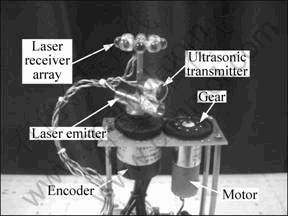
Fig.1 Assembling structure of scanning laser, ultrasonic transmitter and laser receiver array on base station
A laser receiver array and an ultrasonic wave receiver array were mounted on the robot. They can receive the laser and ultrasonic wave that comes from any direction from the base station. Fig.2 shows the structure.
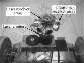
Fig.2 Assembling structure of laser receiver array, ultrasonic receiver array and laser emitter on robot
When the laser is received by the robot, it sends a RF signal to the base station to indicate that the robot is scanned by the base. Then the base station sends the angle of the scanning laser encoder to the robot and emits an ultrasonic wave pulse after that. Since the time delay from the RF transmitting to the ultrasonic wave sending is constant, the TOF (Time of fly) of the ultrasonic wave can be measured so as to obtain the distance from base station to the robot.
To compensate the angle drift of the low cost gyroscope, another scanning laser was mounted on the robot, and the laser’s direction was also measured by a high-resolution optical incremental encoder (Fig.2). The laser line emitted by the base station and the robot were modulated to different frequency to avoid mutual and sun light interruption. The base station also has a laser receiver array to receive the laser from the robot. When the robot laser is received by the base station, it sends a RF signal to the robot. The moment robot receives the signal from base station, the angle of the scanning laser encoder is read out. Together with the position of the base station and the robot, the robot heading can be calculated. And then fused with gyroscope information, the optimal robot heading is estimated.
A sketch of the scanning laser and ultrasonic absolute positioning system is shown in Fig.3.
3 Implementation
3.1 Dead reckoning system
When the robot is not scanned by the base station, it works in a dead reckoning mode. Tsai[11] used a multisensorial scheme fusing data from gyro, flux compass and two encoders to get an optimal estimate of the robot heading. But this method fails when the direction of earth magnetic field changes slowly from place to place. In this condition, the absolute difference between the compass heading and gyro heading is less than the selected threshold in every sampling period (0.5 s), and the error information in compass is fused in the robot heading. Gradually, the robot heading converges to the direction of magnetic which has been twisted. This is because the error model in compass measurement is not a discrete-time, zero-mean white Gaussian process when the magnetic field is slowly twisted. So in our system, the robot relative heading was measured by fusing information from gyro and two encoders, and later the relative heading was fused with scanning laser angle information when the base station is scanned by robot. Let θe(k) and θe(k-1) denote the robot heading angle estimated by using the information from two wheel encoders at time k and (k-1), so θe(k) can be calculated by
![]() (1)
(1)
where ?pr and ?pl denote the pulse increase of right encoder and left encoder from time (k-1) to time k. d denotes the distance between the driven wheels. cr and cl convert the encoder pulse to distance traveled by the right and left wheels in millimeter. In order to get the accurate value of cr and cl, the robot was manually driven to track along a straight line path for a distance l, and read the pulse increase pr and pl. The cr and cl can be calculated by cr=l/pr and cl=l/pl. Several measurements are needed to increase accuracy by calculating the average value of cr and cl. Measurement noise ne(k) is assumed to be a zero-mean white Gaussian process with variance ![]() .
.
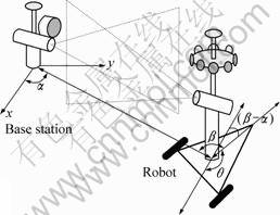
Fig.3 Sketch of scanning laser and ultrasonic absolute positioning system
Let θg(k) and θg(k-1) denote the robot heading angle estimated from gyroscope. For convenience, the equation of gyro heading measurement in Ref.[11] was rewritten here,
![]() (2)
(2)
where θ(t) is the gyro’s rotational rate. T is the integration period. The noise ng(k) is also assumed to be a zero-mean white Gaussian process with variance ![]() . According to Ref.[11], if the absolute difference between θe(k) and θg(k-1) is less than a selected threshold, the dead reckoning optimal robot heading estimated by fusing information from gyro and two encoders is
. According to Ref.[11], if the absolute difference between θe(k) and θg(k-1) is less than a selected threshold, the dead reckoning optimal robot heading estimated by fusing information from gyro and two encoders is
![]() (3)
(3)
otherwise, θd(k)=θg(k). After the fusing, let θe(k)=θg(k)= θd(k).
The gyro and encoder information updating period is 10 ms to provide the robot real time heading information which is needed in its real time control. θe(k) and θg(k) are fused every 0.5 s. It is called the fusing period. In between the fusing period, θd(k) equals to θg(k). If the fusing period is too small, the error between θe(k) and θg(k) ?will be constantly below the threshold even when wheel slippage occurs. Therefore, error information will be fused in the robot heading.
Next, the robot’s dead reckoned position (xd, yd) is updated every 10 ms by
![]() (4)
(4)
![]() (5)
(5)
where
![]() (6)
(6)
![]() (7)
(7)
3.2 Scanning laser and ultrasonic positioning system
The dead reckoning positioning system is relative and will suffer from unbounded accumulative error. Therefore, an absolute positioning system is needed to eliminate the accumulative error in robot heading and position in time. The scanning laser mounted on the base station scans the robot repeatedly. When the robot is scanned by the base station, it sends a RF signal. When the base station receives the RF signal, it sends the scanning laser angle α (shown in Fig.3) to the robot also through RF and then emits an ultrasonic wave pulse immediately. Let trf denote the moment when the radio frequency (which contains the scanning laser angle) is received by the robot, and tul denotes the moment when ultrasonic wave pulse is received by the robot. The radio signal travels in the air at light speed. So its flying time can be ignored, then the ultrasonic flying time is
![]() (8)
(8)
where t0 denotes the system’s constant time delay from the RF transmitting to the ultrasonic wave sending in base station and RF receiving delay in robot. As the sound speed is related to the density of air, there is a temperature sensor on the robot to compensate the sound speed variance. So, drb the distance between the robot and the base station) is measured. Accompany with the angle of the scanning laser, the robot’s absolute position (xa, ya)? in the frame of base station can be calculated by
![]() (9)
(9)
![]() (10)
(10)
If the distance between the dead reckoned position and the absolute position measured by scanning laser and ultrasonic positioning system is less than a selected threshold, the absolution position (xa, ya) is fused with the dead reckoning system by extended Kalman filter. Define X(k)=(x(k), y(k)), Xd(k)=(xd(k), yd(k)) and let K(k) denote the Kalman filter error gain at time k. The extend Kalman filter consists of the following steps:
1) The one step optimal prediction X(k|k-1) should be the dead reckoned position Xd(k) calculated by Eqns.(4)-(7). Thus,
![]() (11)
(11)
Its propagation error covariance matrix ![]() can be calculated by
can be calculated by
![]() (12)
(12)
where ![]() is the error covariance matrix of optimal estimate
is the error covariance matrix of optimal estimate ![]() at time k-1, and Q(k-1) is the diagonal covariance matrix of process noises.
at time k-1, and Q(k-1) is the diagonal covariance matrix of process noises.
2) Since the robot's position state X(k) can be all returned by the scanning laser and ultrasonic positioning system, the state transition matrix F(k+1, k) and observation matrix C(k) should be unit matrix, so K(k) is calculated by
![]() (13)
(13)
where R(k) denotes the diagonal covariance matrix of measurement noises.
3) Then we can get robot position's optimal estimate ![]() and update the error covariance matrix
and update the error covariance matrix ![]() using
using
![]() (14)
(14)
![]() (15)
(15)
where Xa(k) denotes the robot absolute position calculated by Eqns.(9) and (10) at time k, namely Xa(k)=(xa(k), ya(k)). After the fusing, let
![]() (16)
(16)
to eliminate the accumulative error in dead reckoned position.
There is also a scanning laser with a high resolution encoder mounted on the robot in order to compensate the accumulative error in robot orientation. The moment the base station is scanned by the robot, it also sends a signal to the robot through RF. The robot then receives the signal and record the robot scanning laser angle β in the robot frame (shown in Fig.3). Let α denote the angle which the robot’s position is at in the base station frame. Therefore,
![]() (17)
(17)
where (x(k), y(k)) is the optimal estimate of the robot’s position at time k. So, the robot’s heading from scanning laser can be calculated by
![]() (18)
(18)
where nl(k) is the measurement noise which is also assumed to be a zero-mean white Gaussian process with variance ![]() . Fig.3 shows the relationship of θ, β and α in Eqn.(18). Also, if the absolute error between θl and θd is less than a selected threshold, e.g. three degrees, the robot's optimal heading can be estimated by
. Fig.3 shows the relationship of θ, β and α in Eqn.(18). Also, if the absolute error between θl and θd is less than a selected threshold, e.g. three degrees, the robot's optimal heading can be estimated by
![]() (19)
(19)
where the dead reckoned robot heading θd(k) is also assumed to be a zero-mean white Gaussian process with variance ![]() . After the estimation, let θd(k)=θ to eliminate the accumulative error in dead reckoning angle.
. After the estimation, let θd(k)=θ to eliminate the accumulative error in dead reckoning angle.
Furthermore, with the scanning laser and the ultrasonic absolute positioning system, the robot can initialize its position and heading at any position and orientation within the system’s effective range. To do this, the robot first calculates its initial position through Eqns.(9) and (10), and then the heading can be calculated by Eqns.(17) and (18).
4 Experimental results
The localization system proposed above was applied to a lawn robot (shown in Fig.4) in an effort to enable it to mow the lawn with coverage planning rather than randomly, and to enable it to work for a long period of time (1 h or so, for instance) without losing its position. Also, with the localization ability the robot can store the edge of the lawn after it is manually driven along the edge. Therefore, it won’t surpass the lawn edge during its mowing work without the assistance of buried electric wire which is needed by current products. In our experiments, the base station is placed at origin (0, 0). The scanning laser on the base station and the robot slowly scans from side to side with a period of 5 s.
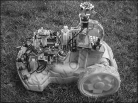
Fig.4 Experimental lawn robot
Firstly, an experiment was conducted to evaluate the accuracy of the ultrasonic distance measurement on which the performance of the scanning laser and ultrasonic absolute localization system is largely depended. The lawn robot is placed at four different distances away from the base station: 2 40 cm, 1 200 cm, 2 100 cm and 3 000 cm. When the distance is larger than 35 m, the ultrasonic wave becomes so weak that the receiver array on the robot fails to receive it. Fig.5 shows the accuracy. There are 40 measurements at each distance. The respective mean square errors of the four curves in Fig.5 are 2.9 cm, 3.0 cm, 5.4 cm and 8.3 cm. The absolute errors stay well within 10 cm when the distance is about 10 m and less. The error becomes larger when the robot gets further, but stays mostly within 10 cm when the distance is about 20 m. Even at the range of 30 m, the measurement error is acceptable at the 10 cm order of magnitude. The occasional wrong measurements with the absolute error lager than 15 cm can be filtered out by the data fusing strategy.
The next experiment aims at evaluating the accuracy of the scanning laser and ultrasonic absolute positioning system. The robot stops at several specified points in the environment and its position is calculated using the information coming from scanning laser and ultrasonic distance measurement. Fig.6 shows the results. The crossing point of the dashed line in each sub-figure is the robot’s specified position, and the red circles denote its calculated position of the absolute positioning system, namely (x , ya). The calculated position in each subfigure seems to be classified into two clusters. This is due to the angle error of the base station scanning laser. Our encoder linked with the scanning laser has a resolution of 1 000 pulses per circle. Therefore, one pulse error in the pulse counter will lead 0.36° error in angle measurement. Using encoders of higher resolution will have higher accuracy. The position error leaded by angle becomes larger when the robot gets farther from the base station. Within each point cluster, the error is caused by the fluctuation in ultrasonic distance measurement. As it can be seen from Fig.6, this scanning laser and ultrasonic positioning system is effective when the robot works within 30 m from the base station with the position error keeping at 10 cm order of magnitude.
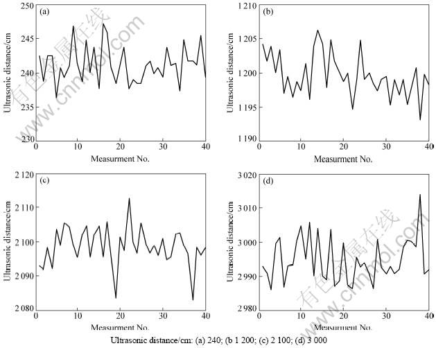
Fig.5 Accuracy of ultrasonic distance measurement
The last experiment evaluates the robot's real time running performance with the dead reckoning fused with the scanning laser and ultrasonic positioning system. Before the experiment, the parameters of noise models are calculated, where ![]() ,
, ![]() ,
, ![]() ,
, ![]() , Q(k)=Q(k-1)=diag{1 000, 1 000}, and R(k)= R(k-1)=diag{1 000, 1 000}. The initial conditions of Kalman filter are
, Q(k)=Q(k-1)=diag{1 000, 1 000}, and R(k)= R(k-1)=diag{1 000, 1 000}. The initial conditions of Kalman filter are ![]() (0|0)=(0, 1 200) and
(0|0)=(0, 1 200) and ![]() (0|0)= diag{1 000, 1 000} (angle unit: degree, distance unit: mm). The experiment was performed on an outdoor lawn. The robot was carefully driven along a 24 m×24 m square shape path marked on the lawn by white tape. (The white tape is only used to assist the driver in steering the robot exactly on the desired path, and not used for robot navigation.) In the progress, the robot's calculated position is stored in its memory when every 60 cm is traveled. Then the stored data is sent to computer through serial port. Fig.7 shows that the calculated position fits well with robot trajectory.
(0|0)= diag{1 000, 1 000} (angle unit: degree, distance unit: mm). The experiment was performed on an outdoor lawn. The robot was carefully driven along a 24 m×24 m square shape path marked on the lawn by white tape. (The white tape is only used to assist the driver in steering the robot exactly on the desired path, and not used for robot navigation.) In the progress, the robot's calculated position is stored in its memory when every 60 cm is traveled. Then the stored data is sent to computer through serial port. Fig.7 shows that the calculated position fits well with robot trajectory.
After that, let the robot navigate itself automatically along the 24 m×24 m square path, thus the blue dotted path shown in Fig.7, which was also pre-programmed in the robot. Since it’s hard to measure the robot’s position error during its navigation, its position is measured when it returns and stops at the starting point (0, 200 cm). This error measuring method was used in Refs.[2, 7]. But during our measurement, the robot’s software program remains running, and it keeps navigating after the measurement is done. This is in an effort to test the robot’s continuous localization ability for long time running. There are 20 continuous runs with each run consuming about 2.5 min. Both clockwise and anti-clockwise are tested. Let (xr, yr) denote the tape measured point where the robot returns and (xc, yc) denote its calculated position. The error points (xr-xc, yr-yc) between the returning points and the calculated position are denoted by small squares (clockwise measurements) and circles (anti-clockwise measurements) in Fig.8. Although the position error becomes reasonably larger when the robot gets further, the returning point error at (0, 200) keeps robustly within 10 cm order of magnitude. The accumulative error of relative dead reckoning is effectively compensated by fusing with the absolute positioning system. This confirms that the proposed method is convergent over long time running.
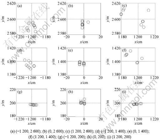
Fig.6 Accuracy of scanning laser and ultrasonic positioning system (Unit: cm)
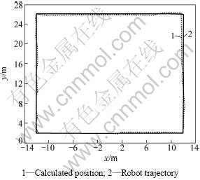
Fig.7 Robot trajectory and its calculated position
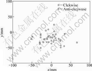
Fig.8 Robot trajectory and its calculated position
5 Conclusions
A low-cost, simple and convenient multi-sensor based mobile robot localization system is developed. The information from a low-cost gyro and two wheel encoders is fused to get the robot’s temporary heading and position. A scanning laser angle measurement and ultrasonic distance measurement system is employed to eliminate the accumulative error in robot’s dead reckoned heading and position. The proposed localization system can work both indoor and outdoor and needs no artificial landmarks and accurate map of the robot’s working environment, only a base station is needed. Experimental results show that the system works well on a lawn robot. With the localization system, the lawn robot can works on the lawn continuously for a long period of time within 30 m from the base station. And the lawn edge can be stored in the robot to avoid its surpassing the edge. Further more, the robot can initialize itself at any position within the system’s effective range.
Acknowledgment
Our work was supported by Yangtze Delta Region Institute of Tsinghua University, Zhejiang, China. The first author of this paper is sincerely appreciative of their kind cooperation.
References:
[1] Borenstein J, Everett H R, Feng L, et al. Mobile robot positioning- sensors and techniques[J]. Journal of Robotic Systems, 1997, 14(4): 231-249.
[2] Borenstein J, Feng L. Measurement and correction of systematic odometry errors in mobile robot[J]. IEEE Transactions on Robotics and Automation, 1996, 12(6): 869-880.
[3] Komoriya K, Oyama E. Position Estimation of a Mobile Robot Using Optical Fiber Gyroscope (OFG)[C]//Proceedings of International Conference on Intelligent Robot and System (IROS’94). Munich, Germany, 1994, 143-149.
[4] Hardt H J, Wolf D, Husson R. The Dead Reckoning Localization System of the Wheeled Mobile Robot ROMANE[C]//Proceedings of IEEE/SICE/RSJ International Conference on Multisensor Fusion and Integration for Intelligent Systems. Washington, DC, 1996: 603-610.
[5] Borenstein J, Feng L. Gyrodometry: A new method for combining data from gyros and odometry in mobile robots[C]//Proceedings of IEEE International Conference on Robotics and Automation. Minneapolis, 1996: 423-428.
[6] Borenstein J. Experimental evaluation of a fiber optics gyroscope for improving dead-reckoning accuracy in mobile robots[C]// Proceedings of IEEE International Conference on Robotics and Automation. Leuven, Belgium, 1998: 3456-3461.
[7] Chung H, Ojeda L, Borenstein J. Accurate mobile robot dead-reckoning with a precision-calibrated fiber optic gyroscope[J]. IEEE Transactions on Robotics and Automation, 2001, 17(1): 80-84.
[8] Cohen C, Koss F V. A Comprehensive study of three object triangulation[C]//Proceedings of SPIE Conference on Mobile Robots. Boston, MA, 1992: 95-106.
[9] Betke M, Gurvits L. Mobile robot localization using landmarks[J]. IEEE Transactions on Robotics and Automation, 1997, 13(2): 251-263.
[10] Font J M, Batlle J A. Dynamic triangulation for Mobile Robot localization using an angular state Kalman filter[C]//Proceedings of European Conference on Mobile Robots Ancona. 2005: 20-25.
[11] Tsai C C. A Localization system of a mobile robot by fusing dead-reckoning and ultrasonic measurements[J]. IEEE Transactions on Instrumentation and Measurement, 1998, 47(5): 1993-1998.
[12] Se S, Lowe D G, Little J J. Vision-based global localization and mapping for mobile robots[J]. IEEE Transactions on Robotics, 2005, 21(3): 364-375.
[13] Royer E, Lhuillier M, Dhome M, et al. Monocular vision for mobile robot localization and autonomous navigation[J]. Internal Journal of Computer Vision, 2007, 74(3): 237-260.
(Edited by ZHAO Jun)
Received date: 2011-04-15; Accepted date: 2011-06-15
Corresponding author: LIU Kai(1986-); Tel: +86-13811733220; E-mail: liukai08@mails.tsinghua.edu.cn

