�������滯ѧ��п������ HCl-H2SO4��ϵ�е�ʴ���ܵ�Ӱ��
��Դ�ڿ����й���ɫ����ѧ��(Ӣ�İ�)2013���12��
�������ߣ��೯�� ��ҵ�� �� �� �� �� ����ƽ
����ҳ�룺3650 - 3657
�ؼ��ʣ���������������ʴ��������港ʴ������������
Key words��Al foil; polarization; pitting corrosion; electrochemical etching; Al electrolytic capacitor
ժ Ҫ������ѹ�����������õ��������ں�Zn2+��5.0%NaOH��Һ��ʵʩ��ѧ��п������Ȼ����HCl+H2SO4���Һ�н���ֱ��������港ʴ�õ���ʴ�������ü��������о���ѧ��п���������港ʴʱ������ʴ��������ʴ��λ��Ӱ�죬���õ绯ѧ�����迹(EIS)�о���ѧ��п������������ⸯʴʱ�绯ѧ������Ӱ�죻ʹ��ɨ��羵(SEM)�۲컯ѧ��п�����Ը�ʴ������ͺ������ò��Ӱ�죻����100 V�γɵ�ѹ�¸�ʴ���ıȵ��ݡ�����������������滯ѧ��п�γɵ�Zn-Al��ż�����ڵ�ʴʱ���͵�ʴ�缫��Ӧ����������ߵ�ʴ�����ܶȣ�������������ʴ���ܶȺ�ʴ�ֲ��ľ����ԣ����ż�Һ��Zn2+Ũ�ȵ���ߣ���ʴ���ıȵ��������ӡ�
Abstract: The Al foil for high voltage Al electrolytic capacitor usage was immersed in 5.0% NaOH solution containing trace amount of Zn2+ and Zn was chemically plated on its surface through an immersion-reduction reaction. Such Zn-deposited Al foil was quickly transferred into HCl-H2SO4 solution for DC-etching. The effects of Zn impurity on the surface and cross-section etching morphologies and electrochemical behavior of Al foil were investigated by SEM, polarization curve (PC) and electrochemical impedance spectroscopy (EIS). The special capacitance of 100 V formation voltage of etched foil was measured. The results show that the chemical plating Zn on Al substrate in alkali solution can reduce the pitting corrosion resistance, enhance the pitting current density and improve the density and uniform distribution of pits and tunnels due to formation of the micro Zn-Al galvanic local cells. The special capacitance of etched foil grows with the increase of Zn2+ concentration.
Trans. Nonferrous Met. Soc. China 23(2013) 3650-3657
Chao-lei BAN1,2, Ye-dong HE2, Xin SHAO1, Juan DU1, Li-ping WANG1
1. College of Materials Science and Engineering, Institute of Non-ferrous Metals, Liaocheng University, Liaocheng 252059, China;
2. Beijing Key Laboratory for Corrosion, Erosion and Surface Technology, University of Science and Technology Beijing, Beijing 100083, China
Received 1 August 2012; accepted 15 October 2013
Abstract: The Al foil for high voltage Al electrolytic capacitor usage was immersed in 5.0% NaOH solution containing trace amount of Zn2+ and Zn was chemically plated on its surface through an immersion-reduction reaction. Such Zn-deposited Al foil was quickly transferred into HCl-H2SO4 solution for DC-etching. The effects of Zn impurity on the surface and cross-section etching morphologies and electrochemical behavior of Al foil were investigated by SEM, polarization curve (PC) and electrochemical impedance spectroscopy (EIS). The special capacitance of 100 V formation voltage of etched foil was measured. The results show that the chemical plating Zn on Al substrate in alkali solution can reduce the pitting corrosion resistance, enhance the pitting current density and improve the density and uniform distribution of pits and tunnels due to formation of the micro Zn-Al galvanic local cells. The special capacitance of etched foil grows with the increase of Zn2+ concentration.
Key words: Al foil; polarization; pitting corrosion; electrochemical etching; Al electrolytic capacitor
1 Introduction
Electrochemical etching and forming are key techniques in fabricating Al electrolytic capacitor foil electrode with high special capacitance. The electric capacitance (C) of Al electrolytic capacitors can be expressed by the formula of C=(��o��rS)/d, where ��o is the vacuum dielectric constant, ��r is the relative dielectric constant of the Al anodic oxide film, S is the specific internal surface area of Al foil electrode, and d is the film thickness. The enlargement of S is performed by electrochemical etching high-purity Al foils with
For high-voltage Al electrolytic capacitor anode foil, a densely uniform network of microscopic vertical etch tunnels is requisite for the maximum electrostatic capacitance and usually obtained by DC-etching, which usually consists of three continuous steps: pretreatment, etch tunnel formation, and widening of the etch tunnels [5]. Many variables are involved in the DC-etching process, including the grain size, cubicity and impurities [6,7] or pre-existing flaws of pure Al foil, pretreatments, acid composition, concentration and temperature, and current parameters [8-10]. The pretreatment is regarded as a critical step because it can improve the uniformity of the Al foil surface, which will induce an equal opportunity of pit nucleation and obtain an even distribution of high-density tunnel in the following tunnel formation stage. Various chemical or physical pretreatments have been studied and given tremendous attention. LEE et al [11] found that a two-step pretreatment with H3PO4 and H2SiF6 results in a high density of pre-etch pits on Al surface and generates a high density of etch pits. TATSURO et al [12,13] proposed a kind of thin polymer pattered mask on the Al foil, which can control the sites of development of the tunnel pits and enable the site-controlled tunnel pitting in Al foils [12,13]. However, it is difficult to spread the large area of such mask with the same periodic pattern and good adhesion on the Al foil in industry. LIN et al [14,15] found that the immersion of Al foil in Pb(NO3)2 and In(NO3)3 solution can give a higher density and a more uniform distribution of vertical tunnel etchings when subjected to DC-etching. This pretreatment along with other chemical ones in acid solutions has been widely adopted in Al etching industries but the pit density remains far below an ideal value, as predicted from the consideration of pit morphology. Furthermore, few works have focused on the influence of chemical plating Zn on DC-etching behavior of Al foil in HCl-H2SO4 solution and the etching characteristics according to the pretreatment have not been clarified sufficiently yet. Therefore, this work aims to discuss the effect of chemical plating Zn pretreatment on the surface and cross-section morphologies of etched Al foil by SEM. The corresponding electrochemical behavior of chemically galvanized Al foil is explored with PC and EIS. The results can help to elucidate the effects of chemical plating Zn pretreatment on pitting corrosion behavior of Al foil.
2 Experimental
2.1 Specimen
The specimen in this experiment was commercial aluminum foils for high-voltage electrolytic capacitors, with 99.99% purity, 95% (100) cubicity and 110 ��m in thickness.
2.2 Depth profile of Zn
Secondary ion mass spectrometry (SIMS, CMECA- IMS4F) was used to obtain the depth profiles of Zn in the foils. The ion source was O2+ and the working current was 400 nA. The spot size was about 10 ��m such that Zn content in the rolling line and between rolling lines can be examined.
2.3 Chemical plating Zn
Before etching, the specimens were immersed in 5.0%NaOH solution with trance amount of Zn2+ at 40 ��C for 1 min. The Zn2+ concentration varied at 100��10-6, 200��10-6, 300��10-6, 400��10-6 and 500��10-6. Some specimens were only rinsed with deionized water as comparative blank examples. All solutions used in this work were prepared from reagent grade chemicals and deionized water.
2.4 DC-etching and special capacitance measurement
After pretreatments, the specimen with the dimensions of 5.2 cm��13 cm was used as anode and mounted on a sample holder with the dimensions of 5 cm �� 9 cm exposed in 75 ��C 1 mol/L HCl + 5 mol/L H2SO4 etching solution. Two graphite electrode plates with dimensions of 15.5 cm �� 6.5 cm �� 8 cm were used as counter cathodes, with a gap of 25 mm between them. The specimen was placed parallel to the two electrode plates with a distance of 10 mm between each of them. Temperature of the solution was measured by alcohol thermometer and controlled by heating blender and temperature controller. Direct current etching was carried out immediately after placing the sample holder into the electrolyte. A constant current density of 150 mA/cm2 was applied for 100 s. The etched foil was anodized at 90 ��C in 150 g/L C6H16N2O4 for producing the anodic oxide film as dielectric layer by applying 100 V for 10 min and the special capacitance of the film was measured with a LCR meter in 150 g/L C6H16N2O4 at 30 ��C.
2.5 Etched morphology observation
After electrochemical etching, the samples were rinsed thoroughly with deionized water and dried in ambient condition. For surface morphology studies, the sample was examined under a scanning electron microscope (SEM, LEO 435VP). For sectional observation, which would shed light on tunnel development, the etched samples were anodized, mounted vertically in epoxy resin, mechanically polished, chemically dissolved in iodine methanol solution (10%I2/CH3OH), sputter-coated with gold and examined under SEM.
2.6 Polarization curves and AC impedance spectroscopy
After pretreatments, the samples, with a exposed geometrical surface area of 1 cm2 as working electrode, were immediately transferred to a cell containing 75 ��C 1 mol/L HCl+1 mol/L H2SO4, in which polarization curves and AC impedance spectroscopy were measured with a computer-controlled potentiostat/galvanostat (CHI 6301680). A Pt foil electrode and a SCE were used as counter electrode and reference electrode, respectively. During polarization measurement, the scanning rate was 10 mV/s. The range of frequency was from 1 Hz to 100 kHz in the EIS measurement.
3 Results and discussion
3.1 Surface morphology and composition of Zn2+- chemically plated foil
Figures 1(a) and (b) show the surface morphology and EDS spectrum of the 500��10-6 Zn2+-chemically plated foil, respectively, which indicate that numerous tiny particles of Zn are uniformly deposited on the
whole foil surface, especially concentrated along rolling lines. Second ion mass spectrometer (SIMS) was used to characterize the surface composition and depth profiles of Zn element in the raw Al foil, 200��10-6 and 500��10-6 Zn2+-chemically plated ones. Figure 1(c) shows the depth profiles of Zn located on rolling lines and between rolling lines. It can be found form Fig. 1(c) that for all locations, the concentration of Zn in the raw Al foil is much less than Zn-chemically plated ones. Figure 1(c) also shows that Zn is enriched in the surface layers (ca. 300-500  in depth) and approached null beneath the enriched layer. There is no difference in Zn concentration for the three foils in the inner section.
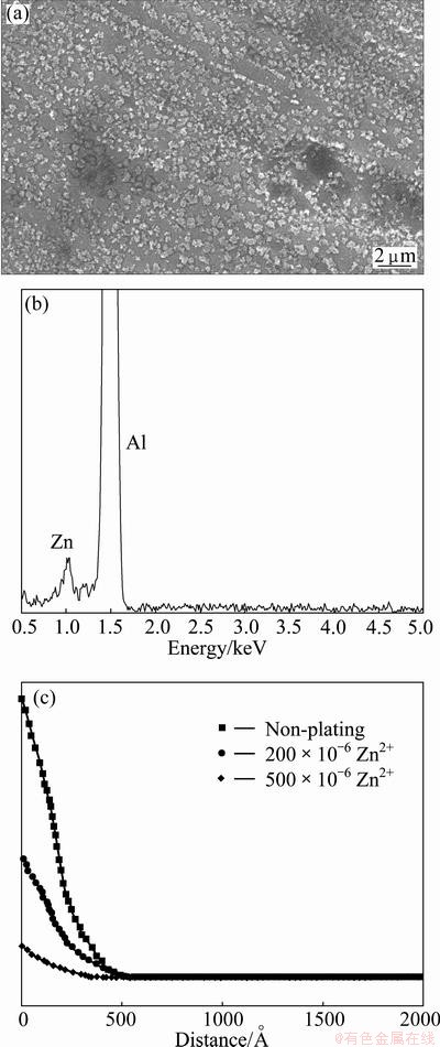
Fig. 1 Surface morphology (a), EDS spectrum (b) and SIMS results (c) of Zn2+-chemically plated foil
3.2 Surface morphologies of etched foil
The etched surface morphology for blank sample is shown in Fig. 2(a). After chemical plating Zn in different Zn2+ concentrations solutions, the corresponding surface morphologies of etched Al foil are give in Figs. 2(b)-(f), respectively. It can be found in Fig. 2(a) that the rolling line effect, which results in concentrated etching along rolling lines, leaving vast areas between the unattached, is evident for blank sample. In contrast, after chemical plating Zn, etchings are uniformly distributed both on rolling lines and between rolling lines in Figs. 2(b)-(f). Moreover, with increasing Zn2+ concentration, the rolling line effect gradually disappears and the etching is more and more evenly distributed on the entire Al foil from Figs. 2(b)-(f).
During high-temperature annealing treatments and rolling processes for cubic texture formation of Al foil, a distorted oxide film due to roll crushing and a rolling oil contamination layer are both present on the Al foil, which makes the Al foil surface heterogeneous in composition and microstructure. Meanwhile, rolling line is a high strain area. Much researches have indicated that there is a high concentration of impurities, vacancies and dislocations located in rolling lines, which serve as the major sites for pit initiation [14,15]. For blank sample, the pitting obviously prefers to occur along rolling lines compared with between rolling lines, as illustrated in Fig. 2(a).
When immersing Al foil in alkali solution containing Zn2+, the distorted oxide film and the remnant rolling oil gradually dissolved, which helps to homogenize the Al foil surface and promote pitting initiation evenly on the whole Al foil, no matter along rolling lines or between neighboring lines. Furthermore, an immersion-reduction reaction simultaneously occurs, i.e. 2Al+3Zn2+�� 2Al3++3Zn. The potential of zinc is much higher than that of aluminum. In the following electrochemical etching process, zinc acts as a cathode and aluminum as an anode. Zinc and aluminum, maybe especially along rolling lines, form local galvanic cells, which can facilitate pitting and more pits can be found, as shown in Figs. 2(b)-(f). Meanwhile, with increasing Zn2+ concentration, more Zn-Al micro local galvanic cells are formed, the rolling line effects gradually disappeared and etchings distribute uniformly over the foil surface.
3.3 Cross-section morphologies of etched foil
The cross-section micrograph of etched blank sample is shown in Fig. 3(a). After chemical plating Zn in alkali solution containing different Zn2+ concentrations, the corresponding cross-section morphologies of etched Al foil are give in Figs. 3(b)-(f), respectively. The shape and array of etch tunnels developed along <100> directions are observed. However, the tunnels are generally sparse in distribution and coarse in size for blank sample. After chemical plating Zn, tunnels become dense and fine in size. These phenomena are consistent with Fig. 2.
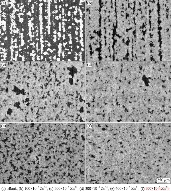
Fig. 2 Effect of chemical plating on surface of etched Al foils in alkali solution with different Zn2+ concentrations
For blank sample, the surface oxide film is thick and it is difficult for Cl- to diffuse and electro-migrate in such thick film. Pitting preferably happens in the weak points of the film, such as impurities, dislocations and vacancies, where Cl- is preferably adsorbed and diffused. These points concentrate along rolling lines, where tunnels are dense but the tunnels are sparse between rolling lines.
After chemical plating Zn in alkali solution, the film partly dissolves and becomes thin. More Cl- can easily diffuse and migrate to induce pitting. Moreover, the Zn-Al micro galvanic cells can accelerate pitting. With increasing Zn2+ concentration, more Zn-Al galvanic cells are produced on the Al foil, which can help to increase the pits and tunnel density and improve their distribution. At the same time, the tunnels become fine in size because the high density of them has to supply the same amount of applied current.
3.4 Polarization curves
Figure 4 shows the polarization curves in 75 ��C 1 mol/L HCl+5 mol/L H2SO4 for blank sample and trace Zn pre-deposited specimen. It can be found that the pitting potential and free corrosion potential for blank sample are the most notable and its pitting current is the most negative. With introduction of trace Zn on the Al foil and increasing Zn2+ in alkali solution, the pitting potential and free corrosion potential gradually shift toward to a more negative value and the corresponding pitting current gradually increases. These phenomena suggest that the Al foil surface becomes more valuable following chemically plating Zn pretreatment in alkali solution, due to dissolution of the protective oxide film and formation of more Zn-Al micro galvanic local cells. Here, the Zn-Al micro galvanic cells can reduce the pitting corrosion resistance and serve as primary sits for pitting, apart from weak point along the rolling lines, which is in consistent with Figs. (2) and (3).
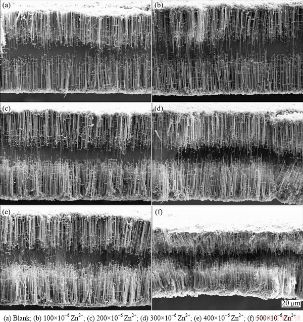
Fig. 3 Effect of chemical plating Zn on cross-section of etched Al foils in alkali solution containing different Zn2+ concentrations

Fig. 4 Effect of chemical plating Zn in alkali solution containing different Zn2+ concentrations on polarization curves of Al foil in 75 ��C 1 mol/L HCl+5 mol/L H2SO4
Generally, pit initiation of aluminum in chloride solutions takes into account adsorption of chloride ions on the oxide surface, penetration of chloride ions through the oxide film and chloride-assisted localized dissolution at the oxide-metal interface. During immersion of Al foil in alkaline solution containing trace amount of Zn2+, the next reactions occur on the Al foil surface.
Al2O3+2OH-�� +H2O (1)
2Al+2OH-+2H2O��+3H2�� (2)
2Al+3Zn2+��2 Al3++3Zn�� (3)
The apparent of hydrogen bubbles can be observed in the alkaline solution. At the same time, the barrier oxide film of Al2O3 becomes thin, which will reduce the resistance of penetration of chloride ions, promote chloride-assisted localized dissolution at the oxide-metal interface and increase pitting density in the following DC-etching stage. More importantly, the deposited Zn, as the second phase, spreads uniformly on the Al foil surface and may constitute galvanic cell with Al. On the initiation of DC-etching, the following usual electrode reactions occur:
Al��Al3++3e (Al foil anode) (4)
2H+ +2e �� H2 (Graphite cathode electrode) (5)
Zn��Zn2++2e (Al foil anode) (6)
According to the Nernst equation: E=E0+ the equilibrium electrode potential values of electrode reactions (4) and (6) can be reckoned as about -1.8 V (vs SHE) and -0.97 V (vs SHE), supposing that the concentrations of Al3+ and Zn2+ are 10-6 mol/L. Therefore, Zn is cathode and Al is anode in the micro Zn-Al galvanic cells. On the initiation of DC-etching, the pitting current is made of two parts: one part from the applied anodic current and the rest from the galvanic current between Al anode and Zn cathode. With increase in Zn2 concentration of chemical plating solution, more micro Zn-Al galvanic cells are formed on Al foil, leading to enhancement of galvanic current and pitting current, as shown in Fig. 4.
3.5 AC impedance characterization
Figure 5(a) shows the effect of chemically plating Zn on electrochemical impedance spectra of Al foil, in which the measured impedance spectra are plotted into Nyquist diagram. It is clearly seen that the Nyquist diagram is mainly composed of a capacitive arc at high frequency and an inductive loop at low frequency. CAO et al [16] thought that the inductive arc is linked to the passive film on the surface, and the appearance of inductive component is the important feature of EIS during pit incubation. They analyzed the growth and decline of passive film during pit incubation and put forward a mathematical model and the corresponding equivalent circuit. The Nyquist diagram of the equivalent circuit is composed of a capacitive arc at high-mediate frequency and an inductive loop at low frequency. KEDDAM et al [17] thought that the inductive loop observed is associated with the weakening of the protective effectiveness of the aluminum oxide layer due to the anodic dissolution of aluminum alloy. PENG et al [18] also observed an inductive loop in the early stage of pitting corrosion, and they put forward an equivalent circuit which contained negative resistance and negative capacitance to explain this phenomenon. But the physical meaning of negative resistance and negative capacitance is not definite.
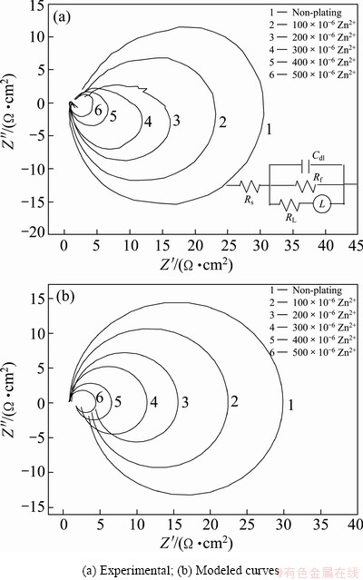
Fig. 5 Effect of chemical plating Zn in different Zn2+ concentrations solution on EIS of Al foil in 75 ��C 1 mol/L HCl+5 mol/L H2SO4
In our study, the diameters of both capacitive arc and inductive loop for blank sample are much larger than those for trace Zn chemically plated specimen. Moreover, with increasing Zn2+ concentration in alkali solution, the sizes of capacitive arc and inductive loop become small. The high-frequency impedance arc is generally attributed to the processes occurring at the electrode-electrolyte interface. The diameter of this arc can be regarded as the ion transfer resistance and the capacitance of electric double layer at the electrode-electrolyte interface. The smaller the arc diameter is, the smaller the ion transfer resistance and the larger the capacitance. With increasing Zn2+ concentration in alkali solution, more Zn-Al micro galvanic local cells form on the Al foil and promote pitting corrosion, leading to a smaller capacitive arc in EIS, a higher pitting density in the polarization curves and a higher density of pits and tunnels, as illustrated in Figs. 4,3,2, respectively.
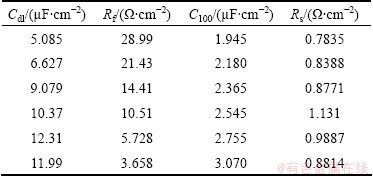
The electrochemical impedance spectra can be further analyzed by fitting the equivalent circuit model in the inserted figure of Fig. 5(a), where Cdl is double layer capacitance and proportional to the specific surface area of the etched area, Rf is charge transfer resistance, Rs is the solution resistance, RL and L are equivalent resistance and inductance, respectively. The good correspondence between the experimental curves and the modeled curves is obtained using this equivalent, as shown in Fig. 5(b). Table 1 lists the parameters from the equivalent circuit model, in which the Cdl, Rf, Rs and special capacitance (C100) of 100 V formation voltage anodic oxide film are also listed. The physical meanings of RL and L are vague, and their values are not given here. As shown in Table 1, with chemical plating Zn and increasing Zn2+ in alkali solution, the Cdl and C100 gradually increase and Rf gradually decreases. This regularity is caused by the formation of more Zn-Al micro galvanic local cells, serving as primary sits for pitting.
Table 1 Circuit parameters from EIS data and special capacitance (C100) of 100 V formation voltage
4 Conclusions
1) Before electro-etching, chemical plating Zn in alkali solution containing trace Zn2+ can form micro Al-Zn galvanic local cells, dissolve oxide film on Al foils surface, make Al foil more vulnerable to Cl- and reduce the charge transfer resistance so as to increase pitting density, improve the density and distribution of pits and tunnels, leading to the enlargement of special area and capacitance of etched foil.
2) To some extent, with increasing Zn2+ concentration in alkali solution, the rolling line effect can be further reduced or overcome due to formation of more dense and uniformly distributed micro Al-Zn galvanic local cells, resulting in a more increase of tunnel density, special area and capacitance of etched foil.
References
[1] BU Jun-fu, SUN Lan, WU Qi, WANG Meng-ye, LIN Chang-jian. Al2O3-TiO2 composite oxide films on etched aluminum foil fabricated by electrodeposition and anodization [J]. Science China Chemistry, 2011, 54(10): 1558-1564.
[2] DU Xian-feng, XU You-long. Formation of Al2O3-BaTiO3 nanocomposite oxide films on etched aluminum foil by sol-gel coating and anodizing [J]. Journal of Sol-Gel Science and Technology, 2008, 45: 57-61.
[3] PARK S S, LEE B T. Anodizing properties of high dielectric oxide films coated on aluminum by sol-gel method [J]. Journal of Electroceramics, 2004(13): 111-116.
[4] FENG Zhe-sheng, CHEN Jin-ju, ZHANG Rui, ZHAO Ning. Formation of Al2O3-Nb2O5 composite oxide films on low-voltage etched aluminum foil by complexation-precipitation and anodizing [J]. Ceramics International, 2012(38): 3057-3061.
[5] OH H J, LEE J H, AHN H J, JEONG Y, PARK N J, KIM S S, CHI C S. Etching characteristics of high-purity aluminum in hydrochloric acid solutions [J]. Materials Science and Engineering A, 2007, 449-451: 348-351.
[6] SONG Jing-bo, MAO Wei-min, YANG Hong, FENG Hui-ping. Effect of trace Sn on corrosion behaviors of high voltage anode aluminum foil [J]. Transactions Nonferrous Metals Society of China, 2008, 18(4): 879-883.
[7] MAO Wei-min, YANG Hong, YU Yong-ning, FENG Hui-ping, XU Jin. Influence of trace Mg on corrosion structure of high voltage aluminum foil [J]. The Chinese Journal of Nonferrous Metals, 2003, 13(5): 1057-1059. (in Chinese)
[8] CHIU Y H, OU B L, LEE Y L. Effect of acid concentration and current density on DC etching of aluminum electrolytic capacitor foil [J]. Korean Journal of Chemical Engineering, 2007, 24(5): 881-887.
[9] BAN Chao-lei, HE Ye-dong. Behavior of increasing diameter of tunnels on high voltage Al foil by anodic electrolysis [J]. The Chinese Journal of Nonferrous Metals, 2008, 18(12): 2190-2195. (in Chinese)
[10] BAN Chao-lei, HE Ye-dong. Mechanism on controlling limiting length of tunnels on Al foil electroetched in HCl-H2SO4 [J]. Transactions of Nonferrous Metals Society of China, 2009, 19(3): 601-605.
[11] LEE J K, KIM J Y, KIM J T, LEE J H, CHUNG H Y, TAK Y S. Effects of pretreatment on the aluminum etch pit formation [J]. Corrosion Science, 2009, 51: 1501-1505.
[12] TATSURO F, KAZUYUKI N, HIDEKI M. Optimization of etching conditions for site-controlled tunnel pits with high aspect ratios in Al foil [J]. Journal of the Electrochemical Society, 2010, 157(4): C137�CC139.
[13] KAZUYUKI N, TATSURO F, AKIFUMI T, HIDEKI M. Fabrication of site-controlled tunnel pits with high aspect ratios by electrochemical etching of al using masking film [J]. Electrochemical and Solid-State Letters, 2007, 10(10): C60-C62.
[14] LIN W, TU G C, LIN C F, PENG Y M. The effects of indium impurity on the DC-etching behaviour of aluminum foil for electrolytic capacitor usage [J]. Corrosion Science, 1997, 39(9): 1531-1543.
[15] LIN W, TU G C, LIN C F, PENG Y M. The effects of lead impurity on the DC-etching behaviour of aluminum foil for electrolytic capacitor usage [J]. Corrosion Science, 1996, 38(6): 889-907.
[16] CAO Chu-nan, WANG Jia, LIN Hai-chao. Effect of Cl- ion on the impedance of passive film covered electrodes [J]. Journal of Chinese Society of Corrosion and Protection, 1989, 9(4): 261-270.( in Chinese)
[17] KEDDAM M, KUNTZ C, TAKENOUTI H , SCHUSTER D, ZUILI D. Exfoliation corrosion of aluminum alloys examined by electrode impedance [J]. Electrochimica Acta, 1997, 42(1): 87-97.
[18] PENG Yong-yi, YIN Zhi-min, LI San-hua. Evaluation of pitting corrosion of Al-Mg-Mn-Sc-Zr alloy in EXCO solution by EIS [J]. Transactions of Nonferrous Metals Society of China, 2005, 15(6): 1226-1230.
�೯��1, 2����ҵ��2���� ��1���� ��1������ƽ1
1. �ijǴ�ѧ ���Ͽ�ѧ�빤��ѧԺ����ɫ�����о�Ժ���ij� 252059��
2.�����Ƽ���ѧ �����и�ʴ��ĥʴ����漼���ص�ʵ���ң����� 100083
ժ Ҫ������ѹ�����������õ��������ں�Zn2+��5.0%NaOH��Һ��ʵʩ��ѧ��п������Ȼ����HCl+H2SO4���Һ�н���ֱ��������港ʴ�õ���ʴ�������ü��������о���ѧ��п���������港ʴʱ������ʴ��������ʴ��λ��Ӱ�죬���õ绯ѧ�����迹(EIS)�о���ѧ��п������������ⸯʴʱ�绯ѧ������Ӱ�죻ʹ��ɨ��羵(SEM)�۲컯ѧ��п�����Ը�ʴ������ͺ������ò��Ӱ�죻����100 V�γɵ�ѹ�¸�ʴ���ıȵ��ݡ�����������������滯ѧ��п�γɵ�Zn-Al��ż�����ڵ�ʴʱ���͵�ʴ�缫��Ӧ����������ߵ�ʴ�����ܶȣ�������������ʴ���ܶȺ�ʴ�ֲ��ľ����ԣ����ż�Һ��Zn2+Ũ�ȵ���ߣ���ʴ���ıȵ��������ӡ�
�ؼ��ʣ���������������ʴ��������港ʴ������������
(Edited by Xiang-qun LI)
Foundation item: Project (51172102) supported by the National Natural Science Foundation of China; Project (BS2011CL011) supported by Promotive Research Fund for Young and Middle-aged Scientists of Shandong Province (doctor fund), China
Corresponding author: Chao-lei BAN; Tel: +86-635-8230831; E-mail: banchaolei@lcu.edu.cn
DOI: 10.1016/S1003-6326(13)62913-1

