J. Cent. South Univ. (2017) 24: 683-691
DOI: 10.1007/s11771-017-3469-x

A simplified model to predict blast response of CFST columns
ZHANG Jun-hao(�¾���)1, CHEN Bin(�±�)2, JIANG Shi-yong(������)1
1. Department of Civil Engineering, Logistical Engineering University, Chongqing 401311, China;
2. Institute of Engineering Mechanics, China Earthquake Administration, Harbin 150080, China
 Central South University Press and Springer-Verlag Berlin Heidelberg 2017
Abstract: In order to study the dynamic response of concrete-filled steel tube (CFST) columns against blast loads, a simplified model is established utilizing the equivalent single-degree-of-freedom (SDOF) method, which considers the non-uniform distribution of blast loads on real column and the axial load-bending moment (P-M) interaction of CFST columns. Results of the SDOF analysis compare well with the experimental data reported in open literature and the values from finite element modeling (FEM) using the program LS-DYNA. Further comparisons between the results of SDOF and FEM analysis show that the proposed model is effective to predict the dynamic response of CFST columns with different blast conditions and column details. Also, it is found that the maximum responses of the columns are overestimated when ignoring the non-uniformity of blast loads, and that neglecting the effect of P-M interaction underestimates the maximum response of the columns with large axial load ratio against close range blast. The proposed SDOF model can be used in the design of the blast-loaded CFST columns.
Key words: concrete-filled steel tube (CFST) columns; dynamic response; single-degree-of-freedom (SDOF) analysis; non-uniform blast loads; axial load-bending moment (P-M) interaction
1 Introduction
Concrete-filled steel tube (CFST) columns have been widely used in engineering structures such as high-rise buildings, arch bridges and subway stations, as they have advantages of high strength and excellent ductility due to a confinement effect and a changed buckling mode [1-3]. With the increase of terrorist bombings in recent years, blast resistance of the structures has become a consideration in their design process [4]. When subjected to blast loads, columns may suffer a loss of bearing capacity to a certain extent due to the damage imparted, which may induce the collapse of the columns and even cause the progressive collapse of the whole structure. In addition, both concrete and steel, of which CFST columns are composed, may respond to blast loads at very high strain rates [5], thus making the dynamic analysis of CFST columns different from that under static loads and earthquake actions. Therefore, it is of realistic significance to study the dynamic behaviors of CFST columns under blast loading.
Recently, many researchers have conducted blast tests, numerical modeling and theoretical analysis to investigate the blast-induced responses of CFST columns. LI et al [5] experimentally studied the dynamic behaviors of CFST columns through a series of field blast experiments. They analyzed the effects of explosive mass, standoff distance, axial load ratio, concrete strength grade and steel ratio on the deflection and strain responses of CFST columns. ZHANG et al [6] carried out blast tests on the axially compressed CFST column members. Results indicated that CFST columns showed good flexural resistance against blast loads. NGO et al [7] utilized the coupled Arbitrary Lagrange Euler (ALE) blast wave-structure interaction algorithms and numerically investigated the failure patterns, deformation histories, and energy absorption characteristics of CFST members subjected to near-field blast loading. Compared with the blast tests and numerical modeling which are very expensive and complicated, the dynamic analysis utilizing the equivalent single-degree-of-freedom (SDOF) method has the merits of simplicity with a high level of accuracy, for which it is widely accepted in the engineering practice [8, 9].
The equivalent SDOF model was firstly put forward by NORRIS et al [10] and BIGGS and TESTA [11]. The basic physical quantities of this model are equivalent loads, equivalent resistance and equivalent mass. In order to analyze the blast-loaded CFST columns using the equivalent SDOF method, several key factors should be taken into account; they are the blast loads acting on the column, strain rate effect of materials, interaction between the steel tube and concrete infill and axial load-bending moment (P-M) interaction. The traditional SDOF method is based on the assumption of uniform blast loads [12], which is valid for far-field blast loading and nuclear explosion. However, when the charge is near the structure, the generated blast loads are usually non-uniform over the surface of the components [13, 14]. FUJIKURA et al [13] used the equivalent uniform impulse incorporated into the SDOF method to calculate the maximum deformation of CFST columns having elastic-perfectly plastic behaviors by assuming that all the energy imparted to the equivalent systems by the blast loading is converted into their internal strain energy. Such method is meaningful provided that the blast loading belongs to the impulsive load regime, i.e. the load duration is quite shorter than the natural vibration period of the column, rather than the dynamic or quasi-static loads regimes. REMENNIKOV and UY [14] also proposed a SDOF model for the near-field blast impulse to predict the response of CFST members, and good agreement was observed between the experiment results and that from the SDOF analysis. However, it is noted the effects of axial loads and P-M interaction on CFST columns are neglected in this method, which is not suitable for CFST members subjected to combined axial and lateral loads.
Therefore, this work focuses on the dynamic responses of blast-loaded CFST columns by using the SDOF model, in which the dynamic equilibrium equation of the equivalent system is established considering the non-uniformity of the blast loads and the effect of P-M interaction. Comparisons of the SDOF analysis results with experimental data and the FEM values show that the proposed SDOF model has a high level of accuracy and computational efficiency.
2 SDOF model for CFST column analysis
As illustrated in Fig. 1, the real column can be replaced by an equivalent SDOF mass-spring system, in which the load, resistance and mass of the real system with an assumed deformed shape are converted into the corresponding equivalent quantities to maintain conservation of energy between the two systems. The responses of the equivalent system are determined by solving the dynamic equilibrium equation as follows:
 (1)
(1)
where  and y are acceleration and displacement of the mass, respectively, which are equal to the acceleration and displacement at the mid-span of the column; m is the column mass; F(t) is the total blast load applied on the column at time t; R(y) is the resistance of the column; KM, KR and KL are the mass factor, resistance factor and load factor, respectively. Since the resistance factor KR is equal to the load factor KL [15], dividing both sides of Eq. (1) by KL yields
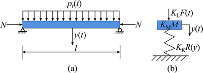
Fig. 1 Real column (a) and equivalent SDOF system (b) under blast loading
 (2)
(2)
where me=KLMM is the mass of equivalent system; KLM is the load-mass factor, KLM=KM/KL.
2.1 Determination of blast loads F(t)
In this work, the time history of blast loads has a linearly decaying pressure profile as follows:
 (3)
(3)
where Fm is the peak of the total blast loads acting on the column, and td is the duration of blast loads.
For the SDOF analysis of CFST columns, the real blast loads acting on the column surface are converted into equivalent uniform loads based on the virtual work done by the two loads maintaining a constant [16, 17], so that the energy absorbed by the system maintains the same for both the real and the equivalent loads.
As the width of the column is much smaller than the height of it, only the variation of blast loads along the height of column is considered. According to the instantaneous explosion theory [18], the distribution of blast pressure produced by the spherical charge is obtained as
 (4)
(4)
where �� is the angle of incidence of the blast wave; p�� is the peak of the reflected pressure related to angle ��; p0 is the peak of the reflected pressure at the point directly facing the charge.
As indicated by the test results from LI et al [5] and ZHANG et al [6], CFST columns favor a flexural-mode controlled response. In the present study, the shear damage mode of the component, which should be prevented through proper design in the engineering practice, is not considered, and the mode of CFST columns response is assumed to be flexural, as shown in Fig. 2. Therefore, the virtual work done by the non- uniform loads on an elementary column segment dx is given by
 (5a)
(5a)
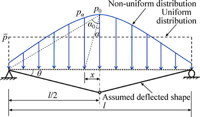
Fig. 2 Converting non-uniform blast loads into equivalent uniform loads
where w is the width of the column; �� is the rotation of the support; l is the span of the column; x is the distance from the point of interest to the mid-span of the column.
If the standoff distance of charge is denoted as Z, then x=Ztan�� and dx=Z/cos2��d��. Thus, Eq. (5a) becomes
 (5b)
(5b)
Inserting Eq. (4) into Eq. (5b) yields
 (5c)
(5c)
Considering the symmetry of the blast loads acting on the column, integration of Eq. (5c) in the interval of [0, ��0] arrives at

 (6)
(6)
where W1 is total virtual work done by the non-uniform loads.
Similarly, the virtual work done by the equivalent uniform loads on the segment dx is given by
 (7)
(7)
Integration of Eq. (7) yields
 (8)
(8)
where W2 is the total virtual work done by the equivalent loads.
Equating Eq. (6) with Eq. (8) yields
 (9)
(9)
which is the formula for converting the non-uniform blast pressure into equivalent uniform pressure. When the column is subjected to mid- to far-field blast loading, i.e. ��0��0,  is approximately equal to p0.
Using Eq. (9), Fm in Eq. (3) can be expressed as
 (10)
(10)
The methods presented by KINGERY and BULMASH [19] are utilized in the study to calculate p0 and td. Based on a large number of experimental data, KINGERY and BULMASH developed diagrams and equations for computing air blast parameters, which are widely accepted by most researchers and are also incorporated into the software LS-DYNA for modeling blast loads [20]. And the load duration td is obtained as
 (11)
(11)
where i0 is the specific impulse acting on the segment of column surface directly facing the charge.
2.2 Derivation of resistance function R(y)
Figure 3 illustrates the resistance R(y) of the CFST column, assumed to be simply supported in the study. To obtain R(y), several parameters are needed; they are the ultimate resistance, Ru, residual resistance, Rr, elastic stiffness, KE, plastic stiffness, KP, yield displacement, yE, and ultimate displacement, yu. Note that in the work the resistance function has a negative plastic stiffness, which is observed from the test results [6, 21, 22].
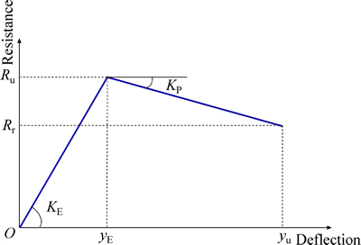
Fig. 3 Sketch of resistance function of CFST columns
The ultimate flexural resistance for the column under uniform loads is
 (12)
(12)
where Myu is the ultimate bending strength of the column under combined axial and lateral loading.
According to HAN and YANG [21], for the axially compressed CFST column with rectangular cross section, Myu can be obtained using the following relations which account for the P-M interaction,
 (13)
(13)
where �� is the stability reduction factor; Nu is the axial bearing capacity; N and M are the axial loads and bending moment applied on the column, respectively; a, b, c and d are design parameters; 1/d is the moment magnification factor (MMF) accounting for the effect of secondary moment, d=1-0.25N/NE; NE is the Euler��s critical load; Mu is the ultimate bending strength of the column under pure bending and is given by
 (14)
(14)
where ��m is the flexural strength index, ��m=1.04+ 0.48ln(��+0.1); Wscm is the section modulus of the member, Wscm=wh2/6, h is the column depth; fscy is the yield strength of the composite section, fscy=(1.18+ 0.85��)fck; �� is the confinement factor defined as [21]
 (15)
(15)
where As and Ac are the cross sectional areas of steel tube and infill concrete, respectively; fy is the yield stress of the steel tube; fck is the characteristic concrete strength.
The elastic stiffness of CFST members is obtained as
 (16)
(16)
where the effective flexural stiffness of the composite member EI is expressed as [14, 21]
 (17)
(17)
where Es is the elastic modulus for the structural steel, which is 206 GPa; Ec is the elastic modulus for the structural concrete, Ec=105/(2.2+34.7/fcu); fcu is concrete cube strength; Is and Ic are the second moment of area for the steel section and the concrete (assumed to be uncracked), respectively. The coefficient of 0.6 is accounting for the effect of concrete cracking on the effective flexural stiffness.
The yield displacement at the mid-height of the columns is given by
 (18)
(18)
Through experiments, many researchers have revealed that the resistance-displacement relations of most CFST columns have a descending stage. Thus, the plastic stiffness of the column is calculated as
 (19a)
(19a)
Further, taking into consideration that Rr=0.85Ru [21] and KE=Ru/yE, Eq. (19a) is transformed as
 (19b)
(19b)
where �� is the ductility coefficient, ��=yu/yE.
The ultimate displacement can be obtained as
 (20)
(20)
Due to the strain rate effect, the strength of steel and concrete could be higher than that under static loads. And the enhancement of material strength is considered in the SDOF analysis by using the dynamic increase factor (DIF). For far-field (Z>15r0) and near-field blast loading (Z<15r0), the strain rates are at least 0.1 s-1 and 0.3 s-1, respectively [8], where r0 denotes the radius of the charge. Based on K&C model [23], the DIF of the yield stress of steel (SDIF) is
 (21)
(21)
where  is the strain rate of the steel tube; ��1=0.074- 0.04fy/414. Equation (21) is valid when 10-4 s-1
 255 s-1 and 270 MPa��fy��710 MPa.
The DIF of the concrete compressive strength (CDIF) is also given by K&C model as
 (22)
(22)
where  is the strain rate of the concrete infill;
  =30��10-6 s-1 is the reference strain rate; ��2 and �� are parameters related to fcu, ��2=(5+3fcu/4)-1, lg ��=6.156��2- 0.49.
2.3 Derivation of equivalent mass me
As stated previously, the equivalent mass me=KLMm, where KLM= KM/KL. The mass factor KM and the load factor KL can be determined as [9]
 (23a)
(23a)
 (23b)
(23b)
where m(x) is the mass per unit length of blast-loaded component;  is the deflected shape function of the component; p(x) is the load shape function of the component.
If the distribution of the column mass and blast loads is uniform along the span of the column, i.e. m(x)=m/l and p(x)=, then
 (24a)
(24a)
 (24b)
(24b)
 (24c)
(24c)
Equation (24c) indicates that the load-mass factor KLM is only related to  providing that the distribution of mass and blast loads is uniform along the column span. According to PDC TR-06-01 [9], for a simply supported member under uniform loads, the value of KLM is 0.78 when the member responds to blast loading in the elastic range and is 0.66 for the plastic response. For the elastic-plastic analysis of CFST columns in this work, an average KLM=(0.78+0.66)/2= 0.72 is used.
2.4 SDOF analyses
For the solution of Eq. (2), varied possibilities regarding the relative magnitude of tE and td should be considered. In this regard two cases are assumed: 1) tEd and 2) tE>td, where tE is the moment when the elastic phase of the column terminates.
Case 1: tEd. It corresponds with dynamic or quasi-static regime of loading when plastic stage of the column starts within the duration of blast loads, and the dynamic response is obtained in three phases.
�� 0 tE: In this phase the response is elastic and the dynamic equilibrium equation of the system is
 (25)
(25)
For the initially static structure, using Duhamel integration method, Eq.(25) can be solved as
 (26a)
(26a)
 (26b)
(26b)
where 
The initial conditions for the second phase are given by Eqs. (26a)-(26b) as
 (27a)
(27a)
 (27b)
(27b)
�� tEtd: In this phase the response of the system is plastic and the motion equation is
 (28)
(28)
The solution of the above equation with initial conditions is

 (29a)
(29a)

 (29b)
(29b)
where
 (30a)
(30a)
 (30b)
(30b)
 (30c)
(30c)
 (30d)
(30d)
 (30e)
(30e)
This phase terminates at time t1=td-tE. Thus, the initial displacement and velocity for the third phase are given by Eqs. (29a)-(29b) as
 (31a)
(31a)
 (31b)
(31b)
�� t��td: In this phase, the response is dominated by the following differential equation:
 (32)
(32)
The solution of Eq. (32) is derived as

 (33a)
(33a)

 (33b)
(33b)
where
 (34a)
(34a)
 (34b)
(34b)
 (34c)
(34c)
Case 2: tE>td. It means that the column is elastic during blast loading, which corresponds with the impulsive loading regime. The blast response under such circumstance is derived in three phases.
�� 0��td: In this phase, the response is dominated by Eq. (25) with the solutions of Eqs. (26a)-(26b). The initial conditions for the second phase are obtained using Eqs. (26a)-(26b) as
 (35a)
(35a)
 (35b)
(35b)
�� td��tE: The motion equation in this phase is
 (36)
(36)
And the solution of Eq. (36) is obtained as
 (37a)
(37a)
 (37b)
(37b)
The initial displacement and velocity of the next phase are given by Eqs. (37a)-(37b) as
 (38a)
(38a)
 (38b)
(38b)
�� t��tE: In this phase, the equation of motion is as Eq. (32) and the solution with initial conditions is

 (39a)
(39a)

 (39b)
(39b)
where
 (40a)
(40a)
 (40b)
(40b)
3 Finite element modeling (FEM)
The finite element program LS-DYNA was used in this work to simulate the blast responses of CFST columns and to compare its results with those of the SDOF analysis. Figure 4 exhibits a finite element model of a CFST column. In conformity with the test column described in the following section, the specimen was simply supported by four rollers (two at each ends). A steel plate was included between the roller and the specimen to avoid stress concentration. Also, a rigid plate was added in the numerical model for applying axial load.
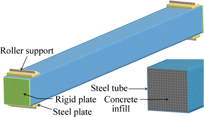
Fig. 4 Finite element model of CFST column
The model MAT_PLASTIC_KINEMATIC was adopted for steel simulation, in which the required input material parameters including the steel yield stress, density, fracture strain, and Poisson ratio were taken as 485 MPa, 7850 kg/m3, 0.20 and 0.30, respectively. The strain rate parameters in the model were obtained from open literature for the same grade of steel [24], i.e. C=40 and q=5. The concrete was modeled with MAT_CONCRETE_DAMAGE_REL3. Based on the compressive strength and density of concrete, which were 37.9 MPa and 2440 kg/cm3 in this study, the program automatically generated other relevant concrete parameters. The reliability of this concrete model in predicting the responses of concrete structures to blast loads has been demonstrated in Refs. [7, 23].
The 8-node solid elements with single point integration algorithm were used in the study to simulate the steel tube and the infill concrete. A perfect bond between steel tube and infill concrete is assumed in the numerical study since no researches have reported a noticeable debond between the two materials in blast tests. The erosion algorithm is used to incorporate concrete failure. Through a numerical convergence study, it is found that using principle tensile strain of 0.1 as the erosion criterion leads to reliable predictions of the responses of CFST columns.
As displayed in Fig. 5, to simulate the real stress state of CFST columns, the axial loads were applied to both ends of the column as a ramp function over a period of 50 ms through the implicit solver. Then, the computational algorithm switches from implicit to explicit, and the blast loads are applied over the front surface of the column with the axial loads being constant. Blast loads are generated using ConWep air blast model [25], i.e. LOAD_BLAST_ENHANCED in LS-DYNA.
Fig. 5 Loading procedure in FEM
4 Comparison of dynamic analysis models results with experimental data
In order to evaluate the accuracy of the above SDOF and FEM models, one of the blast tests on CFST columns conducted by ZHANG et al [6] was simulated and a comparison was made between the test data and the results from the two models. The test configuration of column No. S5 is sketched in Fig. 6, in which the dimensions of the column are 2500 mm (height)��200 mm (width)��200 mm (depth), with the tube thickness of 3.8 mm. The specimen was simply supported by four rollers (two at each ends), thus the effective span of it was 2300 mm. The initial axial load (562 kN) was applied to the ends of the column through a pneumatic jack prior to blast loading, and then 50 kg of emulsion explosive (equivalent to 35 kg of TNT) was ignited in the air at a standoff distance (center of explosive to the mid of front surface of column) of 1500 mm to generate the blast environment. The parameters used in the SDOF analysis are listed in Table 1.
Fig. 6 Sketch of test configuration
Table 1 Parameters used in SDOF analysis
Figure 7 gives a comparison between the predicted and measured displacement time histories of the column mid-span. The first half cycle of vibration is compared because it is usually of interest to a design engineer [14]. Inspection of the figure shows that the peak displacements from SDOF and FEM analysis are 30.80 mm and 30.78 mm, respectively, which are less than that from the corresponding test data (36.14 mm). Several factors as follows may account for such discrepancies, i.e. the difference between the actual support condition which is not rigid enough and those adopted in the analysis and other uncertainties including limitations of material models. Although discrepancies exist between the modeling and test values, the largest error with respect to the maximum displacements is within 15 %. The results indicate that the SDOF model leads to reasonable predictions of the dynamic response of CFST columns under blast loading.
Fig. 7 Comparison of dynamic analysis models results with test data
5 Effects of non-uniformity of blast loads and P-M interaction on column response
In this section, the proposed SDOF model is used to predict the blast responses of CFST columns with varied blast conditions and column details, as listed in Table 2. The columns considered herein are designed based on the specifications provided by Chinese Standard GB50936��2014 [26]. It is noted that the results of the proposed model (with mark ��) together with the cases neglecting the non-uniformity of blast loads (with mark ��) and those ignoring the P-M interaction (with mark ��) in the SDOF analysis are shown for comparison with the FEM values, as shown in Table 2.
Inspection of the data reveals that the proposed model gives satisfactory prediction of the maximum response of the columns differing within ��10.3 % from FEM results. Also, it is noted that, on one hand, the ignorance of the non-uniformity of blast loads, i.e. using the peak pressure p0 (see Fig. 2) to calculate blast loads F(t), leads to over-conservative prediction of the maximum response larger than 4.0%-188.4% of FEM data. On the other hand, neglecting the P-M interaction in the SDOF analysis yields difference by -29.3%-0.8% from FEM data. It is also found that P-M interaction has dual influences on the response of CFST columns with scaled standoff distance Z/Q1/3<0.5 m/kg1/3. In this range, neglecting the P-M interaction under small axial load ratio overestimates the maximum response, whereas underestimates the response with large axial load ratio. When Z/Q1/3 approaches 1.0 m/kg1/3, the columns responses are elastic and the effect of P-M interaction is insignificant.
Table 2 Comparison between results of SDOF and FEM methods
These results also demonstrate the computational efficiency of the proposed model which is favorable for example in the sensitivity analysis.
6 Conclusions
1) A simplified model to predict the blast response of CFST columns, which considers the effects of non-uniformity of blast loads and P-M interaction of the columns, is presented and validated against the test data and FEM values.
2) Based on the instantaneous explosion theory, an equation (Eq. (9)) capable of converting the non-uniform blast pressure acting on the column surface into equivalent uniform pressure is proposed and incorporated into the SDOF model. Comparative studies indicate that ignoring the non-uniformity of blast loads will overestimate the maximum response of columns.
3) P-M interaction has dual influences on the response of CFST columns depending on the scaled standoff distance (Z/Q1/3) and axial load ratio. Neglecting such interaction will underestimate the maximum deflection when columns with large axial load ratio are subjected to close range blast.
4) The proposed model is convenient to use in the anti-blast design of CFST columns.
It must be pointed out that when Z/Q1/3 is below 0.20 m/kg1/3, transformation of the columns damage mode (i.e., from flexural damage mode to localized damage mode) may occur. Therefore, future study can be conducted for the simplified modeling of dynamic behavior of CFST columns subjected to combined axial and lateral loads in the range of Z/Q1/3<0.20 m/kg1/3.
References
[1] CHOI Y H, KIM K S, CHOI S M. Simplified P-M interaction curve for square steel tube filled with high-strength concrete [J]. Thin-Walled Structures, 2008, 46: 506-515.
[2] HAN L H, LI W, BJORHOVDE R. Developments and advanced applications of concrete-filled steel tubular (CFST) structures: Members [J]. Journal of Constructional Steel Research, 2014, 100: 211-228.
[3] LU Yi-yan, LI Na, LI Shan, LIANG HONG-jun. Experimental investigation of axially loaded steel fiber reinforced high strength concrete-filled steel tube columns [J]. Journal of Central South University, 2015, 22: 2287-2296.
[4] KRAUTHAMMER T. Modern protective structures [M]. New York, USA: Taylor & Francis Group, 2008.
[5] LI Guo-qiang, QU Hai-yan, YANG Tao-chun, LU Yong, CHEN Su-wen. Experimental study of concrete-filled steel tubular columns under blast loading [J]. Jianzhu Jiegou Xuebao, 2013, 34(12): 69-76. (in Chinese)
[6] ZHANG F R, WU C Q, Wang H W, Zhou Y. Numerical simulation of concrete filled steel tube columns against BLAST loads [J]. Thin-Walled Structures, 2015(92): 82-92.
[7] NGO T, MOHOTTI D, REMENNIKOV A M, UY B. Numerical simulations of response of tubular steel beams to close-range explosions [J]. Journal of Constructional Steel Research, 2015, 105: 151-163.
[8] TM5-1300 Structures to resist the effect of accidental explosions [S]. Washington DC: US Department of the Army, Navy and Air force, 1990.
[9] PDC TR-06-01 Rev 1 Methodology manual for the single degree of freedom blast effects design spreadsheets [S]. Washington DC: US Army Corps of Engineers, 2008.
[10] NORRIS G H, HANSEN R J, HOLLEY M J, BIGGS, J M, NAMYET S, MINAMI J K. Structural design for dynamic loads [M]. New York: McGraw-Hill, 1959.
[11] BIGGS J M, TESTA, B. Introduction to structural dynamics [M]. New York: McGraw-Hill, 1964.
[12] FALLAH A S, LOUCA L A. Pressure�Cimpulse diagrams for elastic-plastic-hardening and softening single-degree-of-freedom models subjected to blast loading [J]. International Journal of Impact Engineering, 2007, 34: 823-842.
[13] FUJIKURA S C, BRUNEAU M, LOPEZ-GARCIA D. Experimental investigation of multihazard resistant bridge piers having concrete-filled steel tube under blast loading [J]. Journal of Bridge Engineering, 2008, 13(6): 586-594.
[14] REMENNIKOV A M, UY B. Explosive testing and modelling of square tubular steel columns for near-field detonations [J]. Journal of Constructional Steel Research, 2014, 101: 290-303.
[15] SMITH P D, HETHERINGTON J G. Blast and Ballistic Loading of Structures [M]. Oxford: Butterowrth-Heinemenn, 1994.
[16] WANG Wei. Study on damage effects and assessments method of reinforced concrete structural members under blast loading [D]. Changsha: Graduate School of National University of Defense Technology, 2012. (in Chinese)
[17] CORMIE D, ARKINSTALL M. SDOF Isn��t dead-the role of single degree of freedom analysis in the design of columns against close-in blast [C]// Structures Congress 2012. ASCE, 2012: 114-125.
[18] HENRYCH J. The dynamics of explosion and its use [M]. Oxford: Elsevier Scientific Publishing Company, 1979.
[19] KINGERY C N, BULMASH G. Airblast parameters from TNT spherical air burst and hemispherical surface burst [R]. Maryland: US Army Armament Research and Development Centre, 1984.
[20] Livermore Software Technology Corporation. LS-DYNA keyword user��s manual (Version 971 R6.1.0) [M]. California: Livermore, 2012.
[21] HAN Lin-hai, YANG You-fu. The technology of modern concrete filled steel tube structures [M]. Beijing: China Building Industry Press, 2004. (in Chinese)
[22] YOUSUF M, UY B, TAO Z, REMENNIKOV A, RICHARD-LIEW J Y. Impact behaviour of pre-compressed hollow and concrete filled mild and stainless steel columns [J]. Journal of Constructional Steel Research, 2014, 96: 54-68.
[23] SHI Y C, HAO H, LI Z X. Numerical derivation of pressure�Cimpulse diagrams for prediction of RC column damage to blast loads [J]. International Journal of Impact Engineering, 2008, 35: 1213-1227.
[24] NASSR A A, GHANI-RAZAQPUR A, TAIT M J, CAMPIDELLI M, FOO S. Strength and stability of steel beam columns under blast load [J]. International Journal of Impact Engineering, 2013, 55: 34-48.
[25] RANDERS-PEHRSON G, BANNISTER K A. Airblast loading model for DYNA2D and DYNA3D [R]. USA: Army Research Laboratory, 1997.
[26] GB 50936��2014 Technical code for concrete filled steel tubular structures [S]. Beijing: China Building Industry Press, 2014. (in Chinese)
(Edited by YANG Hua)
Cite this article as: ZHANG Jun-hao, CHEN Bin, JIANG Shi-yong. A simplified model to predict the blast response of CFST columns [J]. Journal of Central South University, 2017, 24(3): 683-691. DOI: 10.1007/s11771-017-3469-x.
Foundation item: Project(KJZH14220) supported by the Achievement Transfer Program of Institutions of Higher Education in Chongqing, China
Received date: 2015-12-03; Accepted date: 2016-08-01
Corresponding author: ZHANG Jun-hao, PhD; Tel: +86-15910509048; E-mail: 15922512992@163.com

