Trans. Nonferrous Met. Soc. China 27(2017) 10-16
Effects of weld reinforcement on tensile behavior and mechanical properties of 2219-T87 aluminum alloy TIG welded joints
Guo-qing WANG1, Quan LI2, Yan-jun LI3,4, Ai-ping WU3,4, Nin-xu MA5, Dong-yang YAN1, Hui-qiang WU1
1. China Academy of Launch Vehicle Technology, Beijing 100076, China;
2. Capital Aerospace Machinery Company, Beijing 100076, China;
3. Department of Mechanical Engineering, Tsinghua University, Beijing 100084, China;
4. Key Laboratory for Advanced Materials Processing Technology, Ministry of Education, Tsinghua University, China;
5. Joining and Welding Research Institute, Osaka University, Osaka, Ibaraki 567-0047, Japan
Received 23 May 2016; accepted 29 November 2016
Abstract: Tungsten inert gas (TIG) welded joints for 2219-T87 aluminum alloy are often used in the fuel tanks of large launch vehicles. Because of the massive loads these vehicles carry, dealing with weld reinforcement on TIG joints represents an important issue in their manufacturing and strength evaluation. Experimental and numerical simulation methods were used to investigate the effects of weld toe shape and weld toe position on the tensile behavior and mechanical properties of these joints. The simulation results indicated that the relative difference in elongation could be as large as 96.9% caused by the difference in weld toe shape. The joints with weld toes located in the weld metal or in the partially melted zone (PMZ) exhibited larger elongation than joints with weld toes located at the juncture of the weld metal and the PMZ.
Key words: tensile strength; weld reinforcement; 2219-T87 aluminum alloy; TIG welding; digital image correlation (DIC) technique
1 Introduction
2219 alloy is an Al-Cu-Mn ternary alloy with excellent cryogenic properties, high fracture toughness, and stress corrosion resistance. It is often used in manufacturing fuel tanks for large launch vehicles, such as the Thor and Delta rockets, Saturn V, and the space shuttles [1-3]. Under T8 heat treatment, it has excellent stress corrosion cracking resistance and can be applied as covering for supersonic aircraft [4].
Variable polarity tungsten inert gas (VPTIG) arc welding is an appropriate process for welding aluminum alloys, and it has wide applications in various industries, especially aviation and aerospace [5]. In 2219-T87 VPTIG joint, the weld metal generally has less hardness and strength than other parts of the joint due to its solidification microstructure. In practical welding structures, the strength shortage in the weld metal is often offset by weld reinforcement. However, the weld reinforcement can induce stress concentration around the weld toe, impairing its reinforcing effects. Furthermore, a partially melted zone (PMZ) exists adjacent to the weld [6-9], in which there is near-continuous θ phase along the α(Al) grain boundary that causes serious deterioration of the PMZ’s plasticity. In addition to these two regions of weakness, an over-aged zone (OAZ) exists in 2219-T87 VPTIG joints because of the effects of the thermal welding cycle, and the most serious OAZ (the hardness of which is the lowest in the heat affected zone) lies close to the PMZ. Consequently, the 2219-T87 VPTIG joint consists of different zones with different mechanical properties and geometric shapes. In other words, the joint is heterogeneous in both properties and geometry, such that the joint’s tensile behavior becomes very complicated. NASA researchers investigated the geometrical and microstructural effects on tensile behavior of 2219 aluminum alloy fusion welded joints [10,11]. However, insufficient research has been conducted on the effects of the weld reinforcement’s shape on the welded joint’s tensile behavior.
In this work, the effects of the geometry of the weld reinforcement on the tensile behavior and properties of the joint were investigated through experimental methods and numerical simulation. Various tensile tests were conducted on joints with reinforcement on two sides, reinforcement on one side, and no weld reinforcement, in order to investigate the tensile properties of different joints. During the tensile tests, the strain distributions on the joints were measured using the digital image correlation (DIC) technique in order to acquire the constitutive properties of different joints’ zones. The tensile behaviors of joints with different kinds of weld reinforcement were computed using finite element method (FEM). The effects on the joint’s tensile behavior of the position of the weld toe and the weld reinforcement’s shape, especially the transition between the weld reinforcement and the plate surface, were examined in detail. The results of this work could provide constructive suggestions for controlling the weld reinforcement shape and the position of the weld toe in practical structures.
2 Experimental
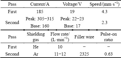
As a base material, this experiment used 2219 aluminum alloy plate with T87 heat treatment and 6.0 mm in thickness. The butt joint was created with a two-layer weld on one side. The first layer experienced direct current helium arc welding without a groove and filler metal. The second layer underwent VPTIG arc welding with ER2319 as a filler metal. The welding parameters are listed in Table 1.
Table 1 Welding parameters for double-pass TIG welding of 2219-T87 aluminum alloy
A transverse tensile test was conducted on the joint according to the standard procedure (GB/T 228.1-2010) with a crosshead speed of 2 mm/min. The dimensions of the tensile sample are shown in Fig. 1. The gauge length was 50 mm.
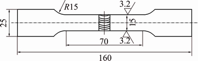
Fig. 1 Dimensions of tensile specimen (unit: mm)
DIC, a non-contact method of strain measurement, was frequently used to determine the local constitutive properties of heterogeneous materials, especially welded joints [12-14]. This work used an Aramis 4M optical measuring system developed by GOM mbH as a DIC device to measure the constitutive properties of different regions in the joints.
3 Simulation model
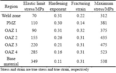
A numerical simulation of the joint’s tensile behavior was conducted using ABAQUS finite element software. With the micro-hardness testing results, the joint was divided into different regions, including the weld zone, the PMZ, the OAZ, and the base material. This method of numerical simulation is commonly used to study the global mechanical properties of welded joints [15,16]. The geometric model of the joint with the element division is shown in Fig. 2. The material parameters of various regions in the 2219-T87 TIG joint (listed in Table 2) were determined based on the DIC results, according to a detailed method described by LI et al [17]. Using the fracture strain criterion, the tensile fracture behavior of the joint was analyzed. When the equivalent plastic strain of the integral point reached its fracture strain, the corresponding element failed, initiating the fracture.
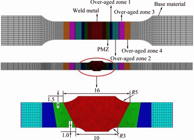
Fig. 2 Numerical simulation model of joint with weld reinforcement on both sides (unit: mm)
Table 2 Material parameters of various regions in joint
4 Results
Figure 3 shows the fracture positions of these three joints, with no weld reinforcement, weld reinforcement on two sides, and weld reinforcement on one side. And Table 3 displays the measured tensile properties of these three types of joint. The joint with two-sided weld reinforcement had the highest strength and lower elongation. The fracture occurred between the PMZ and the weld zone. The elongations of these three specimens varied from 3.79% to 5.90%. When the back reinforcement was shaved, the joint had medium strength and the highest elongation, and the fracture initiated at the PMZ. The joint without reinforcement had the lowest strength and lower elongation, and the fracture started from the weld.
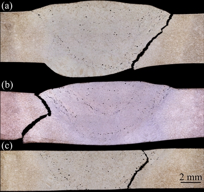
Fig. 3 Fracture positions on tensile joints with weld reinforcement on two sides (a), weld reinforcement on one side (b), and no weld reinforcement (c)
These results indicate that weld reinforcement exerts notable effects on the tensile properties of the joints. Moreover, the difference in the tensile properties among the joints with weld reinforcement on two sides demonstrates that the weld reinforcement’s shape or transition mode may influence the tensile properties of the joints.
5 Predicting effects of weld reinforcement
According to the weld shape measuring results, the height of the weld reinforcement remained nearly constant, while the weld toe shape was quite different. In some of the joints, the surface transited directly from the plate to the weld. We called this mode as the direct transition mode with angle θ. In other joints, the surface transited into featured curvature. We called this mode as the curve transition mode with radius r. The shapes of the weld reinforcements can be classified into four simple types, as shown in Fig. 4. In the simulation model, the shape at the weld toes was described by two parameters, radius r and angle θ. In this work, the effects of the weld reinforcement’s transition mode as described by θ and r on the joint’s strain distribution, nominal stress, and elongation at crack initiation were investigated.
Furthermore, the optical microstructure revealed that the joints’ weld toe positions were also different. The weld toe may be located at the juncture of the weld and the PMZ or at the PMZ. The effects of the weld toe position on the tensile behavior of the joint were also analyzed through the numerical simulation method.
Table 3 Tensile properties of base materials and three kinds of joints
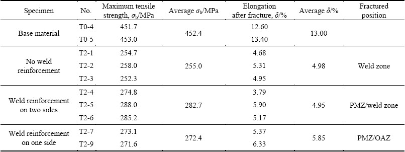
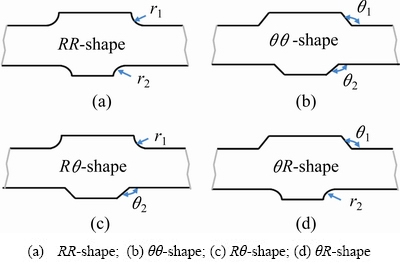
Fig. 4 Shapes of weld reinforcements
5.1 Joints with RR-shape and Rθ-shape weld reinforcements
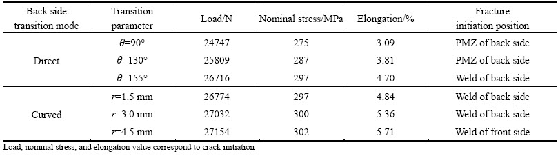
We investigated the tensile behavior of joints with different back reinforcement transition modes, given that the weld reinforcement of the front side transited with a R5 mm curve. Figure 5 shows the equivalent plastic strain distributions on the central cross-section of the joints at the moment of crack initiation (first element failure). The relevant load, nominal stress, and elongation at fracture initiation are listed in Table 4.
Plastic strain was concentrated around the weld toes (see Fig. 5). The deformation of the weld was higher than in other regions of the joints, and it was affected by the transition mode of the back weld reinforcement. The deformation of the weld was the smallest when the back reinforcement transited with θ=90° (Fig. 5(a)). In contrast, when the back reinforcement transited with r=4.5 mm, the deformation of the weld was at a maximum (Fig. 5(d)). These results can be explained as follows. The concentrated stress around the weld toe was triaxial. The stress triaxiality and concentration in the back weld toe transited with θ=90° were higher than those transited with r=4.5 mm. The fracture strain always decreased with the increase of the triaxiality. Thus, the joint in Fig. 5(a) fractured early before the weld getting enough deformation.
For different joints, the strain concentrations and weld deformations were different, meaning that nominal stress and joint elongation were also different. The nominal stress and elongation of joints with Rθ-shape weld reinforcement were lower than those with the RR-shape, and the values decreased with decreasing θ. For joints with RR-shape weld reinforcements, smaller r values produced less nominal stress and elongation. The fracture initiation position also varied with the transition mode of the back weld reinforcement. When the weld reinforcement transited directly at 90° and 130°, the fracture initiation position was located in the PMZ on the back side. When the weld reinforcement transited with curvature of 4.5 mm in radius, the fracture initiated in the weld metal on the front side. The other joints fractured in the weld metal on the backside.
The greatest difference in nominal stress at fracture initiation caused by the back reinforcement transition modes was (302-275)/275=9.8%, and the greatest difference in elongation was (5.71-3.09)/3.09= 84.8%.
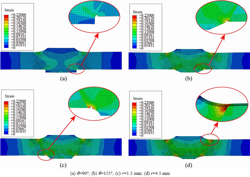
Fig. 5 Equivalent plastic strain distributions on central cross-section of joints at fracture initiation with direct (a, b) or curve (c, d) transition of back weld reinforcement (front reinforcement transition radius r=5 mm)
Table 4 Tensile results of joints with Rθ-shape and RR-shape weld reinforcement (front reinforcement transition radius r=5 mm)
5.2 Joints with θθ-shape and θR-shape weld reinforcements
We also studied the tensile behaviors of joints with different back reinforcements, given that the front reinforcement transited at 145°. The relevant values for load, nominal stress, and elongation at fracture initiation are listed in Table 5.
Table 5 Tensile results of joints with θθ-shape and θR-shape weld reinforcements (front reinforcement transition angle θ=145°)
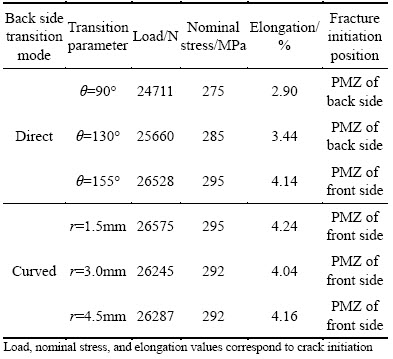
The transition mode of the back weld reinforcement also produced notable effects on load and elongation. Joints with directly-transiting back reinforcement had lower nominal stress and elongation, especially when θ was 90° and 130°. Stress and elongation decreased with decreasing θ. Joints with curved back reinforcement transitions had higher values for nominal stress and elongation. Radius r had little effect on stress and elongation, because the fracture initiated from the front side. The fracture initiation position also varied with the transition mode of the back weld reinforcement. When the weld reinforcement transited directly at 90° and 130°, the fracture initiated in the PMZ on the back side. For the other joints in Table 5, the fracture initiation positions were in the PMZ on the front side.
The maximum difference in nominal stress at fracture initiation caused by the back reinforcement transition modes was (295-275)/275=7.3%, and the maximum difference in elongation was (4.24-2.90)/ 2.90=46.2%.
A comparison of the tensile results of joints with curved transitioning (r=5 mm) front reinforcements and direct transitioning (θ=145°) front reinforcements revealed that the former group had higher values for nominal stress and elongation when the back reinforcements were the same. This result implied that the transition mode of the front reinforcement exerted obvious effects on nominal stress and elongation at fracture initiation. Directly transiting front weld reinforcement was found to be detrimental to the tensile properties. The joint with front reinforcement of θ=145° and back reinforcement of θ=90° had the lowest nominal stress and elongation. Within the 12 computed cases, the greatest difference in nominal stress at fracture initiation was (302-275)/275=9.8%, and the greatest difference in elongation was (5.71-2.90)/2.90=96.9%.
Based on the results described above, we can conclude that the transition mode of the weld reinforcement produced notable effects on both nominal stress and elongation at fracture initiation, especially elongation of the joints. These simulation results reflect the variation in the experimental results, in which joint elongation with weld reinforcement on two sides varied from 3.77% to 5.90%, and tensile strength varied from 274.8 MPa to 288 MPa (see Table 3). The joint with two-sided directly transitioning weld reinforcement had the lowest nominal stress and elongation, while the joint with curved transiting weld reinforcement had higher nominal stress and elongation. The smaller the value of θ or r was, the lower the stress and elongation were. When the weld reinforcement transition angle θ on one side of the joint was smaller than 155°, the fracture initiated from the PMZ around the weld toe. When the two-sided weld reinforcement transited with a curve, the fracture initiated from the weld metal around the weld toe. The fracture of the joint is related with the stress concentration and the materials’ mechanical properties around the weld toe. The influence mechanism of the weld toe shape on the fracture behavior of the joint needs further research.
5.3 Effects of weld toe position
We calculated the tensile behavior of different joints, in which the front weld toe position varied among the weld, juncture, and PMZ (Fig. 6) while the front weld reinforcement transited with θ value of 145°. The nominal stress and elongation at fracture initiation are given in Table 6. The data demonstrated that when the back weld reinforcement transited with a radius of 4.5 mm, the fracture initiated from the front side. The weld toe position on the front side had some effect on nominal stress and a stronger effect on elongation. The joints with the weld toe located in the weld metal or in the PMZ had greater elongation than joints with the weld toe located at the juncture of the weld metal and the PMZ.
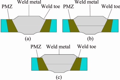
Fig. 6 Schematic diagrams of joints with weld toes located in weld metal (a), at juncture of weld metal and PMZ (b), and in PMZ (c)
Table 6 Effects of front weld toe position (front weld reinforcement transition at 145°)
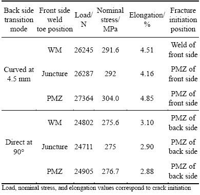
When the back weld reinforcement transited at an angle of 90°, the position of the front weld toe had little effect on the nominal stress and elongation because the fracture initiated from the PMZ on the back side. These results indicated that the position of the weld toe had some effects on the nominal stress and an even stronger effect on the elongation when the fracture initiated from the same side. Joints with weld toes located in the weld metal or in the PMZ exhibited greater elongation than joints with weld toes located at the juncture of the weld metal and the PMZ.
6 Conclusions
1) The results of these experiments and simulations indicated that the transition mode of the weld reinforcement exerted notable effects on the tensile strength and elongation of the joint, as well as the nominal stress and elongation of the joint at fracture initiation, with elongation experiencing especially strong effects. The greatest relative difference in elongation was 46.2% according to the experiment results and 96.9% according to the simulations.
2) The joint with two-sided directly transiting weld reinforcement had the lowest nominal stress and elongation, while the joint with curved transitioning weld reinforcement had higher nominal stress and elongation. The smaller the value of θ or r was, the lower the stress and elongation were.
3) The position of the weld toe had some effects on nominal stress and elongation at fracture initiation when the fracture initiated from the same side. Joints with weld toes located in the weld metal or in the PMZ exhibited greater elongation than joints with weld toes located at the juncture of the weld metal and the PMZ.
References
[1] XU Wei-feng, LIU Jin-he, LUAN Guo-hong, DONG Chun-lin. Microstructure and mechanical properties of friction stir welded joints in 2219-T6 aluminum alloy [J]. Materials & Design, 2009, 30(9): 3460-3467.
[2] XU Wei-feng, LIU Jin-he, LUAN Guo-hong, DONG Chun-lin. Microstructures and mechanical properties of friction stir welded aluminum alloy thick plate [J]. Acta Metallurgica Sinica, 2008, 44(11): 1404-1408. (in Chinese)
[3] VENKATA N G, SHARMA V M J, DIWAKAR V, SREE KUMA K, PRASAD R C. Fracture behavior of aluminium alloy 2219-T87 welded plates [J]. Science and Technology of Welding and Joining, 2004, 9(2): 121-130.
[4] WANG Zhu-tang, TIAN Rong-zhang. Aluminum alloy and its manufacturing [M]. 2nd ed. Changsha: Central South University Press, 2000: 221. (in Chinese)
[5] LI Quan, WU Ai-ping, ZHAO Yue, WANG Guo-qing, YAN Dong-yang, WU Hui-qiang. Fracture behavior of double-pass TIG welded 2219-T8 aluminum alloy joints under transverse tensile test [J]. Transactions of Nonferrous Metals Society of China, 2015, 25(6): 1794-1803.
[6] HUANG C, KOU S. Partially melted zone in aluminium welds: Solute segregation and mechanical behaviour [J]. Welding Journal, 2001, 80(9): 9-17.
[7] HUANG C, KOU S. Partially melted zone in aluminum welds: Liquation mechanism and directional solidification [J]. Welding Journal, 2000, 79(5): 113-120.
[8] SRINIVASA R K, MADHUSUDAN R G, PRASAD R K. Studies on partially melted zone in aluminium-copper alloy welds: Effect of techniques and prior thermal temper [J]. Materials Science and Engineering A, 2005, 403(1): 69-76.
[9] LI Quan, WU Ai-ping, LI Yan-jun, WANG Guo-qing, YAN Dong-yang, LIU Juan. Influence of temperature cycles on the microstructures and mechanical properties of the partially melted zone in the fusion welded joints of 2219 aluminum alloy [J]. Materials Science and Engineering A, 2015, 623: 38-48.
[10] NUNES A C Jr, NOVAK H L. Weld geometry strength effect in 2219-T87 aluminum [R]. Washington, D.C.: NASA Marshall Space Flight Center, 1981.
[11] GORDON S. An investigation into geometry and microstructural effects upon the ultimate tensile strengths of butt welds [R]. Washington, D.C.: NASA Marshall Space Flight Center, 1992.
[12] LOCKWOOD W D, REYNOLDS A P. Simulation of the global response of a friction stir weld using local constitutive behavior [J]. Materials Science and Engineering A, 2003, 339(1-2): 35-42.
[13] LEITAO C, GALVAO I, LEAL R M, RODRIGUES D M. Determination of local constitutive properties of aluminium friction stir welds using digital image correlation [J]. Materials & Design, 2012, 33(0): 69-74.
[14] BOYCE B L, REU P L, ROBINO C V. The constitutive behavior of laser welds in 304L stainless steel determined by digital image correlation [J]. Metallurgical and Materials Transactions A, 2006, 37(8): 2481-2492.
[15] GENEVOIS C, DESCHAMPS A, VACHER P. Comparative study on local and global mechanical properties of 2024 T351, 2024 T6 and 5251 O friction stir welds [J]. Materials Science and Engineering A, 2006, 415(1-2): 162-170.
[16] SIMAR A, BRECHET Y, de MEESTER B, DENQUIN A, PARDOEN T. Microstructure, local and global mechanical properties of friction stir welds in aluminium alloy 6005A-T6 [J]. Materials Science and Engineering A, 2008, 486(1-2): 85-95.
[17] LI Yan-jun, LI Quan, WU Ai-ping, MA Ning-xu, WANG Guo-qing, MURAKAWA H, YAN Dong-yang, WU Hui-qiang. Determination of local constitutive behavior and simulation on tensile test of 2219-T87 aluminum alloy GTAW joints [J]. Transactions of Nonferrous Metals Society of China, 2015, 25(9): 3072-3079.
焊缝余高对2219-T87铝合金TIG焊接头拉伸行为及力学性能的影响
王国庆1,李 权2,李艳军3,4,吴爱萍3,4,麻宁绪5,鄢东洋1,吴会强1
1. 中国运载火箭技术研究院,北京 100076;
2. 首都航天机械公司, 北京 100076;
3. 清华大学 机械工程系,北京 100084;
4. 清华大学 先进成形制造教育部重点实验室,北京 100084;
5. Joining and Welding Research Institute, Osaka University, Osaka, Ibaraki 567-0047, Japan
摘 要:运载火箭燃料贮箱通常采用2219-T87铝合金钨极氩弧焊(TIG)生产。由于贮箱服役时的承载环境比较严苛,TIG焊接头的余高控制是贮箱生产及其性能评价中的重要问题。采用实验和数值模拟的方法研究焊趾形状和焊趾位置对接头拉伸行为及力学性能的影响。研究结果表明,焊趾形状对接头的伸长率影响显著,数值计算的结果中伸长率最低值与最高值相差达96.9%;启裂侧焊趾处于焊缝和部分熔化区时接头伸长率高于焊趾处于焊缝与部分熔化区交界处的。
关键词:拉伸强度;焊缝余高;2219-T87铝合金;TIG焊;数字图像相关(DIC)技术
(Edited by Xiang-qun LI)
Corresponding author: Ai-ping WU; Tel: +86-10-62773859; E-mail: wuaip@tsinghua.edu.cn
DOI: 10.1016/S1003-6326(17)60002-5

