Path planning for UAVs formation reconfiguration based on Dubins trajectory
��Դ�ڿ������ϴ�ѧѧ��(Ӣ�İ�)2018���11��
�������ߣ������� LU Ya-fei(³�Ƿ�) �ָ�ΰ ���� ����� �־���
����ҳ�룺2664 - 2676
Key words��unmanned aerial vehicles; formation reconfiguration; path planning; Dubins trajectory; particle swarm optimization
Abstract: Multiple UAVs are usually deployed to provide robustness through redundancy and to accomplish surveillance, search, attack and rescue missions. Formation reconfiguration was inevitable during the flight when the mission was adjusted or the environment varied. Taking the typical formation reconfiguration from a triangular penetrating formation to a circular tracking formation for example, a path planning method based on Dubins trajectory and particle swarm optimization (PSO) algorithm is presented in this paper. The mathematic model of multiple UAVs formation reconfiguration was built firstly. According to the kinematic model of aerial vehicles, a process of dimensionality reduction was carried out to simplify the model based on Dubins trajectory. The PSO algorithm was adopted to resolve the optimization problem of formation reconfiguration path planning. Finally, the simulation and vehicles flight experiment are executed. Results show that the path planning method based on the Dubins trajectory and the PSO algorithm can generate feasible paths for vehicles on time, to guarantee the rapidity and effectiveness of formation reconfigurations. Furthermore, from the simulation results, the method is universal and could be extended easily to the path planning problem for different kinds of formation reconfigurations.
Cite this article as: CHEN Qing-yang, LU Ya-fei, JIA Gao-wei, LI Yue, ZHU Bing-jie, LIN Jun-can. Path planning for UAVs formation reconfiguration based on Dubins trajectory [J]. Journal of Central South University, 2018, 25(11): 2664�C2676. DOI: https://doi.org/10.1007/s11771-018-3944-z.

J. Cent. South Univ. (2018) 25: 2664-2676
DOI: https://doi.org/10.1007/s11771-018-3944-z

CHEN Qing-yang(������)1, LU Ya-fei(³�Ƿ�)1, JIA Gao-wei(�ָ�ΰ)1,
LI Yue(����)2, ZHU Bing-jie(�����)1, LIN Jun-can(�־���)1
1. College of Aerospace Science and Engineering, National University of Defense Technology,Changsha 410073, China;
2. Department of Airborne Vehicle Engineering, Naval Aeronautical and Astronautical University,Yantai 264001, China
 Central South University Press and Springer-Verlag GmbH Germany, part of Springer Nature 2018
Abstract: Multiple UAVs are usually deployed to provide robustness through redundancy and to accomplish surveillance, search, attack and rescue missions. Formation reconfiguration was inevitable during the flight when the mission was adjusted or the environment varied. Taking the typical formation reconfiguration from a triangular penetrating formation to a circular tracking formation for example, a path planning method based on Dubins trajectory and particle swarm optimization (PSO) algorithm is presented in this paper. The mathematic model of multiple UAVs formation reconfiguration was built firstly. According to the kinematic model of aerial vehicles, a process of dimensionality reduction was carried out to simplify the model based on Dubins trajectory. The PSO algorithm was adopted to resolve the optimization problem of formation reconfiguration path planning. Finally, the simulation and vehicles flight experiment are executed. Results show that the path planning method based on the Dubins trajectory and the PSO algorithm can generate feasible paths for vehicles on time, to guarantee the rapidity and effectiveness of formation reconfigurations. Furthermore, from the simulation results, the method is universal and could be extended easily to the path planning problem for different kinds of formation reconfigurations.
Key words: unmanned aerial vehicles; formation reconfiguration; path planning; Dubins trajectory; particle swarm optimization
Cite this article as: CHEN Qing-yang, LU Ya-fei, JIA Gao-wei, LI Yue, ZHU Bing-jie, LIN Jun-can. Path planning for UAVs formation reconfiguration based on Dubins trajectory [J]. Journal of Central South University, 2018, 25(11): 2664�C2676. DOI: https://doi.org/10.1007/s11771-018-3944-z.
1 Introduction
The intelligent and autonomous cooperation of multiple UAVs operating in a team/swarm offers revolutionary capabilities and improves situation awareness, significant reductions in manpower and cost efficiency. Specific applications of cooperating UAVs include, but are not limited to, border patrol, search and rescue, surveillance, mapping, and environmental monitoring. In these applications, a group of UAVs becomes to be efficiently and optimally planned in order to cooperatively achieve their mission [1�C3].
Formation reconfiguration was inevitable during the flight of cooperating UAVs, when the mission was adjusted or the environment varied [4]. Path planning for multiple UAVs during formation reconfiguration flight was very difficult under complicate constrains and detailed tasks requirement, including the kinematic/dynamic constraints of vehicles, the synchronization of timing, and collision-avoidance requirement.
The problem of formation flight for UAVs has been researched for several decades. Since 1993, a leader-wingman configuration has been researched [5, 6], and a proportional-integral (PI) controller was presented, to solve nonlinearities in the formation dynamics. A formation flight control of two F/A-18 aircrafts was implemented by JOHNSON et al [7] in the autonomous formation flight (AFF) project of NASA Dryden Flight Research Center in 2001. A vision-based formation flight test was implemented by GU et al [8]. A fixed-wing UAV was designed as the leader, while a rotary-wing vehicle as a follower. A formation flight test using three fixed-wing UAVs has been carried out by LI et al [9], and differential global position system (DGPS) was equipped to achieve high-precision positioning. A cooperative path planning method was proposed by QI et al [10], to resolve the rendezvous of multiple UAVs. A mission planning system based on path prediction algorithm for multiple UAVs is presented by YUAN et al [11], to achieve the integral framework of task assignment and path planning. The optimal path is computed by improved A* path prediction algorithm. The B-spline method is adopted to smooth the flight path. Based on a hierarchical strategy, a coordination trajectory planning method for multiple UAVs was proposed by ERGEZER [12], in which route planning, coordination control and trajectory control were defined. The genetic algorithm (GA) path planning method was researched by GAO et al [13], to maximize the collected information from desired regions (DR), while avoiding forbidden regions (FR) violation, and reaching the destination. An intelligent method based on Voronoi diagram and ant colony optimization (ACO) algorithm was proposed by ZHANG et al [14], to realize collaborative path planning of multiple unmanned aerial vehicles (UAV) under radar threatening environment. Besides the intelligent algorithms, some basic optimization algorithms were also adopted to the path planning problem. Multiple UAVs attack on multi-target coordinately was researched by CHEN et al [2]. The artificial potential method with the additional control force was used for path planning by MANYAM et al [15].
From the review of the literatures, the mathematical model for multi-UAVs path planning is usually a high-dimensional problem. The computation process is complicated and is difficult to satisfy the real time requirement. In order to realize high-efficient, real time and on-line path planning for formation configuration, a path planning method based on Dubins trajectory and particle swarm optimization (PSO) algorithm is presented in this paper. The Dubins trajectory is used to realize dimensionality reduction for the complicated path planning problem. The intelligent random search algorithm of PSO is adapted to the path solving process, which is efficient for nonlinear, non-differentiable optimization problems.
Taking the typical formation reconfiguration from a triangular penetrating formation to a circular tracking formation for example, the demonstration of formation reconfiguration for target observation is given in Figure 1. At the initial state, three vehicles are patrolling along an expected trajectory with the triangular formation. A command is sent to the vehicles at some point, and three vehicles are asked to form a circular formation around a special target, and to keep observing the target simultaneously. The circular formation is an effective configuration for target observation and target positioning. The triangular and circular formation reconfiguration process is a typical and useful case for formation control.
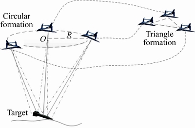
Figure 1 Demonstration of typical task of target observation by three vehicles
This paper is organized as follows: In Section 2, the model of path planning for formation reconfiguration is built. According to the kinematic model of aerial vehicles, a process of dimensionality reduction was carried out, to simplify the model based on Dubins trajectory in Section 3. The PSO algorithm was adopted to resolve the optimization problem of formation reconfiguration path planning in Section 4. Finally, the simulation and vehicles flight experiment is executed in Sections 5 and 6. Conclusions are given in Section 7.
2 Model of path planning for formation reconfiguration
2.1 UAV navigation model
A navigation model of the UAVs is indispensable to solve the path planning problem for formation reconfiguration. A penetrating and surveillance mission is carried out using multi- UAVs. Assume that the altitude change of UAVs is neglected during the formation reconfiguration from a triangular formation to a circular formation. The flight of UAVs is only considered in the horizontal plane. The typical navigation model in the horizontal plane I�CXY is shown in Figure 2, where vt denotes the ground speed of the UAV and ��t denotes the yaw angle with respect to the X axis.
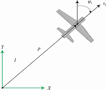
Figure 2 Typical navigation model of vehicles
In the inertial frame I�CXY in the horizontal plane, the kinematics of the UAVs are modeled using first order dynamics and are given by [16]
 (1)
(1)
where a represents the lateral acceleration, which mainly affects the lateral maneuver of the vehicle; (x, y, z) denotes the UAV position coordinates in the inertial frame. On the level flight state, the state of vehicles can be defined as (x, y, z, ��), including three position coordinates and one orientation angle.
2.2 Path planning model for formation reconfiguration
Path planning can be defined as finding a route to visit a given set of points or areas under some constraints. In order to model the path planning problem for multi-UAV formation reconfiguration, several basic terms are defined below, including the planning space, motion trajectory and the maneuver ability constraints.
2.2.1 Representation of planning space
To find feasible paths for vehicles, the first step is to represent the flight space of vehicles. Typical representations may be discrete grid maps, or continuous space. In the paper, the motion space in the horizontal plane is represented as 
2.2.2 Representation of trajectory
The planned trajectory can be represented by some patterns, such as an analytic function F=f(x, y), or many discrete points on the desired trajectory.
In the paper, the path trajectory is searched with Dubins, which is a sequences composed of straight lines and circular arcs. Therefore, the planning trajectory is represented simply and effectively as (S, P1, P2, ��, Pm�C1, G), where S is the starting state, G is the target state, and Pi represents the key waypoint along the path. A demonstration of a planed trajectory is given in Figure 3. The path in Figure 3 can be expressed by (S, P1, P2, P3, P4, G), including the starting point state S=(xs, ys, ��s), the target point state G=(xG, yG, ��G), two arc path points P1 and P4 demonstrated in blue, and two straight path points P2 and P3 demonstrated in red. The arc path points are expressed as P1,4=(x1,4, y1,4, ��1,4, ��1,4), including the center point coordinates, radius of the circle and the orbit angle. The straight path is tangential with the connect arcs, and the straight path points are expressed with the position coordinates as P2,3=(x2,3, y2,3).
2.2.3 Agent and mission constraints
The formation reconfiguration path searching process is not only subjected to the kinematic and dynamic constraints of UAVs, but also the task requirements, timing constraints and collision-avoidance requirements between vehicles. These constrains are analyzed in detail as follow.
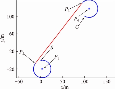
Figure 3 Demonstration of representation method of trajectory
1) Kinematic constraint of vehicles
The minimal turning radius is considered for the kinematic constraint of fix-wing UAVs, which is subjected to the maximal roll angle and the flight speed as:
 (2)
(2)
where g is the gravitational acceleration; fmax is the maximal roll angle allowed for vehicles; vt represents the ground speed of the UAV. The basic formula should be guaranteed for every point on the path as R>Rmin.
2) Constraints of task requirement
The constraints of task requirement include the space and time items. During formation reconfiguration, the vehicles are always required to arrive some positions/attitudes with critical time constraints. The task constraints are expressed as:
 (3)
(3)
where GiT is the required state of the ith UAV at the formation time T; n is the number of vehicles in the formation. For the target observation mission in Figure 1, three vehicles should arrive at the desired circle at the same time, and be distributed uniformly in space with equal angle of 2��/3. Furthermore, the pose directions of UAVs are also expected to be tangential to the circle at same heading (clockwise or anticlockwise).
The flight time can be calculated as:
 (4)
(4)
where li is the length of the planned path for the ith vehicle. [vmin, vmax] denotes the scope of the ground speed of vehicles.
3) Safety requirement
For the vehicles in the formation, the distances among UAVs at certain time should be guaranteed as:
 (5)
(5)
where dijt is the distance between the ith vehicle and the jth vehicle at time t, and dmin is the minimal safe distance for vehicles.
2.2.4 Object function
An appropriate object function is required to solve the optimization problem. Several object functions, including the consumed energy, the length of the path and the consumed time, are usually used for path planning problem. The time requirement is critical in the target observation mission, especially for time critical target observation (the window for a missile falling point observation mission could be several seconds). Therefore, the object function is selected to minimize the forming time of UAVs to the circular tracking formation. The detailed formula can de expressed as:
 (6)
(6)
These results above are combined together, to provide an overview of the path planning model for formation reconfiguration:

 (7)
(7)
where R is the radius of any points on the planned paths.
3 Dimensionality reduction based on Dubins trajectory
The algorithm of the path planning model for formation reconfiguration in Eq. (7) is a multi-dimensional problem. In order to simplify the problem and improve the solve efficiency, the Dubins trajectory is adopted to reduce the dimensionality of Eq. (7).
3.1 Dubins trajectory
The Dubins trajectory is proposed to solve the shortest path from the starting point with initial prescribed heading to the final position and heading, with exactly three paths segments which are either arcs of circles with a minimal radius or straight lines segment [17�C19]. The four different configurations for the Dubins paths are arranged as shown in Figure 4.
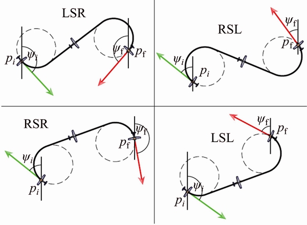
Figure 4 Four different configurations for Dubins paths
As shown in Figure 4, the Dubins paths are composed by two curved segments and a straight line segment. The four cases of Dubins paths are LSL, LSR, RSR, RSL, in which L stands for anticlockwise direction, R stands for clockwise direction and S for straight.
According to the Dubins trajectory in Figure 4, the shortest path between the starting point with initial pose and the target point with required direction, which is usually constrained by the minimal radius, can be obtained by comparing the length of the four configurations.
3.2 Selection of optimization variables
In order to process the mission demonstrated in Figure 1, three vehicles should arrive at the desired circle at the same time, with an angle at center of 2��/3 from each other. For the given geometric characteristics and the position of the target, the maximum observation orbit including the center, the height and radius R0 can be determined. Furthermore, the desired positions of three vehicles can be demonstrated with the orbit radius R0 and the rotational angle ��0i in Figure 5 and calculated as follows.
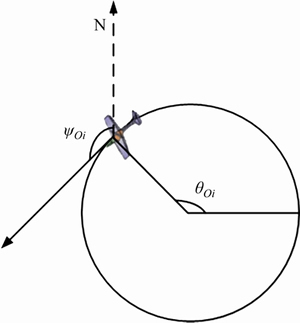
Figure 5 Representation of target position by redefined variables
 (8)
(8)
where (Ox, Oy) is the position of the target to be observed; Ro is the expected radius and ��oi denotes the rotation angle of the ith vehicles around the target. Given the rotational angle of the 1th vehicle, the rotational angle of other vehicles can be expressed as
 (9)
(9)
The target heading for the vehicles to form the formation (��Oi) can also be determined from ��Oi, as shown in Figure 5. When the formation is expected to fly along the anticlockwise direction, ��Oi=��Oi. However, when the formation is expected to fly along the clockwise direction, ��Oi+��Oi=��.
According to Eqs. (8) and (9), the target states of three vehicles ��Oi can be only determined with the rotational angle of the 1th vehicle ��O1, and then, the coordinates of three vehicles (xfi, yfi, ��oi) can be determined. In order to avoid the unsolvable problem with constant radius in Dubins trajectory, the turning radius of three vehicles ��i is also selected as the optimization variable with the angle of the 1th vehicle ��O1. In summary, the optimization variables are selected as ��O1, ��1, ��2 and ��3 for the following solvation.
3.3 Dimensionality reduction
According to the optimization variables, including ��O1, ��1, ��2 and ��3, Dubins trajectory is adopted to reduce the dimensionality of path planning model for formation reconfiguration in this section.
With the initial configuration and the expected target configuration mentioned above, the centers of the circles corresponding to the Dubins trajectory can be calculated as:
 (10)
(10)
where (xRi, yRi), (xLi, yLi,), (xRf, yRf), and (xLf, yLf) are the centers of the turning circles to the initial and target configuration in right and left direction, respectively; ��i is the turning radius; ��i and ��Oi are the heading angles as shown in Figure 6. The shortest Dubins path can be obtained by comparing the center distance of four different configurations.
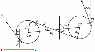
Figure 6 Demonstration of RSL-type Dubins path
Taking the RSL type in Figure 6 for example, the length of the Dubins path can be calculated as:
 (11)
(11)
where d is the distance between the two tangent points, and �� can be calculated as:
 (12)
(12)
Other types of Dubins curves can be derived in the same way. Because �� is a known variable and ��Oi can be determined by ��Oi, the length of the planned path can be calculated with the optimization variables of ��O1 and ��i. The path planning model for formation reconfiguration in Eq. (7) is simplified with Dubins trajectory as:
 (13)
(13)
4 Searching process based on PSO algorithm
From the 1990s, the PSO algorithm has been widely used in the optimization process of nonlinear, non-differentiable and multiple peak value problems [20]. Compared to the genetic algorithm, no complicated crossover and mutation operations is required. According to the problem in Eq. (13), the number of free decision variables is not large. Applying the PSO algorithm can get an excellent parallel performance. So, the PSO algorithm is adopted in the paper, to find feasible results for the path planning problem.
Firstly, m particles of the angle ��o1 are sampled uniformly on the desired circle, to generate the initial population. The sampled values are denoted as ��k (k=1, 2, ��, m). According to the goal function, the fitness for the particles can be computed. Assume that the previous best value for particle k is Pk, and the best value for the swarm found so far is Pg. Thus, the update process for the positions and velocities of the particles is:
 (14)
(14)
where vk is the velocity for particle k to move around; q is the iteration number; r1 and r2 are two independent random numbers. The random variables are designed to guarantee the diversity of the population. They are uniformly distributed in the range of [0, 1]. �� is an inertia weight, which is used to determine the global wide-range exploitation and local nearby exploration abilities. c1 and c2 are learning factors in the algorithm, which are two constant variables.
Through the comparison of the fitness for all particles, the update process shown in Eq. (14) is carried out iteratively, until the optimal value is found.
With the analysis above, the basic algorithm of path planning for formation reconfiguration can be summarized as follows. The algorithm is corresponding to the formation transform from triangle to circular. For the case from circular to triangle, similar algorithm can be designed.
5 Simulation results
To verify the proposed method, simulations were carried out. The target observation experiment was designed. Moreover, to verify the universality of the proposed method, the reconfiguration process from the circular formation to the triangular formation after observing was also carried out. The free variables in the simulation were not limited to the angle, as derived above. In another aspect, a path following simulation was carried out simultaneously, to verify the feasibility of the planned trajectories.
Three UAVs were patrolling along an expected trajectory with the triangular formation. A command was sent to the vehicles at the same time, and three vehicles were asked to form a circular formation around a special target simultaneously, and to keep on observing the target. To test the universality of the proposed method, after the observing process, the three vehicles were expected to return to the triangular formation and keep patrolling. The detailed simulation process is shown in Figure 7.
Algorithm 1 Path_Generation (Xi, O, ��i)
Input:
Xi (xi, yi, ��i), i=1, 2, ��, N-initial states of vehicles
O (xo, yo)-target position to observe
��i-circular radii of vehicles
Output:
Ri (S, P1, P2, ��, Pm, G), i=1, 2, ��, N-expected trajectory for vehicles
vi, i=1, 2, ��, N-expected speed for vehicles
success-the symbol to represent path finding result
Initialize:
��o1-the angle of vehicle 1 on the observing circular
Success=0-the symbol to represent path finding result
Begin
While ��t
��o1��(��o1), i=2, 3, ��, N
��oi,��i��(Xfi), i=1, 2, ��, N-computation of possible target states for vehicles
Xi, Xfi��(Ri), i=1, 2, ��, N-computation of Dubins paths for vehicles
for all i, j:1 to N do
if then
then
success=1;
l(Ri)��(vi), i=1, 2, ��, N-computation of expected speeds for vehicles
else
 ;
;
continue;;
end if
end for
end while
Return success, Ri (S, P1, P2, ��, Pm, G), i=1, 2, ��, N;
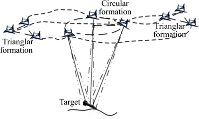
Figure 7 Simulation process (formation reconfiguration process from triangular formation to circular formation and from circular formation to triangular formation)
In the simulation, the initial positions of three vehicles were (0, 0, 0), (�C100, �C100, 0) and (100, �C100, 0), respectively. The expected target position was (300, 300), and the expected hovering radius was 200 m. The minimal turning radius was set to 150 m. The velocity scope for the vehicles was set to [15 m/s, 20 m/s]. The minimal safety distance between vehicles was 40 m. During the search process, the free variables for the reconfiguration from triangular to circular formation were ��o1, ��1, ��2, ��3, while the reconfiguration from circular to triangular formation was the expected position of vehicle 1 (xf1, yf1) and ��1, ��2, ��3. c1=c2=2 was chosen. The inertia weight was set as Eq. (15), to realize the purpose of tending to global search at the earlier stage, while tending to local optimization at the later stage [9].
 (15)
(15)
During the simulation, the search results for formation reconfiguration from the triangular formation to the circular formation are shown in Table 1. The expected trajectories were shown in Figure 8. The search results for formation reconfiguration process from the circular formation to the triangular formation are shown in Table 2, and the expected trajectories are shown in Figure 9.
Table 1 Search results for simulation, for reconfiguration process from triangular formation to circular formation
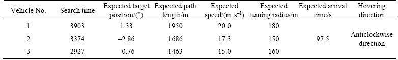
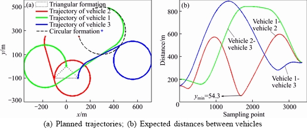
Figure 8 Planned trajectories from triangular formation to circular formation:
Table 2 Search results for simulation, for reconfiguration process from circular formation to triangular formation
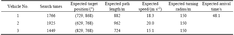
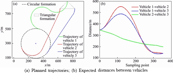
Figure 9 Planned trajectories from circular formation to triangular formation:
From the simulation results, the proposed method can find feasible paths for all vehicles, no matter from the triangular formation to the circular formation, or from the circular formation to the triangular formation. The expected time to form a new formation and the expected speed were also given. This is important to evaluate the feasibility of the planned trajectories. The expected minimal distance between vehicles was 54.3 m. This was sufficient to satisfy the safety requirement for vehicles.
In another aspect, to verify the effectiveness of the planned trajectories, the path following method in Ref. [21] is adopted, and a path following simulation is carried out. Detailed path following results was shown in Figure 10. From the simulation results shown in Figure 10(c), the vehicles can follow the planned path accurately. The cross-track error was smaller than 2 m, and the expected distance between vehicles can be guaranteed. From the results in Figure 10(b), the spent time for the reconfiguration process from the triangular formation to the circular formation was:

where t1 and t0 were the end time and start time for the reconfiguration process from the triangular formation to the circular formation, as shown in Figure 10(b). The spent time for the reconfiguration process from the circular formation to the triangular formation was:

where t3 and t2 were the end time and start time for the reconfiguration process from the circular formation to the triangular formation, as shown in Figure 10(b). The results were very close to the expected results of expected arrival time in Tables 1 and 2. Thus, the planned trajectories (including the path and the expected speed) were well suitable for the formation reconfiguration process.
Finally, during the search process for reconfiguration from the circular formation to the triangular formation, the free decision variable is the position of the vehicle, not the angle during the derived process. However, the method still can get effective results. So, the proposed method is easy to be extended to different kinds of path planning for formation reconfiguration.
Besides the simulation of three vehicles formation reconfiguration between triangular and circular formation, another simulation for ten vehicles from a circular to another circular was carried out, to verify the real time property of the proposed method, as shown in the attached video (see Supplementary file 1).
Figure 10 Following results of the planned trajectories:
6 Experimental results
To verify the proposed method, flight experiments were carried out. The experimental platform is a fixed wing vehicle, as shown in Figure 11. The span of the wing is about 2.4 m, and the length of the vehicle is about 1.6 m. The take-off weight with all electrical equipment (including the autopilot) is about 6.4 kg. The vehicle is driven by an electric brushless motor and a propeller. The low-speed flight performance of the vehicle is excellent, which is suitable for the verification experiment.
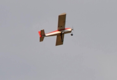
Figure 11 UAV for flight experiment
In another aspect, the control of the vehicle was performed by an autopilot researched by the group of the authors. The main CPU on the autopilot was a C2000 series TI DSP. Airspeed sensor, attitude measurement equipment and other sensors were integrated on the autopilot. The path following method was from previous work in Ref. [21], which works well under different conditions. The formation keeping and formation reconfiguration process were dealt with by different methods. The formation keeping method was based on the ��leader-wingman�� mode, and the detailed algorithm was the one from Ref. [16]. But during the formation reconfiguration process, the vehicles were flying along the replanned path individually, and the speeds of vehicles were adjusted online, to meet the need of arriving at the local target positions simultaneously.
The detailed experimental process was designed in Figure 1: three vehicles were flying with individual expected trajectories designed in advance. At a special moment, a suppositional observation target was defined and three vehicles were expected to fly along a circular trajectory around the target, just as shown in Figure 1. The vehicles were expected to arrive at the circular trajectory simultaneously, so to reduce the difficulties of formatting the expected formation on the circle by speed adjustment and so on. During the experimental process, the minimal turning radius was set to 150 m, and the radius of the circular trajectory was 200 m. The velocity scope for the vehicles was set to [15 m/s, 20 m/s], respectively. The free variables for the formation reconfiguration process were ��o1, ��1, ��2 and ��3, respectively. In the flight experiments, to guarantee the safety of vehicles, and decrease the influence of the wake, the minimum safety distance was defined as 20 m. The search results are shown in Table 3. Experimental results are shown in Figure 12. In Figure 12(b) of the ground control system (GCS), the curves represented by light red, light blue and light green were the planned Dubins trajectories, and the ones demonstrated by dark red, dark blue and dark green were the actual flight trajectories.
1) The three vehicles can follow the planned path well, and arrive at the local target with time difference less than 5 s, as shown in Figures 12(b) and (c). The arrived time (about 88 s to 93 s) was close to the computed result (88.9 s).
2) The vehicle distances between vehicles can also be guaranteed, as shown in Figure 12(d). So, the planned paths were feasible for vehicles.
3) The process was carried out online, so the proposed method can well meet the real time requirement for formation reconfiguration. This was important for the method to be extended to other applications.
When the vehicles were hovering along the circular trajectory, the other target position was given, and the reconfiguration process was carried out again. Detailed results were similar to the one above, and would not be listed again. The experimental results can be seen from the video (see Supplementary file 2) in the accessories. In the video, the process is similar to the simulation results. However, the data were based on the real vehicles flight experiments, and recorded by GCS. In the video, when three vehicles were flying along individual trajectories, no ��guidance point�� was demonstrated. When three vehicles were following the planned Dubins trajectories and keeping formation on the circle, the ��guidance points�� for the nonlinear guidance algorithm in Ref. [21] were illustrated by triangular, as shown in the video. The requirement of formation flight can well be shown by the ��guidance points��. The planned trajectories and actual following results were demonstrated by curves of different colors. In the video, when three vehicles arrived at the first circles and flied for a while, another new target was designed, and the process was carried out again, to verify the robustness of the proposed method.
Table 3 Search results for reconfiguration process to circular formation during vehicles experiments
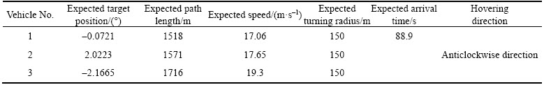
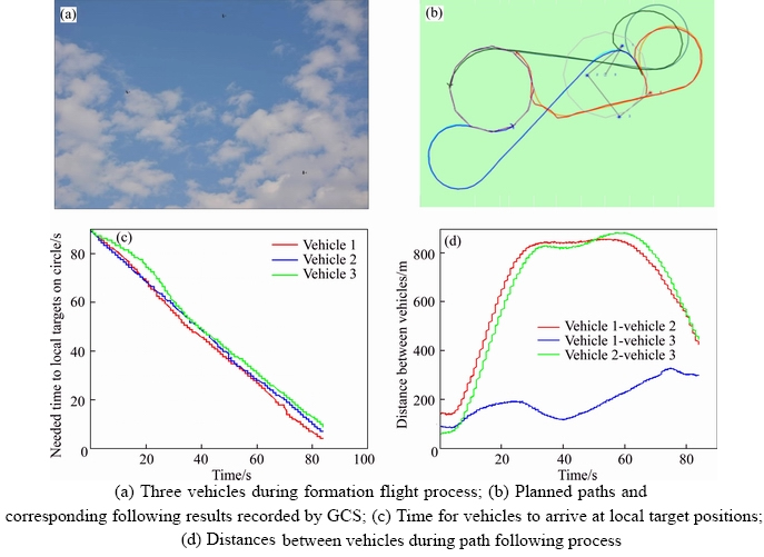
Figure 12 Results during flight experiment:
7 Conclusions and future work
Based on the Dubins trajectory and the PSO algorithm, a novel path planning method for UAVs formation reconfiguration is proposed in the paper. From the simulation results and flight experiments results, the method can find feasible paths for formation reconfiguration requirement (from the triangular formation to the circular formation, and vice versa) in time. The planned path can be tracked well (the cross-track error is smaller than 2 m), and vehicles can arrive at expected targets on time. Thus, the proposed method can resolve the path planning problem for formation reconfiguration well.
The method present in this paper could combine the advantages of the simplification of Dubins trajectory and the high efficiency of PSO algorithm, which is effective to solve the compliant and high-dimensional problem, and realize high- efficient, real time and on-line path planning for formation configuration.
Although the proposed method is useful for the path planning process, some work will be analyzed in future.
1) Up to now, the problem was researched mainly in the horizontal plane. Extending the method to the 3D environment is to be researched.
2) Some disturbances (such as winds) may make the vehicle deviate from the expected path. The related path re-plan process as well as speed adjustment operation should be researched.
3) From the experimental results, the curvature of the vehicles should be taken into account during the path planning process. For example, when the vehicle is turning left and the planned Dubins path is to turn right, the cross track error may be large. This should be also researched.
Supplementary files


File 1 File 2
References
[1] COLOMINA I, MOLINA P. Unmanned aerial systems for photogrammetry and remote sensing: A review [J]. ISPRS Journal of Photogrammetry and Remote Sensing, 2014, 92: 79�C97.
[2] CHEN Yong-bo, YU jian-qiang, SU Xiao-long, LUO Guan-chen. Path planning for multi-UAV formation [J]. Journal of Intelligent and Robotic Systems, 2015, 77: 229�C246.
[3] ZHU Xu, ZHANG Xun-xun, YAN Mao-de, QU Yao-hong. Three-dimensional formation keeping of multi-UAV based on consensus [J]. Journal of Central South University, 2017, 24: 1387-1395. DOI: 10.1007/s11771-017-3543-4.
[4] THOMAS L, STEOHEN B. Minimum-time speed optimisation over a fixed path [J]. International Journal of Control, 2014, 87(6): 1297�C1311.
[5] BUZOGANY L E, PACHTER M, DAZZO J J. Automated control of aircraft in formation flight [C]// Proc. AIAA Guidance, Navigation and Control Conf., Monterey, CA, 1993: 1349�C1370.
[6] PACHTER M,  AZZO J J, VETH M. Proportional and integral control of nonlinear systems [J]. International Journal of Control, 1996, 64(4): 679�C692.
[7] JOHNSON N, CALISE J, SATTIGERI R. Approaches to vision-based formation flight control [C]// Proceeding of IEEE Conference on Decision and Control. Atlantis, Paradise Island, Bahamas, 2004: 1643�C1648.
[8] GU Y, SEANSOR B, CAMPA G, NAPOLITANO M R, ROWE L. Design and flight testing evaluation of formation control law [J]. IEEE Transaction of Control System Technology, 2006, 14(6): 1105�C1112.
[9] LI Yue, CHEN Qing-yang, HOU Zhong-xi. Research on UAVs formation reconfiguration based on Dubins path [C]// Proceedings of 2016 IEEE Chinese Guidance, Navigation and Control Conference. Nanjing, Jiangsu, 2016: 2745�C2750. (in Chinese)
[10] QI Nai-ming, SUN Xiao-lei, DONG Cheng, YAO Wei-ran. Mission planning based on path prediction for multiple UAVs [J]. Journal of Harbin Institute of Technology, 2016, 48(4): 32�C36. (in Chinese)
[11] YUAN Shuai, LI Fei, WANG Long, ZHANG Yu. An optimal coordination trajectory planning method of multiple unmanned air vehicles based on hierarchy strategy [J]. Journal of Air Force Engineering University(Natural Science Edition), 2015, 16(2): 33�C37. (in Chinese)
[12] ERGEZER H, LEBLEBICIOGLU K. 3D Path planning for multiple UAVs for maximum information collection [J]. Journal of Intelligent and Robotic Systems, 2014, 73: 737�C762.
[13] GAO Chen, ZHEN Zi-yang, GONG Hua-jun. Collaborative path-planning of multiple UAV in radar threatening environment [J]. Journal of Applied Sciences, 2014, 32(3): 287�C292. (in Chinese)
[14] ZHANG Xiao-min, MA Pei-bei, JI Jun, ZHU Liang-ming. Cooperative planning control of multi UAV with time constraint [J]. Electronics Optics and Control, 2015, 22(9): 42�C45. (in Chinese)
[15] MANYAM G S, RATHINAM S, CASBEER D, GARCIA E. Tightly bounding the shortest Dubins paths through a sequence of points [J]. Journal of Intelligent and Robotic Systems, 2017, 88: 495�C511.
[16] CHEN Qing-yang, LI Yue. UAVs formation flight control based on following of the guidance points [C]// Proceedings of 2016 IEEE Chinese Guidance, Navigation and Control Conference. Nanjing, China, 2016: 730�C735.
[17] MADHAVAN S, ANTONIOS T, BRIAN W. Co-operative path planning of multiple UAVs using Dubins paths with clothoid arcs [J]. Control Engineering Practice, 2010, 18: 1084�C1092.
[18] HYONDONG O, SEUNGKEUN K, ANTONIOS T. Cooperative road-network search planning of multiple UAVs using dubins paths [C]// AIAA Guidance, Navigation, and Control Conference. Oregon, Portland, 2011: 1�C16.
[19] ISRAEL L, GERARDO F, SERGIO S. Dubins path generation for a fixed wing UAV [C]// 2014 International Conference on Unmanned Aircraft Systems (ICUAS). 2014: 339�C346.
[20] LIU Xiao-feng, PENG Zhong-ren, CHANG Yun-tao, ZHANG Li-ye. Multi-objective evolutionary approach for UAV cruise route planning to collect traffic information [J]. Journal of Central South University, 2012, 19: 3614�C3621.
[21] LI Yue, CHEN Qing-yang, HOU Zhong-xi. Path following method with adaptive guidance length for unmanned aerial vehicles [J]. Journal of Beijing University of Aeronautics and Astronautics, 2017, 43(7): 1481�C1490. (in Chinese)
(Edited by YANG Hua)
���ĵ���
����Dubins�켣�Ķ����˷����������ع������滮�����о�
ժҪ���������˷�������ӵ�����ı䣬�������仯ʱ����Ӷ����ع��Ĺ���һ�������Ա���ġ���Զ����˷���������Ŀ��۲�ĵ���������Զ����ع����̵�ʵʱ�����滮��������о���Ϊ�˽����ͬ״̬�����Ƕ�����Բ�ζ��α任���̵�ʵʱ�����滮���⣬���һ���ں�Dubins�켣������Ⱥ�Ż��㷨��PSO���ĺ����滮���������ȣ��Զ����˷����������ع��ĺ����滮���������ϸ������������ά����ѧģ�͡����������������˷������Ļ����˶�ѧģ�ͣ�����Dubins�켣��������ѧģ�ͽ��н�ά������ڼ���ѧģ�ͣ�����PSO�Ż��㷨����ʵʱ��⡣�ӷ�����������������Կ���������Dubins�켣��PSO�㷨�ĺ����滮���������ڶ��α任������ʵʱ��Ч�����ɿ��к��������⣬�ӷ��������Կ�����������������������չ����ͬ���ε��ع����̣���˾��нϺõ�ͨ���ԡ�
�ؼ��ʣ����˷������������ع��������滮��Dubins�켣������Ⱥ�Ż�
Foundation item: Project(61703414) supported by the National Natural Science Foundation of China; Project(3101047) supported by the Defense Science and Technology Foundation of China; Project(2017JJ3366) supported by the Natural Science Foundation of Hunan China; Project(2015M582881) supported by the China Postdoctoral Science Foundation
Received date: 2017-09-14; Accepted date: 2018-03-21
Corresponding author: CHEN Qing-yang, PhD, Lecturer; Tel: +86-15173115173; E-mail: chy1982_008@nudt.edu.cn; ORCID: 0000- 0002-5134-8184

