J. Cent. South Univ. Technol. (2011) 18: 171-176
DOI: 10.1007/s11771-011-0676-8

Torsional vibration analysis of lathe spindle system with unbalanced workpiece
GUO Rui(郭瑞), JANG Sung-Hyun, CHOI Young-Hyu
School of Mechatronics, Changwon National University, Changwon 641-773, Korea
? Central South University Press and Springer-Verlag Berlin Heidelberg 2011
Abstract: For the purpose of analyzing the torsional vibration caused by the gravitational unbalance torque arisen in a spindle system when it is machining heavy work piece, a 10-DOF lumped parameter model was made for the machine tool spindle system with geared transmission. By using the elementary method and Runge-Kutta method in Matlab, the eigenvalue problem was solved and the pure torsional vibration responses were obtained and examined. The results show that the spindle system cannot operate in the desired constant rotating speed as far as the gravitational unbalance torque is engaged, so it may cause bad effect on machining accuracy. And the torsional vibration increases infinitely near the resonant frequencies, so the spindle system cannot operate normally during these spindle speed ranges.
Key words: unbalanced work piece; gravitational unbalance torque; torsional vibration; spindle system; geared transmission
1 Introduction
When a lathe is machining heavy work piece with unbalance weight such as crankshaft, its main spindle system cannot operate in the desired constant rotating speed, because unbalance torque usually arises in the work piece. In order to keep constant operation speed against the gravitational unbalance torque, usually control motor is adopted in the spindle system with geared transmission in addition to main driving motor. However, the static pre-torque produced by the control motor is half the unbalance torque, so it may compensate at most half the unbalance torque of the work piece. The resulting rotating speed variations in the main spindle or work piece may cause undesirable or bad effects on machining accuracy.
Recently, there are some remarkable researches on torsional vibration of turning lathe spindle system with geared transmission. Especially, SARAVANAN et al [1], GAO and HAO [2], and YUAN et al [3] have focused on the torsional vibration caused by unbalancing; CHEN et al [4], HSIEH et al [5], and HUANG [6] have researched on coupled torsional vibrations; LEES [7], PATEL and DARPE [8], and NEUGEBAUER et al [9] have researched on lateral vibrations; and CHOI et al [10] have researched on the geared transmission system; and there are also lots of researches on the simplified mathematical modeling of main spindle system [11-15].
However, the torsional vibration of the spindle
system with unbalanced work piece was not taken into consideration in all the researches mentioned above. If the spindle system is added with an unbalanced work piece, the torsional vibration of the spindle system will become more complex, even though driving motor torque is not applied during constant speed operation.
For the purpose of analyzing the torsional vibration, a 10-DOF lumped parameter model was made for the spindle system with geared transmission of a lathe with unbalanced work piece. The torsional vibration of the spindle system was analyzed by using Matlab and the eigenvalue problem of the system was solved by using the elementary method [16-17]. Then, forced vibration responses of the spindle system were obtained under the driving torque together with gravitational unbalance torque.
By comparing the computed forced vibration responses for the two cases: the spindle system with and without unbalanced work piece, the effects on the torsional vibration responses of the spindle caused by the gravitational unbalance torque were able to be clarified. And the pure torsional velocity response of the spindle, which may be an important estimator for machining accuracy, was obtained and examined.
2 Theoretical vibration analyses
2.1 Mathematical modelling
From the schematic diagram of the main spindle system with geared transmission as shown in Fig.1, a 10-DOF mathematical model was made, as shown in Fig.2, where Ji represents the mass moment of inertia of the i-th equivalent rotor and kij represents the torsional spring stiffness of the shaft between the i-th and j-th equivalent rotor.
2.2 Equation of motion
The equation of motion of the system can be derived by Newton’s law as
 (1)
(1)
where J represents the inertia matrix of the system; T represents the input torque vector matrix of the system and Kt represents the torsional stiffness coefficient matrix.

Fig.1 Schematic diagram of main spindle system

Fig.2 Mathematical modeling of main spindle system
 (2)
(2)
 (3)
(3)
 (4)
(4)
where Jeqi represents the gear ratio; Tm(t) represents the driving motor torque; Tu(t) represents the unbalance torque; Tc(t) represents the control motor torque; zi represents the number of teeth of the gear.
ki is determined as
 (5)
(5)
where Gi represents the shear modulus of the i-th shaft, Ii represents the cross section area moment of inertia of i-th shaft and Li represents the length of the i-th shaft.
2.3 Gravitational unbalance torque
The gravitational unbalance torque may be caused by three reasons: journal unbalance, unbalance in crankpin and misalignment of journal.
3-dimensional (3D) model of a crankshaft, which is a workpiece, is shown in Fig.3. It can be simplified as a uniform shaft with evenly phased six unbalance weights as shown in Fig.4, where mi represents the unbalance mass of the i-th crankpin; ri represents the radius of the i-th unbalance mass; g represents the gravitational acceleration and  represents the gravity of the i-th crankpin.

Fig.3 3D model of 6 pins crankshaft
The gravitational unbalance torque of n-crankpins, Tup, can be derived as
 (6)
(6)
where  represents the phase angle of the i-th unbalance mass.
The pure torsional angular response is defined as  where θk is the kinematic angular displacement and it is much bigger than
  to ignore the
  so in the Eq.(6),
Therefore, the gravitational unbalancing torque of 6 crankpins can be expressed as


 (7)
(7)
where  and Tupi represents the gravitational
unbalance torque of the i-th crankpin.
For the convenience of computation, it is assumed that there is no loss of generality, the unbalance of the journals, uj, is 1% and the error in radius of gyration of journals, ej, is 3.5%. The resulting unbalanced torque of journals can be expressed as
 (8)
(8)
where muj represent the unbalance mass of the journal; ruj represents the radius of the unbalance mass and mj represents the mass of the journal.
The misalignment torque of journals can be expressed as
 (9)
(9)
So the resultant unbalancing torque of crankshaft in this system can be expressed as
 (10)
(10)
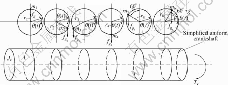
Fig.4 6-unbalance weights in simplified crankshaft
2.4 Solving equations of motion
2.4.1 Eigenvalue solution
For solving the eigenvalue problem, let T(t)=0 and assume that a solution is θ(t)=Θexp(iωt), where θ represents the maximum amplitude and ω represents frequency, then the free vibration equation of the system becomes eigenvalue problem:
Kt-ω2JΘ=0 (11)
To make the stiffness matrix symmetric, all the gear ratios in Eq.(4) are assumed unit. And Jeq1=2.35, Jeq2=1.89, Jeq3=1.48, Jeq4=1.97, Jeq5=4.25, Jeq6=86.37, Jeq7=3 612.4 (in Case 1), Jeq7=7 802.4 (in Case 2), Jeq8= 6.63, Jeq9=0.53, Jeq10=1.01 kg?m2; k12=5.4×10⁶, k23= 1.2×10⁹, k34=2.5×10⁷, k45=5.4×10⁹, k46=6.4×10⁷, k67=1.3× 10⁹, k68=2.4×10⁷, k89=4.0×10⁷, k90=6.7×10⁶.
By using Matlab, the eigenvalues for the two cases are determined, as listed in Table 1 (without work piece case) and Table 2 (with work piece case).
Table 1 Calculated eigenvalues of Case 1 (without workpiece)
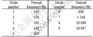
Table 2 Calculated eigenvalues of Case 2 (with workpiece)

2.4.2 Forced vibration responses
To solve the forced vibration problems, the number of teeth of gears are given as z1=25, z2=84, z4=23, z6=84, z7=24, z8=141, z9=24, z10=84, z11=23, z12=84 and z13=25. When the desired spindle speed input is given, as shown in Fig.5, the associated driving torque for the cases 1 and 2 can be determined, as shown in Fig.6.

Fig.5 Desired spindle speed input

Fig.6 Corresponding driving torque input of main motor in case 1 and case 2
Fig.7 shows the comparison of the angular velocity responses of the spindle end for cases 1 and 2. The pure torsional velocity response of the spindle, ωφ, is defined as ωφ=ω7-ωd. And the pure torsional velocity response of the spindle at period of constant spindle speed ωd=2 rad/s is also computed, as shown in Fig.8. The resultant unbalance torque, Tu(t), is obtained in the case of constant spindle speed ωd=2 rad/s and shown in Fig.9. Using the same solving method, the pure torsional vibration responses of the spindle are obtained, as shown in Fig.10.

Fig.7 Comparison of calculated angular velocity at face plate of spindle system ω7 in case 1 and case 2

Fig.8 Comparison of pure torsional velocities at period of constant spindle speed ωd=2 rad/s in case 1 and case 2

Fig.9 Resultant unbalance torque, Tu(t), at period of constant spindle speed ωd=2 rad/s
Judging from the computed pure torsional velocity response of the spindle shown in Fig.8, the spindle system cannot operate in the desired constant rotating speed if the gravitational unbalance torque is engaged.
As shown in the Fig.10, the pure torsional velocity response of the spindle increases infinitely near the spindle speed corresponding to the system resonant frequencies. And the pure torsional velocity responses of the spindle with the other spindle speeds are not so small to neglect.

Fig.10 Pure torsional vibration response ωφ of spindle
3 Conclusions
1) The spindle system of a lathe with unbalanced work piece cannot operate in the desired constant rotating speed as far as the gravitational unbalance torque is engaged.
2) The pure torsional velocity amplitude of the spindle increases infinitely near the spindle speed corresponding to the system resonant frequencies, so the spindle system cannot operate normally with these speeds.
3) The pure torsional vibrations of the spindle cannot be neglected during other spindle speed ranges, so it may cause bad effects on machining accuracy.
References
[1] SARAVANAN N, CHOLAIRAJAN S, RAMACHANDRAN K I. Vibration-based fault diagnosis of spur bevel gear box using fuzzy technique [J]. Expert Systems with Applications, 2009, 36(2): 3119-3125.
[2] GAO Wen-zhi, HAO Zhi-yong. Active control and simulation test study on torsional vibration of large turbo-generator rotor shaft [J]. Mechanism and Machine Theory, 2010, 45(9): 1326-1336.
[3] YUAN Zhen-wei, CHU Fu-lei, LIN Yan-li. External and internal coupling effects of rotor’s bending and torsional vibrations under unbalances [J]. Journal of Sound and Vibration, 2007, 299(1/2): 339-347.
[4] CHEN Rui-lin, ZENG Qing-yuan, ZHANG Jun-yan. New algorithm applied to vibration equations of time-varying system [J]. Journal of Central South University of Technology, 2008, 15(1): 57-60.
[5] HSIEH S C, CHEN J H, LEE A C. A modified transfer matrix method for the coupled lateral and torsional vibrations of asymmetric rotor-bearing systems [J]. Journal of Sound and Vibration, 2008, 312(1/2): 563-571.
[6] HUANG D G. Characteristics of torsional vibrations of a shaft with unbalance [J]. Journal of Sound and Vibration, 2007, 308(3/4/5): 692-698.
[7] LEES A W. Misalignment in rigidly coupled rotors [J]. Journal of Sound and Vibration, 2007, 305(1/2): 261-271.
[8] PATEL T H, DARPE A K. Vibration response of misaligned rotors [J]. Journal of Sound and Vibration, 2009, 325(3): 609-628.
[9] NEUGEBAUER R, DENKENA B, WEGENER K. Mechatronic systems for machine tools [J]. Journal of CIRP Annals- Manufacturing Technology, 2007, 56(2): 657-686.
[10] CHOI Y H, PARK S K, JUNG T S, KIM C S. A case study on the vibration and noise reduction in a gearbox for a lathe [C]// Proceedings of the Inter Noise, Seogwipo, 2003: 3543-3550.
[11] WIDDLE R D, KROUSGRILL C M, SUDHOFF S D. An induction motor model for high-frequency torsional vibration analysis [J]. Journal of Sound and Vibration, 2006, 290(3/4/5): 865-881.
[12] WU Jia-jang. Torsional vibration analyses of a damped shafting system using tapered shaft element [J]. Journal of Sound and Vibration, 2007, 306(3/4/5): 946-954.
[13] CHARLES P, SINHA J K, LIDSTONE G L, BALL A D. Detecting the crankshaft torsional vibration of diesel engines for combustion related diagnosis [J]. Journal of Sound and Vibration, 2009, 321(3/4/5): 1171-1185.
[14] WHALLEY R, ABDUL A A. Contoured shaft and rotor dynamics [J]. Mechanism and Machine Theory, 2009, 44(4): 772-783.
[15] PATEL T H, DARPE A K. Experimental investigations on vibration response of misaligned rotors [J]. Mechanical Systems and Signal Processing, 2009, 23(7): 2236-2252.
[16] SINGIRESU S R. Mechanical vibrations [M]. New Jersey: Pearson, 2004: 381-540.
[17] XUE Ding-yu. Computer aided control systems design using MATLAB language [M]. Beijing: Tsinghua University Press, 2006: 17-63. (in Chinese)
(Edited by LIU Hua-sen)
Foundation item: Project(10033135-2009-11) supported by the Korean Ministry of Knowledge Economy (MKE) through HNK. Co, Ltd.
Received date: 2010-04-29; Accepted date: 2010-09-22
Corresponding author: CHOI Young-Hyu, Professor; Tel: +82-55-213-3623; E-mail: yhchoi@chongwon.ac.kr

