Velocity tracking control of BLDCM based on generalized predictive control
CUI Yue-yuan(崔乐远), WANG Yin-he(王银河), HU Jun(胡钧), ZHANG Yun(章云)
(Faculty of Automation, Guangdong University of Technology, Guangzhou 510006, China)
Abstract: The velocity loop, as the intermediate loop of the brushless direct current motor (BLDCM) servo system, has the direct effect on the control precision and response speed. Due to the closed-loop transfer function of velocity loop is related to the intermediate controller and it’s difficult to convert the transfer function of velocity loop to state space dynamical equation when the structure of controller has not been determined. By focusing on the block diagram of the typical three-loops structure and considering the coupling effect between the position loop and velocity loop, then simplifying the velocity loop, a simple, effective and practical adaptive generalized predictive controller, which is based on prediction and optimization of multi-step rolling, is introduced in brushless DC motor application. Finally, simulation results show the validity of the method.
Key words: BLDCM; velocity loop; generalized predictive control; self-turning control
CLC number: TP273 Document code: A Article ID: 1672-7207(2011)S1-0304-05
1 Introduction
Brushless DC motor[1] velocity control system is the key to improve the servo system’s control precision, response speed and the control performance, the velocity loop system is mainly for increasing resistance to the variety of load disturbance and the outside interference. And the main control process is to use the position loop controller's output as the velocity controller’s reference input, and then use the output of the velocity loop controller as the current controller’s input so as to control the power electronics converter and regulate the motor armature current.
In the traditional design of the velocity loop control, generally speaking, the PI controller is usually able to meet the objective of stability in some general and simple applications. However, the BLDCM is essentially a multivariable and nonlinear system, different interference like random interference and periodic interference will appear in the control process, the control effect is not so satisfactory if using PI controller. Therefore, it’s necessary to discuss other forms of velocity control design.
With adaptive and self-learning abilities, intelligent control strategies such as fuzzy control[2], model reference adaptive control[3], sliding mode control[4] and neural networks control[5] are theoretically used in BLDCM, however, the designs are not only difficult, but also computational complex. Sliding mode control can easily lead to chattering, and it’s not easy to be promoted and applied in the actual engineering. On the other hand, these control methods do not maintain the servo system’s typical three-loops structure generally. In industrial applications, the servo system is often seen in the form of three-loops structure. Therefore, from practical angles, it’s important to design velocity loop controller under the condition of maintaining three-loops structure.
It is noted in control process that the parameters in BLDCM are almost always changing with the working environment (disturbances, random interference, etc.), therefore, using the traditional optimal control or intelligent control in this case can not always get good results. Due to the current development of digital control in practical engineering, the self-tuning control methods, which can tune automatically the parameters in BLDCM and the controller according to the changing process, are getting more and more attention by engineers. Besides, the self-tuning digital control algorithms are the simpler, more reliable and little on-line learning time, and thus they possess the better properties in implementation and control validity.
In this work, by focusing on the block diagram of the typical three-loops structure and control method and simplifying the velocity loop, a generalized predictive control method[6-12] is applied to BLDCM velocity control systems. The design process is as follows: first of all, disconnect the velocity feedback loop in the block diagram before the design, then we can get a simplified open-loop transfer function, sum it up as the basis for designing the self-tuning controller, and then, according to the results of the design, the velocity feedback loop should be recovered in the block diagram. Finally, under maintaining the velocity loop in the block diagram, the self-tuning control simulation is demonstrated and the validity is shown in the servo system.
2 Control system model and design
Consider the following the block diagram of the typical three-loops structure of BLDCM, as shown in Fig.1.

Fig.1 Typical three-loop structure of BLDCM
In Fig.1, L and R are the inductance and resistance, respectively; J is the load inertia; B is the viscous friction coefficient; KT and KE are the torque constant and back EMF constant, respectively; I is the output current; q is the rotation angle; w is the motor velocity;  is the output of velocity loop controller Cw;
 is the output of position controller CP; CI is the current loop controller.
In this work, the controller is designed only for the velocity loop, with the purpose of ensuring that the output of velocity loop tracking the position loop controller’s output, without considering the position loop controller design, the current inner loop controller uses PI control, i.e. CI=K1+K2/s=(K1s+K2)/s.
From Fig.1, it is easy to get the transfer function between the velocity controller output and the motor velocity w, i.e.
 (1)
(1)
where
B0=K1KT/(LJ2), B1=(K1KTB+K2KT J)/(LJ2), B2=K2B/(LJ2), A1=(2LBJ+K1J2+RJ2)/(LJ2), A2=(2RBJ+2K1BJ+K2J2+ LB2+KEKTJ)/(LJ2), A2=(2K2BJ+RB2+BKEKT+K1B2)/(LJ2), B2=K2B2/(LJ2).
Fig.1 shows that, due to the coupling effect between the position loop and velocity loop, the closed-loop transfer function of velocity loop is related to the controller Cw. Therefore, it’s difficult to convert the transfer function of velocity loop to state space dynamical equation when the structure of controller Cw has not been determined, and thus it means that design methods which are based on the state space dynamical equation such as adaptive fuzzy control, sliding mode variable structure control are utilized here.
On the other hand, in the usual velocity loop feedback control, controller Cw usually use the PI controller, i.e. Cw=K3+K4/s. Clearly, the output of the position loop controller Cp often according to the change of the motor velocity (usually nonlinear signal), so the constant parameters K3 and K4 cannot guarantee the velocity loop to track asymptotically a random output signal of the position loop controller. Therefore, the controller Cw is redesigned as follows.
Before making control design, the velocity feedback loop in the block diagram is disconnected and the position loop is not considered in Fig.1, and then the transfer function is simplified (Fig.2) to obtain the basis of designing the self-tuning generalized predictive controller Cw.

Fig.2 System block diagram of disconnecting velocity loop (regardless of position loop)
Generalized predictive control is a computer control strategy, which relies on mathematical models of discrete systems. It is necessary for models to deal with discrete objects. Consider the input , the output  , reference input , using zero-order holder, and the sampling period is T, The transfer function (1) can be discredited into the following ARMA model:
 =
=  (2)
(2)
The ARMA model (2) can be represented with the disturbance as follows:
 (3)
(3)
where  is white noise with the mean value of 0, variance is σ2. C(z-1) is the Hurwitz polynomial,
  and
and  are the samples for input and output.
  is the pure delay, and


 and
and
 .
.
3 Generalized predictive controller
Generalized predictive control is an important adaptive control algorithm, which is based on maintaining the minimum variance self-tuning control of online identification and the output prediction, absorbed the rolling optimization strategy of DMC[13] and MAC[14], and introduced the unequal length of prediction and control, which not only has excellent characteristics of predictive model, rolling optimization and feedback correction online, but also has excellent control performance and robustness.
In 1992, Jin[8] improved generalized predictive control algorithm, and extended it to the CARMA model predictive control algorithm, a method based on the CARMA model predictive control. According to the algorithm, this paper will apply the generalized predictive control method to a brushless DC motor velocity control system. The basic structure of applying the generalized predictive control in BLDCM velocity control system is shown in Fig.3.
From Fig.3, the control feedback loop should be recovered according to the results of generalized predictive control process control design, it is the case that the actual output of the system transmit back to the minimum variance prediction model, and forecast model output feeds back to the next objective function, and finally under the premise of the velocity loop is maintained, we can achieve the control goal for the servo system.
In the prediction model, the optimizing of the performance index involves only within a limited future time domain, while at the next sampling time, this optimization will also move over according to the time domain, thus the predictive control in every moment has a relative to the optimization performance index, to make sure the future control sequence is updated, and achieve rolling optimization. In order to make the output  transit smoothly at a certain response speed to the reference input
  , the reference trajectory is usually taken the first order smoothing model:
 (4)
(4)
where  is the reference trajectory of k+j times,
 is the soften output coefficient, and N is the predicting step length.
By using the recurrence Eq.(3), the future minimum variance prediction model is:
 (5)
(5)
where
 is the next N steps of the minimum variance prediction value at time k, j=d, d+1, …, N

is the next N step of predicting output at time k,j=d, d+1,…, N,and

 (6)
(6)
where
 ,
, .
.
It can be seen that  is completely determined by the previous control inputs and outputs.
 is the current and the future control increment vector,where
  .
.
 (7)
(7)
The elements of the matrix G is calculated by the following formula:
 (8)
(8)
where and when
 .
.
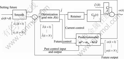
Fig.3 Basic structure of generalized predictive control
Set the minimization objective function as follows:
 (9)
(9)
where is the control weighted matrix, and
  .
.
The corresponding control increment vector is:
 (10)
(10)
Then the velocity controller's output is:
 (11)
(11)
4 Application and simulation
Select the sampling period T=0.01s, the reference input signal is a sine wave as  and a
and a
square wave signal with the amplitude of 10. The pure delay d=1, is the white noise with the mean value of 0, the variance is 0.000 1. Let C(z-1)=1+0.1 z-1. The parameters of PI controller in the inner current loop are K1=0.001 5, K2=1, respectively. The BLDCM parameters[1, 15] are L=0.008 5 H, KE=0.7 V/(rad・s-1), R=2.875 W, KT=1.2 N・m/A, B=1×10⁻³ N・m・s, J=0.8×10⁻³ kg・m2 respectively. According to Refs. [6-8], the BLDCM velocity control of the generalized predictive control algorithm can be summarized as:
Step 1 Initialization, take the initial value of the covariance matrix of recursive extended least squares method as  ,the estimated parameter vector
  ,the controller parameter N=8, the control weighted matrix is a unit matrix I8×8,the output soften coefficient α= 0.35;
Step 2 Sample the current output ω(k) and the reference trajectory ωr(k+j);
Step 3 Estimate the controller parameters by means of recursive extended least squares method. Solve the control matrix G from Eq.(7);
Step 4 Recursively calculate by Eq.(6) and construct vector ωm, and use Eq.(11) to calculate the input  ;
;
Step 5 When k→k+1, go to step 2.
The simulation results are shown in Fig.4-6 with the input signal sinusoidal signal, and square wave signal, respectively.
If taken the PI controller[1], and set K3=100, K4=0.1, in the same sampling period and the same variance of white noise, the system output is shown in Fig.7.
From Fig.7, it can be seen that under the generalized predictive controller with the square wave reference input, the output tracking error of the system is more accurate than PI case. Moreover, the controlled system has faster response than PI case.

Fig.4 Tracking results with sinusoidal reference input

Fig.5 Output of velocity system controller

Fig.6 Tracking results with square wave reference input

Fig.7 Generalized predictive control and PI control results with square wave reference input
5 Conclusions
In the BLDCM velocity control and applications, the common PI control methods for velocity loop have some weak points with the change of the motor parameters. This work describes the practical and effective method of generalized predictive control design. In the case of maintaining the velocity loop structure of servo system, the control results in this paper can not only guarantee the system robustness on dynamic process, but also have faster response speed, better control effect and smaller control errors. Meanwhile, the digital velocity control method in this paper has a small on-line calculation and easy to be realized.
References
[1] XIA Chang-liang. Brushless DC motor control system[M]. Beijing: Science Press, 2009: 57-62. (in Chinese)
[2] PENG Yun-song, JI Ye-zhang, KE Yue-zhang. Simulation of BLDCM speed control system based on PI controller with fuzzy parameter regulators[J]. Applied Mechanics and Materials, 2010, 29/30/31/32: 841-846.
[3] JI Zhi-cheng, LI Xiao-qing, SHEN Yan-xia. Model reference fuzzy adaptive approach and experiment study for brushless DC motor[J]. Transactions of China Electrotechnical Society, 2006, 21(1): 75-81.
[4] Lu Y S, Chen J S. Design of a global sliding-mode controller for a motor drive with bounded control[J]. International Journal of Control, 1995, 62(5): 1001-1019.
[5] GUO Hai-Jiao, Sagawa S J, Ichinokura O. Position sensorless driving of BLDCM using neural networks[J]. Electrical Engineering in Japan, 2008, 162(4): 64-71.
[6] XU Xian-yuan. Adaptive control theory and applications[M]. Beijing: Publishing House of Electronics Industry, 2007: 76-85. (in Chinese)
[7] PANG Zhong-hua, CUI Hong. System identification and adaptive control of the MATLAB simulation[M]. Beijing: Beihang University Press, 2009: 161-168. (in Chinese)
[8] JIN Yuan-yu. New general prediction control based on ARMAX model[J]. Control Theory and Applications, 1992, 9(4): 426-431. (in Chinese)
[9] ABU-Ayyad M, DUBAY R. Improving the performance of generalized predictive control for nonlinear processes[J]. Industrial & Engineering Chemistry Research, 2010, 49(10): 4809-4816.
[10] YANG Can, ZHU Shan-an, KONG Wan-zeng, et al. Application of generalized predictive control in networked control system[J]. Journal of Zhejiang University: Science A, 2006, 7(2): 225-233.
[11] Dumur D, Boucher P, Ramonda G. Direct adaptive generalized predictive control: Application to motor drives with flexible modes [J]. CIRP Annals―Manufacturing Technology, 2000, 49(1): 271-274.
[12] Wang W A. Direct generalized predictive adaptive control algorithm with stability guaranteed[J] Int J Adaptive Control Signal Proc, 1994, 39(5): 1052-1056.
[13] Culter C R, Ramaker B L. Dynamic matrix control: A computer control algorithm[C]//Proceedings of Joint Automatic Control Conference. SanFrancisco, 1980: WP5-B.
[14] Rouhanni R, Mehra R K. Model algorithmic control(MAC)[J]. Basic Theoretical Properties, Automatica, 1982, 18(4): 401-414.
[15] XIA Chang-liang, CAO Wei-li, SONG Peng. The speed-adjustment system of brushless DC motor based on grey PID[C]//IEEE International Conference on Automation and Logistics. Qingdao, 2008: 35-38.
(Edited by YANG You-ping)
Received date: 2011-04-15; Accepted date: 2011-06-15
Foundation item: Project (8151009001000061) supported by the Natural Science Foundation of Guangdong Province, China; Project (8351009001000002) supported by the Natural Science Joint Research Program Foundation of Guangdong Province, China
Corresponding author: CUI Yue-yuan, Master; Tel: +86-13570535104; E-mail:cyycly777@126.com

