ʯīϩƬ���Ӷ�AZ31þ�Ͻ���������ǿ�����ټ�벻�����ͷ����֯����ѧ���ܵ�Ӱ��
��Դ�ڿ����й���ɫ����ѧ��(Ӣ�İ�)2017���6��
�������ߣ����� �� ��·ǿ ������ ɣ���� �ⶬ
����ҳ�룺1285 - 1293
�ؼ��ʣ�ʯīϩƬ����������ǿ�����ټ�벻�����AZ31þ�Ͻ�����֯����ѧ����
Key words��graphene nanoplate; nanoparticles strengthening activating gas tungsten inert arc welding; AZ31 magnesium alloy; microstructure; mechanical properties
ժ Ҫ���о�ʯīϩƬ(GNPs)�����Ӷ�AZ31þ�Ͻ���������ǿ�����ټ�벻���(NSA-TIG)���ӽ�ͷ����֯����ѧ���ܵ�Ӱ�졣�������������Ի�����(A-TIG)��ȣ�NSA-TIG��ͷ�ۺ����Ħ�-Mg��������ϸ�����һ��Լ�ΪTiO2+GNPs�Ľ�ͷ�ں����Ħ�-Mg������С�����⣬��Ϳ��TiO2+SiCp ���Լ��Ľ�ͷ��ȣ�Ϳ��TiO2+GNPs���Լ���ͷ�����û�����Եı仯��������ѧ����(��Ӳ�Ⱥͼ�������ǿ��)��������ߡ���Ϳ��GNPs���ͷ������ʱ�����˾�������
Abstract: The effects of graphene nanoplates (GNPs) on the microstructures and mechanical properties of nanoparticles strengthening activating tungsten inert gas arc welding (NSA-TIG) welded AZ31 magnesium alloy joints were investigated. It was found that compared with those of activating TIG (A-TIG), and obvious refinement of ��-Mg grains was achieved and the finest ��-Mg grains of fusion zone of NSA-TIG joints were obtained in the welded joints with TiO2+GNPs flux coating. In addition, the penetrations of joints coated by TiO2+GNPs flux were similar to those coated by the TiO2+SiCp flux. However, the welded joints with TiO2+GNPs flux coating showed better mechanical properties (i.e., ultimate tensile strength and microhardness) than those with TiO2+SiCp flux coating. Moreover, the generation of necking only occurred in the welded joints with TiO2+GNPs flux.
Trans. Nonferrous Met. Soc. China 27(2017) 1285-1293
Tao ZHANG, Jun SHEN, Lu-qiang  , Chun-min WANG, Jia-xin SANG, Dong WU
State Key Laboratory of Mechanical Transmission, College of Materials Science and Engineering, Chongqing University, Chongqing 400044, China
Received 12 March 2016; accepted 19 December 2016
Abstract: The effects of graphene nanoplates (GNPs) on the microstructures and mechanical properties of nanoparticles strengthening activating tungsten inert gas arc welding (NSA-TIG) welded AZ31 magnesium alloy joints were investigated. It was found that compared with those of activating TIG (A-TIG), and obvious refinement of ��-Mg grains was achieved and the finest ��-Mg grains of fusion zone of NSA-TIG joints were obtained in the welded joints with TiO2+GNPs flux coating. In addition, the penetrations of joints coated by TiO2+GNPs flux were similar to those coated by the TiO2+SiCp flux. However, the welded joints with TiO2+GNPs flux coating showed better mechanical properties (i.e., ultimate tensile strength and microhardness) than those with TiO2+SiCp flux coating. Moreover, the generation of necking only occurred in the welded joints with TiO2+GNPs flux.
Key words: graphene nanoplate; nanoparticles strengthening activating gas tungsten inert arc welding; AZ31 magnesium alloy; microstructure; mechanical properties
1 Introduction
As the lightest structural alloys, magnesium alloys are commercially available and have greatly potential applications in automotive, aerospace and other industries [1-3]. In order to speed up the application of magnesium alloys in industries, development of welding technology is necessary [4,5]. Currently, tungsten inert gas (TIG) welding technology is widely adopted for magnesium alloys due to the advantages of economy and utility. However, the relatively shallow penetration in single pass welding and low productivity restrict the application of TIG welding technology on magnesium alloys [2,6].
In order to improve the quality of the TIG welded magnesium alloy joints, activating (a flux-assisted) gas tungsten arc welding (A-TIG) technology has been developed [7]. DUNN et al [8], SHEN et al [9] and LIU [10] reported that greater penetration of A-TIG welding was achieved by constriction of the electric arc and the change of the liquid flow direction of molten metal in the welding pool, which are caused by the addition of activating flux. However, the grains in the welded joints coarsened due to the flux coating, which resulted in the decline of the mechanical properties of the A-TIG welded AZ31 magnesium alloy joints. SHEN et al [11] studied the effects of fluxes on distribution of SiC particles and microstructures and mechanical properties of nanoparticles strengthening A-TIG (NSA-TIG) welded magnesium alloy joints. They found that the grains were refined in the welded joints with the addition of nano-SiC ceramic particles (SiCp). The mechanical properties of the magnesium alloy joints were also improved, but the ultimate tensile strength of the welded joint still needed improvement.
Recently, graphene, as a strength enhancer in composites, has gained tremendous attention due to high mechanical strength and modulus, such as high elastic modulus (1 TPa) and fracture strength (125 GPa) [12]. The physical properties between graphene nanoplates (GNPs) composed by a few graphene layers and the single-layer graphene are similar. But the GNPs are much easier to produce than graphene [13]. Therefore, they can be used as the substitute of the graphene in some areas. RASHAD et al [14] studied the development of magnesium-graphene nanoplates composite. The research results indicated that the mechanical properties of Mg/0.3% GNPs (mass fraction) composite were much better than those of pure Mg.
In this study, we selected GNPs to improve the mechanical properties and explore the effects of GNPs on the microstructures and mechanical properties of TIG welded AZ31 magnesium alloy joints.
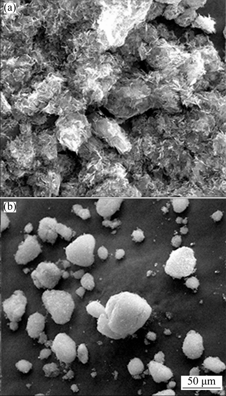
Fig. 1 SEM images of GNPs (a) and SiCp(b)
2 Experimental
Hot extruded AZ31 magnesium alloy plates (100 mm �� 100 mm �� 5 mm) were used for this experiments. SiCp with 40 nm in diameter (produced by Xuzhou Jiechuang New Material Technology Co., Ltd.) and GNPs with 15 nm in thickness (produced by Chengdu Organic Chemicals Co., Ltd., Chinese Academy of Sciences) were selected as the strengthening particles (as shown in Fig. 1). TiO2 with 120 nm in diameter was selected as activating flux. The SiCp/GNPs and TiO2 were mixed by acetone. Four groups of specimens were welded by ordinary TIG, A-TIG and NSA-TIG (two types of nano-particles were SiCp and GNPs) methods. During welding, the top surface of the welding specimens was coated by the hybrid coating. Unit areas (��A) of different specimens were calculated by the formula as follows:
 (1)
(1)
where m1 is the mass of plates before coating, m2 is the mass of plates after coating and S is the area of coating on the specimen. The ��A of specimens with pure TiO2 was (3.0��0.37) mg/cm2 with a width about 20 mm and ��A of specimens with TiO2+SiCp (GNPs) was (5��0.37) mg/cm2 with a width about 20 mm. The mass ratio of SiCp(GNPs)/TiO2 was 2:3 (Fig. 2). AC automatic welding machine (NSA-500-1) with an arc voltage controller (HAS-01-A) was applied for butt-welding tests, and pre-deformation was used in the experimental trials. The welding parameters were: welding current (80 A), arc distance (2 mm), welding speed (100 mm/min), and flow rate of shielding gas (7.5 L/min).
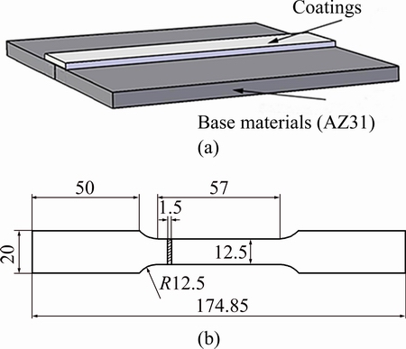
Fig. 2 Configuration for welding specimen (a) and tensile specimen (b)
After welding, the welded joints were photographed and the cross-sections of welded joints were prepared by standard metallographic procedures, including grinding, polishing and etching (2 g picric acid + 50 mL ethyl alcohol + 5 mL acetic acid). The microstructures of the welded joints were observed by an optical microscope (MDJ 200). An energy dispersive X-ray spectroscopy (Oxford, Inc., ISIS300, EDS) was used to detect the distribution of elements and phases formed in the welded joints. The penetrations and the widths of the weld bead were measured for the calculation of D/W ratios (D is the depth of specimen; W is the width of specimen). The microstructures of the welds were observed by a scanning electron microscope (TESCAN VEGA II LMV, SEM). Based on the quantitative stereology theory, the average grain sizes of the welded joints were collected.
As per the ASTM E8/E8M-13a, test specimens (Fig. 2(b)) were sectioned from the welded seams by a numerically controlled linear cutting machine to evaluate the ultimate tensile strength (UTS) of welded joints, respectively. The tensile tests were carried out by an electronic testing machine (SANS XYA105C) at room temperature with a rate of 1.5 mm/min and the tensile direction was perpendicular to the welded seams. Three tensile test results were collected on specimens with the same coating and the average value of them was adopted. Microhardness tests were performed by using a Vickers hardness tester (V-1000) with a load of 50 g and a load period of 20 s. The microhardness values were obtained from an average value of five data points. The phases were characterized by an X-ray diffractometer (XRD) (D/max 2500 PC, made by Rigaku Corporation, Japan) using Cu K�� radiation with a scanning angle from 10�� to 90�� and at a scanning rate of 4 (��)/min.
3 Results and discussion
3.1 Macromorphologies of welded joints
The outlines of the fusion zone (FZ) of the welded joints with/without different flux coatings are shown in Fig. 3, respectively. The effects of different coatings on the depth/width (D/W) ratio of the welded joints are shown in Table 1. From Fig. 3, the penetration in the cross-section of the welded joint without TiO2 coating (Fig. 3(a)) was about 1.5 mm. However, the penetrations with different flux coatings (Figs. 3(b)-(d)) all reached about 5 mm. Moreover, the penetrations and the D/W ratios of the welded joints increased gradually due to the addition of TiO2 flux coating. Besides, the values of D/W ratios of the weld joints with different strengthening particles are similar.
As demonstrated in previous study [15,16], the shape of the welded seam was determined by the change of the liquid flow in the weld pool. When TiO2 flux coating was adopted, the fluid flow of the molten pool surface transferred from the pool edge to the center easily, leading to the formation of narrow and deep welded seams (Figs. 3(b)-(d)). Although the strengthening particles are different, the mass values of TiO2 flux coating were similar. The values of D/W ratios and penetration of the welded joints with different strengthening particles were similar, which indicated that the addition of GNPs had minor influence on penetration.
3.2 Microstructures of welded joints
Figure 4 shows the typical microstructures of welded joints with/without TiO2+GNPs flux coating. The welded joint was composed of a FZ, a heat-affected zone (HAZ) and a base material (BM) area. The BM was characterized by a fine and uniform equiaxed structure. Due to the addition of TiO2, the width of HAZ of the welded joint with TiO2+GNPs flux coating was larger compared with that without flux coating.
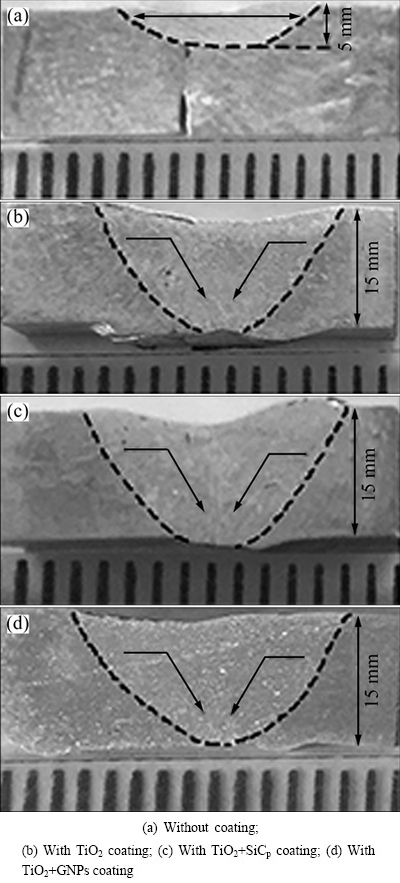
Fig. 3 Images of cross-sections of FZ of TIG welded joints with/without different strength particles
Table 1 Effects of different flux coatings on depth/width (D/W) ratio of welded joints
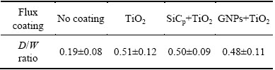
Figure 5 shows the second electron (SE) images of the FZ of the welded joint with TiO2+GNPs flux coating and the corresponding EDS results of the points. Figure 6 shows the XRD patterns of the FZ with/without different flux coatings. The microstructure of the FZ of the welded joint with TiO2+GNPs flux coating consisted of ��-Mg and secondary phases (Fig. 5(a)). According to EDS results, two kinds of phases distributed throughout the ��-Mg matrix. One is composed of Mg and C elements and the other is composed of Mg and Al elements. Based on the EDS results, XRD analysis results and the Mg-Al equilibrium phase diagram, it could be concluded that the secondary phases were GNPs particles (Point A in Fig. 5(a)) and intermetallic compound ��-Mg17Al12 particles (Point B in Fig. 5(a)). Since the sizes of second particles were quite small and the spatial resolution of electron probe was limited, the data of matrix and neighbor phases were included and reflected in spectrum peaks. Therefore, the composition deviation appeared in the phase analysis due to the excessively high content of matrix element (Mg).
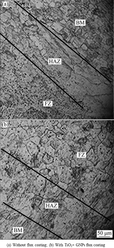
Fig. 4 Microstructures of welded joints with/without TiO2+ GNPs flux coating
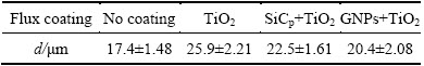
The average sizes of ��-Mg grains in FZ were collected and listed in Table 2. The sizes of the ��-Mg grains in the FZ of the welded joint with flux coatings were all larger than that of the welded joint without flux coating. However, among all the specimens with flux coatings, the finest ��-Mg grains formed in the FZ of the welded joint with TiO2+GNPs flux coating.
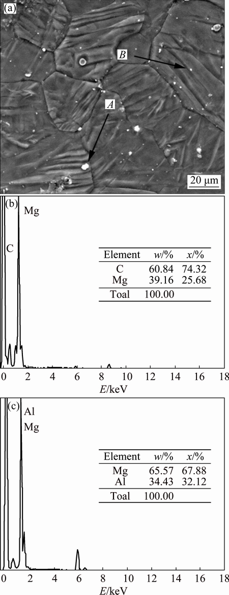
Fig. 5 Second electron (SE) image of FZ of welded joints with TiO2+GNPs flux coating (a) and corresponding EDS results of Points A (b) and B (c)
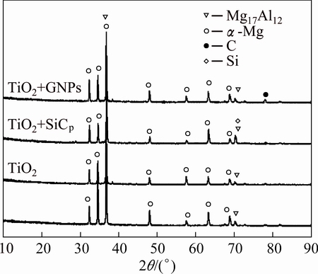
Fig. 6 XRD patterns of FZ of welded joints with/without different flux coatings
Table 2 Average grain size (d) of ��-Mg grains in FZ of welded joints with/without different flux coatings
The stable GNPs or SiCp in magnesium matrix played an important role in reducing the sizes of the ��-Mg grains, which can be explained by the following two factors [17-19]. 1) The GNPs/SiCp acted as nucleation agent to refine the grains in the FZ of magnesium alloy welded joints during solidification. 2) The GNPs/SiCp absorbed the energy from the matrix (��-Mg), which increased the cooling rate at the ��-Mg grain boundaries. So, the moving of the grain boundaries was hindered, which induced the grain refinement. According to the Zener limiting grain size principle, assuming a completely uniform distribution of clustering GNPs/SiCp, the Zener limiting grain size dZ can be calculated as follows [20]:
 (2)
(2)
where r is the radius of strengthening particles and Vf is the volume fraction of clustering strengthening particles, respectively. From Eq. (2), the smaller radius of strengthening particles resulted in the finer ��-Mg grains. Thus, the welded joint with TiO2+GNPs flux coating obtained the finer grains because of the smaller radius of GNPs. On the other hand, GNPs with high aspect ratio absorbed more energy from the matrix than that with SiCp, which induced that the welded joint with TiO2+GNPs flux coating obtained the finer grains. However, heat input caused by the flux coating of TiO2 has a stronger influence on the size of ��-Mg grains than that of strengthening particles. Thus, the finest ��-Mg grains were obtained in the welded joint without flux coating.
Element maps of the FZ of the weld joint with TiO2+GNPs flux coating are shown in Fig. 7. Figure 7 reveals that element C was uniformly dispersed in the matrix of the FZ. This result also proved that most of the added GNPs were almost uniformly dispersed in the matrix, which is beneficial to the improvement of mechanical properties of the AZ31 magnesium alloy welded joints.
3.3 Mechanical properties of welded joints
3.3.1 Microhardness of welded joints
Figure 8 shows the distribution of the microhardness of the TIG welded AZ31 magnesium alloy joint with TiO2+GNPs flux coating and the relationship between different flux coatings and the average microhardness of the FZ of the welded joints. From Fig. 8, the microhardness values of the BM and FZ are higher than that of the HAZ. What is more, the microhardness of the FZ of the welded joint decreased from HV 58.6 to HV 53.6 with the addition of TiO2 flux coating. The average microhardness of the FZ increased from HV 53.6 to HV 61.7 with the addition of TiO2+ GNPs flux coating and the microhardness of the FZ with TiO2+GNPs flux coating is higher than that of BM.
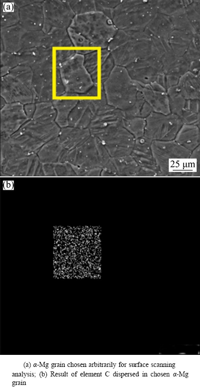
Fig. 7 Element maps of FZ of weld joint with TiO2+GNPs coating
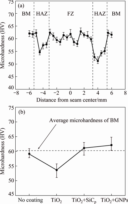
Fig. 8 Distribution of microhardness of TIG welded AZ31 magnesium alloy joint with TiO2+GNPs flux coating (a) and relationship between different flux coatings and average microhardness of FZ of welded joints (b)
The microhardness of the alloy is affected mainly by the grain size of primary-phase and the spacing between second-phase particles. The increase of TiO2 flux coating caused the increase in the heat input of welding pool. Hence, this led to the coarsening of the ��-Mg grains. According to Hall-Petch equation [21,22], a decrease in the grain size increased the microhardness of an alloy. However, Orowan hardening mechanism indicated that the decrease in the spacing between second-phase particles improved the hardness of an alloy [23]. In this study, the application of TiO2 flux coating led to serious coarsening of the ��-Mg grains in the FZ. The microhardness of the welded joint was mainly dominated by the Hall-Petch equation. While, the addition of TiO2+GNPs flux coating led to the refinement of ��-Mg grains and distributed the GNPs in the FZ (as seen in Table 2). Hence, the microhardness of the FZ was enhanced by both the Hall-Petch relationship and the Orowan hardening mechanism. Thus, the welded joints with TiO2+GNPs flux coating obtained the highest value in microhardness.
3.3.2 Tensile strength of welded joints
The relationship between different flux coatings and the ultimate tensile strength (UTS) of the TIG welded AZ31 magnesium alloy joints is depicted in Fig. 9. The tensile fracture specimen with TiO2+GNPs flux coating is shown in Fig. 10. From Fig. 9, the UTS value of the weld joints was increased by the addition of strengthening particles. Among all the AZ31 magnesium alloy welded joints, the UTS value of welded joint with TiO2+GNPs flux coating was the highest (198 MPa), which is similar to the value of the BM (204 MPa). Moreover, as shown in Fig. 10, necking occurred at the welded joint with TiO2+GNPs flux coating, which indicated that the ductility of the FZ increased sharply.
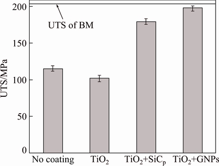
Fig. 9 Relationship between different coatings and UTS value of AZ31 magnesium alloy welded joints
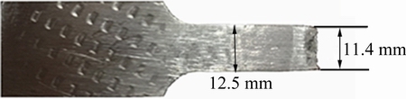
Fig. 10 Tensile fracture of welded joint with TiO2+GNPs coating
The UTS values of the weld joints increased from 178 to 198 MPa, in the case of the flux coating changed from TiO2+SiCp to TiO2+GNPs. This is caused by the effects of grain boundary strengthening (��gb), Orowan looping (��Orowan) , strengthening of ��CTE and load transfer (��LT) on the microstructure.
1) Grain boundary strengthening (��gb)
There is a clear trend in strength enhancement with the decrease of grain sizes, which is in agreement with the Hall�CPetch exponent that is listed as follows: [21,22].
 (3)
(3)
where ��gb is yield strength, �� is the parameter that describes the relative strengthening contributions of grain boundaries, and d is the size of ��-Mg grains (as shown in Table 2). From Table 2 and Eq. (3), the specimen with the TiO2+GNPs flux coating obtained a higher strength than the specimen with TiO2+SiCp flux coating.
2) Orowan looping (��Orowan)
Orowan looping also plays an very important role in increasing the strength value. Since nanoscale GNPs acted as obstacles restricted the movement of the dislocations [24], the dislocations face more obstacles during their motion, leading to the pile-up of dislocations. The Orowan strengthening could be described by the formula [25]
 (4)
(4)
where G is shear modulus, b is the magnitude of the Burgers vector, �� is the Poisson ratio, dt is the particles grain size and f is the volume fraction of the second particles. The grain size of the GNPs selected in this study is 15 nm and the SiCp is 40 nm. From Eq. (4), the sample with TiO2+GNPs flux coating obtained the higher strength.
3) Strengthening of ��CTE
Strengthening of ��CTE is induced by the difference about coefficient of thermal expansion (CTE) between particles and matrix, which could be described by the following formula [25]:
 (5)
(5)
where �� is a constant, b is the magnitude of Burgers vector, ��T is the difference between processing temperature and ambient temperature, dt is the particles grain size, and ��C is the difference of CTE of particles and matrix. The coefficients of thermal expansion for GNPs and SiCp are 1��10-6 K-1 and 4��10-6 K-1, respectively, while that for pure magnesium is only 2.5��10-7 K-1 [12,26]. From Eq. (5), the specimen with TiO2+GNPs flux coating obtained a higher strength than the specimen with TiO2+SiCp flux coating because of the larger difference of thermal expansion and smaller sizes.
4) Load transfer (��LT)
The strengthening ��LT was induced by the load transfer from the matrix to the particles. It could be expressed by the following formula [27]:
 (6)
(6)
where ��m is the yield stress of matrix, and m is the volume fraction of the second particles. From Eq. (6), the specimen with the TiO2+GNPs flux coating obtained a similar strength compared to the specimen with TiO2+SiCp flux coating. However, according to shear lag model [28,29], large aspect ratio could achieve a better reinforcement. Thus, the sample of GNPs with larger aspect ratio had higher strength.
At room temperature, the ductility of magnesium alloys strongly depends on the activation of basal slip systems, which has a much lower critical resolved shear stress than non-basal slip systems. Grain refinement has been considered as the most effective method to improve the ductility of polycrystalline magnesium alloy [30]. As shown in Table 2, the ��-Mg grains were obviously refined due to the flux coating of TiO2+GNPs. In addition, the microstructure of the FZ of the welded joint with TiO2+GNPs flux coating was more homogeneous. Thus, the ductility of the welded joint with TiO2+GNPs flux coating increased, which induced the necking.
SEM images of typical tensile fracture surfaces of the BM and the welded joints of AZ31 magnesium alloy with/without different flux coatings are shown in Fig. 11. All the fractures of the welded joints occurred in the FZ because the coarsening of ��-Mg grains. As shown in Figs. 11(a) and (e), the fracture surfaces of the BM and the welded joint with TiO2+GNPs flux coating mainly show the ductile fracture, which are characterized by more tearing fibers, ridges and dimples. The joint fracture surfaces without flux coating and with TiO2+SiC flux coating exhibited a character of a mixed fracture with obvious shear lips and dimples (Figs. 11(b) and (d)). The joint fracture surface with TiO2 flux coating mainly revealed a character of cleavage fracture belonging to a brittle fracture (Fig. 11(c)).
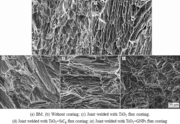
Fig. 11 Tensile fracture surfaces of BM and welded joints
4 Conclusions
1) Compared with the welded joint without flux coating, the penetration of the welded joint with TiO2 flux coating significantly increased. Moreover, the penetration of the welded joints with TiO2+GNPs flux coating and TiO2+SiCp flux coating was similar.
2) The FZ of the welded joints with TiO2+ GNPs/SiCp flux coating mainly consisted of ��-Mg grains, and ��-Mg17Al12 particles and the finest ��-Mg grains achieved in welded joints with TiO2+GNPs flux coating.
3) The UTS of the welded joints with TiO2+GNPs flux coating is about 198 MPa (similar to the value of the BM (204 MPa)) and the microhardness was determined to be HV 61.7 (larger than that of the BM (HV 60.5)) due to the effects of grain boundary strengthening, Orowan looping, strengthening of ��CTE and load transfer on the microstructure of FZ of the welded joints.
References
[1] LIU Zhi-yi, HUANG Tian-tian, LIU Wen-juan, KANG Sukbong. Dislocation mechanism for dynamic recrystallization in twin-roll casting Mg-5.51Zn-0.49Zr magnesium alloy during hot compression at different strain rates [J]. Transactions of Nonferrous Metals Society of China, 2016, 26: 378-389.
[2] WANG Qing-liang, XIONG Shou-mei. Vacuum assisted high- pressure die casting of AZ91D magnesium alloy at different slow shot speeds [J]. Transactions of Nonferrous Metals Society of China, 2014, 24: 3051-3059.
[3] ZHAO Chao-yong, PAN Fu-sheng, PAN Hu-cheng. Microstructures mechanical and bio-corrosion properties of as-extruded Mg-Sn-Ca alloys [J]. Transactions of Nonferrous Metals Society of China, 2016, 26: 1574-1582.
[4] SHEN Jun, WEN Li-biao, LI Yang, MIN Dong. Effects of welding speed on the microstructures and mechanical properties of laser welded AZ61 magnesium alloy joints [J]. Materials Science and Engineering A, 2013, 578: 303-309.
[5] LIU Li-ming, WANG Ji-feng, SONG Gang. Hybrid laser�CTIG welding, laser beam welding and gas tungsten arc welding of AZ31B magnesium alloy [J]. Materials Science and Engineering A, 2004, 38: 129-133.
[6] XU Jin-feng, QIU Ya. Microstructure and properties of TIG welding joint for AZ91B Mg alloy [J]. Special Casting & Nonferrous Alloys, 2004, 4: 1-10.
[7] XU Yan-li. Marangoni convection and weld shape variation in A-TIG welding process [J]. Theoretical and Applied Fracture Mechanics, 2007, 48: 178-186.
[8] DUNN G J, ALLEAND C D, EAGAR T W. Metal vapors in gas tungsten arcs. Part I: Spectroscopy and monochromatic photography [J]. Metallurgical and Materials Transactions A, 1986, 17: 1851-1863.
[9] SHEN Jun, ZHAI Da-jun, LIU Kai, CAO Zhong-ming. Effects of welding current on properties of A-TIG welded AZ31 magnesium alloy joints with TiO2 coating [J]. Transactions of Nonferrous Metals Society of China, 2014, 24: 2507-2515.
[10] LIU Li-ming. Mechanism and microstructure of oxide fluxes for gas tungsten arc welding of magnesium alloy [J]. Metallurgical and Materials Transactions A, 2007, 38: 649-658.
[11] SHEN Jun, LIU Kai, LI Yang, LI Shi-zheng, WEN Li-biao. Effects of fluxes on distribution of SiC particles and microstructures and mechanical properties of nanoparticles strengthening A-TIG (NSA-TIG) welded magnesium alloy joints [J]. Science and Technology of Welding and Joining, 2013, 18: 404-413.
[12] BALANDIN A A, GHOSH S S. Superior thermal conductivity of single-layer grapheme [J]. Nano Letters, 2008, 8: 902-907.
[13] WANG Jing-yue, LI Zhi-qiang, FAN Gen-lian, PAN Huan-huan, CHEN Zhi-xin, ZHANG Ding. Reinforcement with graphene nanosheets in aluminum matrix composites [J]. Scripta Materialia, 2012, 66: 594-597.
[14] RASHED M, PAN Fu-shen, TANG Ai-tao. Development of magnesium-graphene nanoplatelets composite [J]. Journal of Composite Materials, 2014, 1: 11-25.
[15] HEIPLE C R, ROPER J R. Effect of selenium on GTAW fusion zone geometry [J]. Welding Journal, 1981, 60: 143-145.
[16] HEIPLE C R, ROPER J R. Mechanism for minor element effect on GTA fusion zone geometry [J]. Welding Journal, 1982, 61: 97-102 .
[17] BRASZCYNSKA K N, LITYNSKA L A. TEM analysis of the interfaces between the components in magnesium matrix composites reinforced with SiC particles [J]. Materials Chemistry and Physics, 2003, 81: 326-328.
[18] ZHANG Shu-yan, JIANG Fu-song, DING Wen-bing. Microstructure and mechanical performance of pulsed current gas tungsten arc surface engineered composite coatings on Mg alloy reinforced by SiCp [J]. Materials Science and Engineering A, 2008, 490: 208-220.
[19] CAI Y, TAN M J, SHEN G J. Microstructure and heterogeneous nucleation phenomena in cast SiC particles reinforced magnesium composite [J]. Materials Science and Engineering A, 2000, 282: 232-239.
[20] MISHRA R S, MA Z Y. Friction stir welding and processing [J]. Materials Science and Engineering R, 2005, 50: 1-78.
[21] BOHLEN J, DOBRON P, SWIOSTEK J. On the influence of the grain size and solute content on the AE response of magnesium alloys tested in tension and compression [J]. Materials Science and Engineering A, 2007, 462: 302-306.
[22] HE S M, ZENG X Q, PENG L M, GAO X, NIE J F. Precipitation in a Mg-10Gd-3Y-0.4Zr (wt.%) alloy during isothermal ageing at 250 ��C [ J]. Journal of Alloys and Compounds, 2006, 421: 309-313.
[23] NIE Jian-feng. Effects of precipitate shape and orientation on dispersion strengthening in magnesium alloys [J]. Scripta Materialia, 2003, 48: 1009-1015.
[24] SZZBO B, BABUSKA I. Beams, plates and shells [M]. London: Wiley Online Library, 2011.
[25] AIKIN R, CHRISTODOULOU J L. The role of equiaxed particles on the yield stress of composites [J]. Scripta Materialia, 1991, 25: 9-14.
[26] LI Z, BRADT R. Thermal expansion of the cubic (3C) polytype of SiC [J]. Journal of Materials Science, 1986, 21: 4366-4368.
[27] CHEN W C, DAVIES C H, SAMARASEKERA I V. Mathematical modeling of the extrusion of 6061-A12O3 composite [J]. Metallurgical and Materials Transactions, 1996, 27: 4095-4103.
[28] CLYNE T W, WITHERS P J. An introduction to metal matrix composites [M]. Amsterdam: Elsevier, 1995.
[29] GAO X L, LI K. A shear-lag model for carbon nanotube-reinforced polymer composites [J]. International Journal of Solids and Structures, 2005, 42: 1649-1667.
[30] LAHAIR D, EMBURY J D. A note on the deformation of fine grained magnesium alloys [J]. Scripta Materialia, 1992, 27: 139-142.
�� �Σ��� ������·ǿ��������ɣ���£��� ��
�����ѧ ���Ͽ�ѧ�빤��ѧԺ ��е���������ص�ʵ���ң����� 400044
ժ Ҫ���о�ʯīϩƬ(GNPs)�����Ӷ�AZ31þ�Ͻ���������ǿ�����ټ�벻���(NSA-TIG)���ӽ�ͷ����֯����ѧ���ܵ�Ӱ�졣�������������Ի�����(A-TIG)��ȣ�NSA-TIG��ͷ�ۺ����Ħ�-Mg��������ϸ�����һ��Լ�ΪTiO2+GNPs�Ľ�ͷ�ں����Ħ�-Mg������С�����⣬��Ϳ��TiO2+SiCp ���Լ��Ľ�ͷ��ȣ�Ϳ��TiO2+GNPs���Լ���ͷ�����û�����Եı仯��������ѧ����(��Ӳ�Ⱥͼ�������ǿ��)��������ߡ���Ϳ��GNPs���ͷ������ʱ�����˾�������
�ؼ��ʣ�ʯīϩƬ����������ǿ�����ټ�벻�����AZ31þ�Ͻ�����֯����ѧ����
(Edited by Wei-ping CHEN)
Foundation item: Project (51375511) supported by the National Natural Science Foundation of China; Project (cstc2016jcyjA0167) supported by the Research Program of Basic Research and Frontier Technology of Chongqing of China; Project (SF201602) supported by the Science and Technology Project in the Field of Social Development of Shapingba District of Chongqing of China; Project (XJ201608) supported by the Key Industry Technology Innovation Funds of Science and Technology Development Board of Xiangcheng District of Suzhou of China
Corresponding author: Jun SHEN; Tel: +86-13883111150; E-mail: shenjun@cqu.edu.cn
DOI: 10.1016/S1003-6326(17)60149-3

