
J. Cent. South Univ. (2019) 26: 2961-2973
DOI: https://doi.org/10.1007/s11771-019-4228-y

Tribological and wear performance of centrifuge cast functional graded copper based composite at dry sliding conditions
N. RADHIKA, Manu SAM
Deptartment of Mechanical Engineering, Amrita School of Engineering, Coimbatore - 641112,Amrita Vishwa Vidyapeetham, India
 Central South University Press and Springer-Verlag GmbH Germany, part of Springer Nature 2019
Abstract: Non lubricated slide performance of functional grade copper matrix composite, fabricated using horizontal centrifuge cast technique was investigated using pin-on-disc tribo-tester. Rate of wear and friction coefficient of the inner wall thickness of hollow cylindrical cast specimen was analyzed using Taguchi based L27 orthogonal array, where the percentage of graphite particles were observed higher. Variable process parameters those influenced the rate of wear directly or indirectly were: applied load (15, 25 and 35 N), slide velocity (1.5, 2.5 and 3.5 m/s) and slide distance (750, 1500 and 2250 m). Rate of wear and friction coefficient showed a proportional dependency with applied load and slide distance, whereas showing a decline during intermediate slide velocity. Signal-to-Noise ratio predicted the minimal tribo-condition, on ��smaller-the-better�� basis. Analysis of Variance technique quantified the influence of affecting parameters, along with their interactions. Regression analysis was utilized for the validation of the experimental data. Micrographs and scanning electron microscopy exhibited the wear mechanisms and mechanically mixed layer formation during worn surfaces analysis.
Key words: functional graded materials; centrifuge casting; adhesive wear; Taguchi; tribology
Cite this article as: N. RADHIKA, Manu SAM. Tribological and wear performance of centrifuge cast functional graded copper based composite at dry sliding conditions [J]. Journal of Central South University, 2019, 26(11): 2961-2973. DOI: https://doi.org/10.1007/s11771-019-4228-y.
1 Introduction
Research of the past decade shows the growing demand for composites for applications like tribo-engineering mechanical components, sliding bearings, electrical bushes etc. Copper matrix is found feasible by certain researchers in the field of tribology with various liquid and solid state techniques like powder metallurgy, molding, casting etc [1, 2]. Copper reinforced with SiC by GANGWAR et al [3] showed optimum merge of Si with copper by 5%, providing improved strength. But the carbon formed as interfacial layer reduced the bonding strength. RALPH et al [4] observed that mechanical and tribological characteristics of base metal were enhanced when reinforced with carbides, metals or organic compounds, forming metal matrix composites (MMCs). As studied by HASHIM et al [5], among various manufacturing processes of MMCs, stir casting is considered most promising as it provides more simplicity, flexibility and applicability to large commercial productions of different industries [5]. Copper based composite provides a superior mechanical-tribo performance combination, making it more suitable for sliding contact applications. KENNEDY et al [6] suggest that enhanced anti-friction and anti-wear characteristics have become a necessity along with its superior thermo- electric conductivity. The wear performance of copper reinforced with 5wt% WC composite was subjected to sliding wear investigation by KATO [7] at dry conditions using pin-on-disc wear tester. This showed 38% improvement in wear performance under 10 N applied normal load. Addition of TiC (15 wt%) as a reinforcement to copper matrix produced by DESHPANDE et al [8] using microwave sintering, showed improved wear resistance during electrical sliding applications, as no interfacial de-bonding or cracks were observed under microstructural analysis. Graphite particle presence in MMCs led to continual transfer layer formations over the sliding counterpart. This had close dependency on the reduction of friction as studied by ROHATGI et al [9], under dry sliding conditions. Worn particles at the tribo-interface that causes abrasive effect are often trapped by the undulations induced by the surface texture, as observed by KOV
 IK et al [10]. Addition of a solid lubricant to a copper matrix induces low friction, reduced frictional temperature rise, anti-seizure functionality and improved wear performance. But DEVINCENT et al [11] found that graphite has low impact over its thermal and electrical properties. RIAHI et al [12] explored the utility of copper�Cgraphite particulate composites for applications like sliding constant load bearings, electrical brushes of electric motors etc., which work under dry sliding or non-lubricated environments. In another research, MOUSTAFA et al [13] observed that Cu-composites coated with 15 wt% and 20 wt% graphite showed minimum rate of wear withstanding higher loads up to 450 N and 500 N respectively, compared to those uncoated composites. ANOVA analysis on coefficient of friction (COF) of the copper matrix reinforced by graphite and tungsten disulfide particles showed 84% rise in rate of wear and 30% decline in COF, when the prime influential parameter load increased from 1 N to 5 N by CAO et al [14]. The presence of graphite at the tribo-interface produces a thin layer of graphite film over the counterface, GULTEKIN et al [15] observed reduce in COF as an effect. Poor interfacial strength observed at the pure copper- graphite interface by DAOUD et al [16], highlights the importance of alloying.
Based on the above literature, the wear performance and frictional impact of functional grade Cu-Ni-Si alloy, with graphite as reinforcement has not been researched effectively especially under dry sliding conditions. Hence an intensive experimental and analytical research has been performed with an intension to enhance those tribological properties, through effective integration of functionally graded materials (FGM) concept with centrifuge casting. Growing uitility and demand for particle reinforced copper FGMs in global market, specially for various tribo- applications like piston liners, electric bushes, machine bearings etc. [17] shows its importance in research.
2 Material selection
Copper possessing a high density (8.94 g/cm3) is a preferable matrix due to its exceptional physical as well as mechanical properties. Properties like better castability, optimum stiffness, improved thermal properties and electrical conductivity, desirable ductility, fracture resisting capacity, etc. make copper the best suitable as a matrix. Nickel was added to the base matrix during casting to improve the tensile strength, corrosion resistivity as well as thermal stability. Similar results were obtained by MOHANDAS et al [18], whereas silicon improves the wettability, machinability and tribo-properties of pure copper. Graphite particles being a solid lubricant were selected as reinforcement, to enhance the tribology performance and frictional behaviour of the copper composite. Copper matrix was initially alloyed with nickel (11 wt%), silicon (4 wt%) and further reinforced with Gr particles (10 wt%) using stir casting route. Excellent ceramic-metal bonding in composite was observed as key performance impactor by DINAHARAN et al [19] when produced through liquid metallurgy technique. The graphite particles were observed (Figure 1) in flake structure partially overlapped with adjacent crystals, during scanning electron microscopy (SEM) analysis. This facilitates better occupation of the interstitial voids and a sliding action which provides low friction apart from strengthening the composite.
3 Synthesis and microstructure analysis of functionally graded copper based composite
This functional graded copper composite was fabricated through stirring casting route, using horizontal centrifuge casting. Among the liquid state methods used for composite material synthesis, stirring casting is considered the most effectively implemented technique where the ceramic particles acts as a well distributed phase within the molten matrix. Mechanical stirring was performed with controlled operating parameters like stirrer speed and working temperature which in turn ensured better distribution. At first, 85% of copper was melt in a crucible (graphite made) kept within an electric furnace (Figure 2(a)) of chamber with dimensions of 300 mm��300 mm��250 mm. The inner chamber was designed to withstand a peak temperature of 1440 ��C and a stirrer rotation was set within a range of 0-800 r/min. Nickel (11 wt %) and silicon (4 wt%) were mixed for alloying the copper molten melt, which was used to prepare the base alloy. Melting process was progressed in an inert argon atmosphere to prevent undesirable chemical reactions, where gas was released to the chamber at a rate of 2-3 L/min. This molten metal (alloy) was stirred at a stirrer speed of 150 r/min powered by a 0.25hp motor.
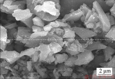
Figure 1 Reinforcement particles observed during SEM analysis
The flow pattern of the molten metal was highly influenced by the stirring speed, thereby creating a vortex. The flow pattern from inward to outward facilitated a uniform gradient distribution throughout. Graphite (10 wt%) particles were preheated to 200 ��C before introducing into the vortex to improve its thermal wetting properties. The stirring time was optimized to 10 min for better mixing of the reinforcements within the matrix. A 4500 W power rated oven was used to pre-heat the mould (Figure 2(b)). Thermal boundary formation was prevented by pre-heating the die (350 ��C). Later, the melt (1060 ��C) in the furnace was poured into a centrifuge mould (rotational velocity of 900 r/min) for solidification to finally produce a casting with dimensions of dout100 mm��din85 mm��100 mm (Figure 2(c)). Centrifuge force and density gradation were utilized in combination during centrifugal casting of this copper FGM, where the larger percentage of less dense and wear resistant additive particles moved towards the inner zone.
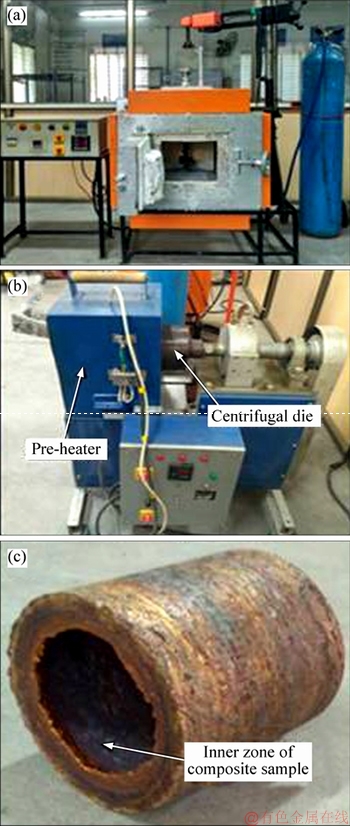
Figure 2 Furnace of melting copper (a), machine for centrifuge die casting (b) and cast sample of the composite (c)
Particle-rich inner composite specimen was undergone microstructure analysis using Zeiss made inverted microscope. Less dense graphite particles segregated more towards this region during centrifugal casting. The experimental specimen pins were prepared to physical dimensions of 20 mm��15 mm��10 mm. The fine polisher machine was used for specimen preparation and cutting damage removal. Mechanical polishing using emery papers (1/0, 2/0, 3/0 grits) ensured debris removal over the testing surface. Before etchant application, velvet/mirror polishing (with fine grade alumina powder) and diamond polishing enhanced the degree of reflectivity under microscope. Dilute acid was used as an etchant for selectively revealing the features. Nitric acid was proportionally diluted with distilled water during etchant preparation. The microstructure analysis performed at the inner periphery with an optimum magnification of 500x showed (Figure 3) higher concentration of well distributed reinforcement particles (light phase) over the copper matrix (dark phase).
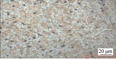
Figure 3 Microstructure observed at inner periphery
4 Adhesive wear test
Rectangular specimens with dimensions of 12 mm��12 mm��15 mm were used for dry sliding wear tests. Specimens from the inner wall of the composite were milled in such a way that the square faced (12��12) pins were in effective contact with the sliding surface. Experimental pin height was increased using stainless steel pipes of 35 mm length fixed over the specimen counter-face through cold setting. Tester was ASTM-G99 based using a pin-on-disc tribology tester (Figure 4). Track diameter (90 mm) was maintained unchanged for all the experiment trials. Each trial was performed by sliding the pin over stainless steel to make rotating disc of 8 mm disc thickness. The rotational velocity for the disc was fixed within 200-2000 r/min. The load limit was maintained at a range of 5-200 N. The disc sliding surface had a surface roughness of 0-2000 ��m. The hardened steel which acts as a counter face, was cleaned before each cycle using emery papers (1/0, 2/0 grit size) to ensure proper interfacial contact. The parameters for these experiments were applied load within a range of 15 to 35 N and in splits of 10 N, slide distance in range of 750 to 2250 m and in splits of 750 m and slide velocity within range 1.5 to 3.5 m/s in splits of 1 m/s. Experimented sample was made burr-free before each weigh trial. The mass reduction of each specimen after each trial was recorded for comparison. Wear rate was later calculated out of it. Cyclic stress induced at interfacial material surfaces leads to a phenomenon of adhesive wear. Similar inference was obtained by TJONG et al [20]. COF was also measured using the in-built function of DUCOM software, during each cyclic experiment.
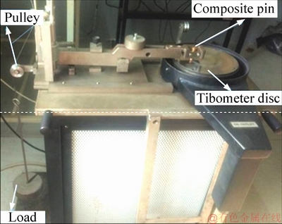
Figure 4 Pin-on-disc tester
5 Results and discussions
5.1 Tribological performance of developed composite
As higher percentage of less dense graphite particles (reinforcement) was observed at the inner wall of the composite, using microstructural analysis, the dry sliding wear test was experimentally designed for this zone. The experimentally obtained data can be validated and compared with a statistic approach named as design of experiment (DOE). Taguchi based DOE sorts the information based on priority, with the minimal experimental trials. With the orthogonal array (OA) experiment design, the investigator researches the impact of each influential factor over the average performance in an optimal way. Parametric interactional effects on wear rates are also estimated. Influence factors like applied load, slide distance and slide velocity were considered for the analysis.
The tribo-performance of the inner composite specimens was prioritized during adhesive tribo-test as this zone exhibited superior mechanical strength. The wear experiment results and its signal-to-noise (S/N) ratios are listed in Table 1.
5.2 S/N ratio analysis
The optimal parametric combination gives the least rate of wear (Table 2) and friction coefficient (Table 3), which was obtained through S/N analysis. This combination was detrimental through the comparison of supreme delta values obtained from the difference in values between upper and lower S/N ratios for each affecting factor. In the case of rate of wear, the impact of applied load was found with the most influence, then followed with slide distance and velocity. Whereas for COF, slide velocity becomes the second most influential parameter, followed by slide distance. Applied load remains most influential for both rate of wear and COF. Optimal parametric combination for both rate of wear (Figure 5(a)) and COF (Figure 5(b)), was found to be 15 N, 750 m and 2.5 m/s observed from the S/N plot.
5.3 Parametric impact on rate of wear
Graphical trends of each influential parameter (applied load, slide distance and slide velocity), are represented in Figures 6 and 7.
5.4 Applied load influencing tribo-performance
Rate of wear and COF were observed to increase proportionally when the applied load was increased from 15 N to 35 N as observed from Figures 6(a) and 7(a). Mild rate of wear was observed (Figure 6(a)) under low load (15 N) application as the sub-surface work hardening phenomenon was observed to resist deformation. Deformation due to plasticity observed on the material surface was insignificant as it varied directly with the both temperature and pressure over the slide surface when the applied load hike is up to 35 N. With the induction of supreme temperature and spiking pressure, considerable deformation due to plasticity was observed over the test surface. This promoted the adherence of pin surface scrap material onto the sliding stainless steel disc. Simultaneously, decline of COF occurred at low load (15 N) condition was observed in Figure 7(a).
Table 1 Tribology results and S/N ratios
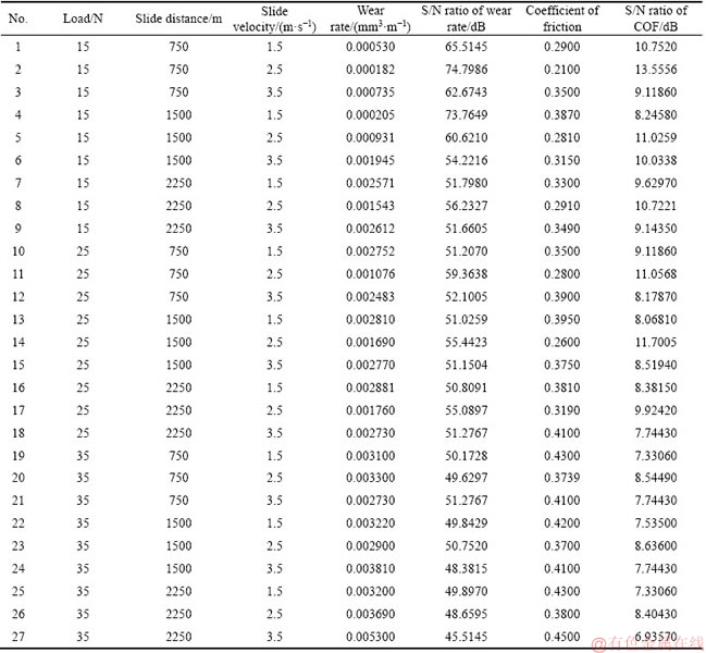
Table 2 Wear response ranking using S/N ratios
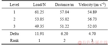
Table 3 COF response using S/N ratios
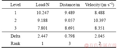
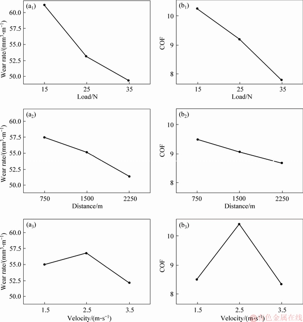
Figure 5 S/N ratio vs wear rate plot (a) and S/N ratio vs COF plot (b)
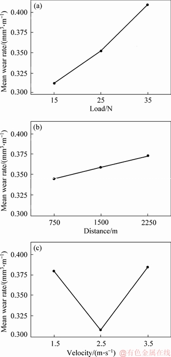
Figure 6 Mean wear rate plot
Whereas, the adherence occurring at high load condition (35 N) removed extra material through ploughing and delamination. This promoted the transition of wear from normal to severe; similar observation was mentioned by UTHAYAKUMAR et al [21]. The increase in plastic deformation over contact surface increased the apparent interfacial contact patch.The flake structured graphite particles were found partially overlapped, providing reduced spacing between the particles, also leading to 31% improvement in wear performance at 4 MPa. Similar partial overlapping of graphite flakes was also observed by ZHANG et al [22]. Therefore, the reinforcement particles acted as a solid lubricant which significantly reduced the COF at the particle-matrix interface under all experimental conditions.
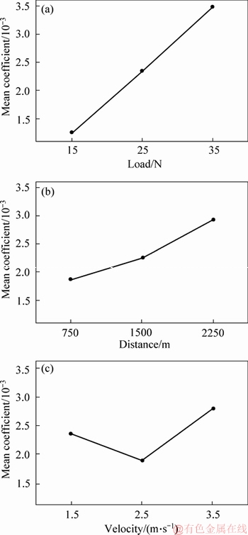
Figure 7 Mean coefficient of friction plot
5.5 Slide velocity influencing tribo-performance
The impact of slide velocity over the response of rate of wear and COF (Figures 6(c) and 7(c)) showed an initial decrease followed by a proportional increase after a critical velocity (2.5 m/s). This was due to the tribo-oxide layer formation called mechanically mixed layer-MML at 2.5 m/s. Copper often shows a tendency to form oxides. Mixture of debris produced from the micro-cutting phenomenon, when oxidized under optimum pressure and temperature, forms a compact layer, possessing contributions from both sliding surfaces. At low slide velocity (1.5 m/s), the interfacial heat raised due to frictional over-heat; promoting material surface oxidation. With the velocity rising (1.5 m/s to 2.5 m/s), this tribolayer restricts or lubricates the interface, declining the rate of wear. Similar observation was made by ZHANG et al [23] with SiC(61%)/Cu composite where tribolayer has contributed 70% reduction in wear rate at intermediate velocities. At high velocity (3.5 m/s), this adhered layer or accumulated patch gets scrapped off, revealing the adjacent particles over the sliding interface. This led to increase in COF, which thereby increased the wear rate, showing features like delamination.
5.6 Slide distance influencing tribo-performance
Rate of wear and COF were observed proportionally increasing with increment in distance of sliding, as observed in Figures 6(b) and 7(b). During shorter distance (750 m), the hard reinforcement which acts as pointed asperity brings a phenomenon of dispersion hardening over the sliding surface. Bonding at the matrix- reinforcement interface was observed to be improved, as observed by GUL et al [24]. A linear rise was observed (Figure 6(b)) in the rate of wear when distance increased from 750 m to 2250 m. This was because the cyclic stress led to a periodic increase in rate of wear as well as COF (Figure 7(b)). This fatigue stress, induced during longer sliding distance (2250 m) and repeated cycles negatively affected the matrix-reinforcement bonding, leading to an unpattern disintegration of reinforcement particles which were embedded in the matrix. This further increased the rate of wear along the longer slide distance. This excellent bond strength provided by the presence of reinforcements at the inner periphery delayed the wear transition.
5.7 ANOVA-analysis of variance
The factors significantly influencing the wear performance and wear coefficient characteristics were statistically analyzed using ANOVA technique and interactive effects are displayed in Tables 4 and 5.
ANOVA results reveal the effects of influencing process parameters and the effect of their interactions, which has direct impact on the wear performance of any material. It was conducted utilizing a generalized linear model, where the rate of wear forms the response influential factor.
Table 4 Analysis of variance of tribo-response
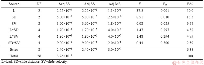
Table 5 Analysis of variance of coefficient of friction response
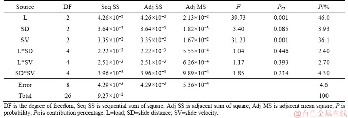
Significance level of 95% and 5% confidence limit were set for conducting the analysis. The significance of all the parameters was examined by ��Pct�� value and it is less than 0.05, showing extreme contribution over the rate of wear. From Table 4, the contribution percentage of each factor towards the rate of wear infers that applied load (59%) was the most influential on wear, followed by slide distance (13.3%) and slide velocity (9.57%). Table 5 depicts the contribution percentage of each factor towards the wear inferring that load (46%) was the most impacting factor over COF, followed by slide velocity (36.1%) and slide distance (3.93%). Also the interaction analysis of influential factors depicts that the interaction of applied load with slide velocity showed dominancy (4.79%) for wear rate but for COF, interaction of sliding distance and sliding velocity showed dominancy (4.30%).
5.8 Optical microscopy analysis on worn surface
Composite wear was analyzed under a variety of slide conditions using metallurgical microscope (Figure 8). At a combination of 15 N with 1500 m and 2.5 m/s kept constant, the worn surface showed (Figure 8(a)) tender scratches. When the applied load was increased (up to 35 N) accompanying unchanged slide velocity and slide distance, groove formation is observed (Figure 8(b)) indicating features of extreme wear. With 1.5 m/s at unchanged 1500 m and 25 N combination, the specimen surface (Figure 8(c)), exhibited wear debris formation due to ploughing phenomenon, resulting in severe wear. During intermediate sliding speed of 2.5 m/s, clustered oxidized worn particles were observed (Figure 8(d)), forming a thin unstable layer over the contact sliding surface. At peak slide speed of 3.5 m/s (Figure 8(e)), the composite exhibited non-uniform scrapings over the oxide layer, exposing the matrix layer for more wear and debris formation. This represents the wear transition from meagre to severe. Shallow wear tracks and minor delamination were observed (Figure 8(f)) to be scrapped towards the sliding direction at 750 m, 15 N and 1.5 m/s combination maintained unchanged. This produced least material scrappage. However, the sliding surface of the specimen at longer distance (2250 m) showed deeper wear tracks and surface weakening interfacial plasticity (Figure 8(g)). This was induced due to intensive shearing strain imposed over surface leading to severe wear.
5.9 Scanning electron microscopy analysis
For the better and detailed interpretations of the wear impact during wear test analysis at varied dry slide conditions, SEM (Figure 9) was preferred as an effective tool.
Rate of wear was observed (Figure 9(a)) the minimum at low load (15 N) due to non-uniform contact between the sliding mates at the interface at low pressure, resulting in a minimal wear. The shear induction was insufficient to retrieve the graphite particles from the copper base matrix which provided high interfacial strength. Rate of wear for the composite was highly impacted and controlled by the graphite particles, which caused cracks along the matrix due to plastic deformation at high load (35 N). Nature of high adhesive wear rate was observed (Figure 9(b)), leading to direct removal of material from specimen due to phenomena like severe deformation through plasticity and ploughing phenomena. Similar transition from meagre to intense wear was reflected at a load of 30 N on another research done by MANU [25], whereas the copper hybrid composite reinforced with Gr and TiC was subjected to dry sliding.
The influence of varied velocities (1.5, 2.5, 3.5 m/s) with unchanged slide distance (1500 m) and applied load (25 N) is depicted in Figures 9(c), (d) and (e), respectively. At 1.5 m/s, composite surface showed (Figure 9(c)) intense wear features like strain zones and micro cuts towards the slid direction. Low radius pits and scratches were resulted out of prolonged interfacial scrub of composite specimen and sliding counter face at low velocity. Weakened bond strength at the matrix- reinforcement interface, under high fatigue stress has led to the pull-out of reinforcements. With these features, it is interpreted that abrasive wear is the dominating tribological phenomenon at low slide velocity (1.5 m/s) and thus produced intense rate of wear. The specimen worn at intermediate velocity (2.5 m/s) revealed (Figure 9(d)) features of shallow scrubs with wider pits or grooves producing low intense wear with low COF. This was also due to the occurrence of a tribolayer (MML), which contributed more towards the minimal rate of wear. A similar inference was reported by BHATIJA et al [26]. At higher velocity (3.5 m/s) of slide, under unchanged slide distance and applied load, features like flake formations were observed (Figure 9(e)) along the worn surface. These features have led to broad ploughing phenomenon, indicating severe wear. This was due to the scrap-off of tribolayer at extreme velocity.
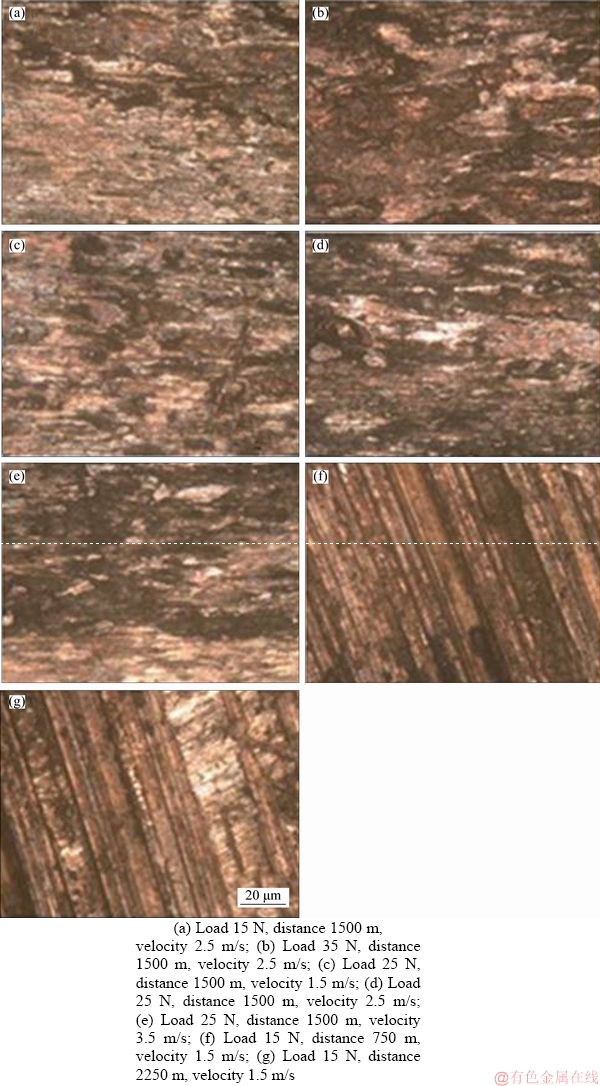
Figure 8 Metallurgy microscopy images of specimen surfaces worn at varied sliding conditions:
Influence of slide distances (750 and 2250 m) on the rate of composite wear with unchanged load (15 N) and velocity of sliding (1.5 m/s) is observed through Figures 8(f) and (g), respectively. It is observed (Figure 9(f)) that at shorter distance(750 m), minor scratches were observed towards the slid direction. The composite exhibited a minimal rate of wear due to the larger percentage of equi-axed soft ceramic particles (graphite) over the worn surface. The rise in rate of wear was plotted (Figure 9(g)) as the slide distance raised to 2250 m. This is due to the formation of tribo debris, which formed the third body to penetrate to the superficial matrix after scrapping the graphite film during its action of sliding. As the reinforcements resisted the penetration, it impacted phenomena like gouging and reinforcement pull-outs. This resulted in intense wear.
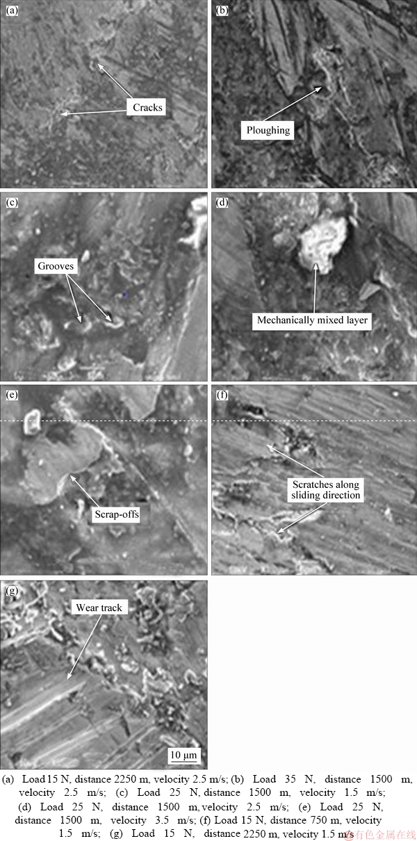
Figure 9 Worn specimen SEM analysis at varied slide conditions:
Composite specimen worn under optimum condition (15 N, 750 m and 2.5 m/s) exhibited (Figure 10) minimum wear tracks, narrow scratches and pits or grooves. At this parametric combination, the composite exhibited a minimal wear.
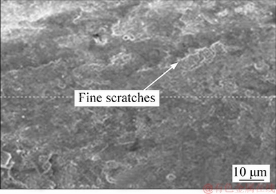
Figure 10 Optimal worn specimen surface
6 Conclusions
A centrifuge cast functional graded Cu-11Ni-4Si/10wt%Gr composite material was efficiently developed. The tribological investigation performed over the developed copper composite, under dry slide conditions revealed that both rate of wear and COF were directly affected by applied load and slide distance. With slide velocity, initial decline and further rise were observed. A statistical approach of Taguchi based DOE concluded load as the most affecting factor for both rate of wear (59%) and COF (46%). For the best wear performance, S/N ratio plots and ANOVA highlighted the optimum experimental factorial conditions as low load (15 N) applied along with moderate slide velocity (2.5 m/s) and low slide distance (750 m). The SEM performed over the worn surfaces along with their respective micrographs exhibited effective transition from minimal to normal wear and then to intensive wear. This observation was effective to spiking applied load and slide distance. It also revealed MML formation, as an induced wear mechanism at the intermediate velocities.
This investigation of tribological behaviour suggests that this composite can be effectively used for a variety of impactful applications like automotive components, especially engine cylinder inner lining and brake drum where tribo- performance at the inner periphery has the major importance.
References
[1] KOMPOZITOV T I, SUHEM P. The friction and wear behavior of Cu-Ni3Al composites by dry sliding [J]. Materials and Technology, 2011, 45(5): 401-406.
[2] MANU S, RADHIKA N. Effect of heat treatment on mechanical and tribological properties of centrifugally cast functionally graded Cu/Al2O3 composite [J]. Journal of Tribology, 2018, 140(2): 021606.
[3] GANGWAR S, BHAT I K, PATNAIK A. Tribological and microstructure examination of environmental waste (marble dust) filled silicon bronze alloy for wear resistant applications [J]. Silicon, 2017, 9(2): 249-263.
[4] RALPH B, YUEN H C, LEE W B. The processing of metal matrix composites��An overview [J]. Journal of Materials Processing Technology, 1997, 63(1-3): 339-353.
[5] HASHIM J, LOONEY L, HASHMI M S. Metal matrix composites: Production by the stir casting method [J]. Journal of Materials Processing Technology, 1999, 92: 1-7.
[6] KENNEDY F E, BALBAHADUR A C, LASHMORE D S. The friction and wear of Cu-based silicon carbide particulate metal matrix composites for brake applications [J]. Wear, 1997, 203: 715-721.
[7] KATO H, TAKAMA M, IWAI Y, WASHIDA K, SASAKI Y. Wear and mechanical properties of sintered copper�Ctin composites containing graphite or molybdenum disulfide [J]. Wear, 2003, 255(1-6): 573-578.
[8] DESHPANDE P K, LIN R Y. Wear resistance of WC particle reinforced copper matrix composites and the effect of porosity [J]. Materials Science and Engineering A, 2006, 418(1, 2): 137-145.
[9] ROHATGI P K, RAY S, LIU Y. Tribological properties of metal matrix-graphite particle composites [J]. International Materials Reviews, 1992, 37(1): 129-152.
[10] KOVIK J, EMMER  , BIELEK J. Effect of composition on friction coefficient of Cu�Cgraphite composites [J]. Wear, 2008, 265(3, 4): 417-421.
[11] DEVINCENT S M, MICHAL G M. Reaction layer formation at the graphite/copper-chromium alloy interface [J]. Metallurgical Transactions A, 1993, 24(1): 53-60.
[12] RIAHI A R, ALPAS A T. The role of tribo-layers on the sliding wear behavior of graphitic aluminum matrix composites [J]. Wear, 2001, 251(2): 1396-1407.
[13] MOUSTAFA S F, EL-BADRY S A, SANAD A M, KIEBACK B. Friction and wear of copper�Cgraphite composites made with Cu-coated and uncoated graphite powders [J]. Wear, 2002, 253(7, 8): 699-710.
[14] CAO H, QIAN Z, ZHANG L, XIAO J, ZHOU K. Tribological behavior of Cu matrix composites containing graphite and tungsten disulphide [J]. Tribology Transactions, 2014, 57(6): 1037-1043.
[15] GULTEKIN D, UYSAL M, ASLAN S, ALAF M, GULER M O, AKBULUT H. The effects of applied load on the coefficient of friction in Cu-MMC brake pad/Al-SiCp MMC brake disc system [J]. Wear, 2010, 270(1, 2): 73-82.
[16] DAOUD A, EL-KHAIR M A. Wear and friction behavior of sand cast brake rotor made of A359-20 vol% SiC particle composites sliding against automobile friction material [J]. Tribology International, 2010, 43(3): 544-553.
[17] UNLU B S, ATIK E. Evaluation of effect of alloy elements in copper based CuSn10 and CuZn30 bearings on tribological and mechanical properties [J]. Journal of Alloys and Compounds, 2010, 489(1): 262-268.
[18] MOHANDAS A, RADHIKA N. Studies on mechanical behaviour of aluminium/nickel coated silicon carbide reinforced functionally graded composite [J]. Tribology in Industry, 2017, 39(2): 145-151.
[19] DINAHARAN I, SATHISKUMAR R, MURUGAN N. Effect of ceramic particulate type on microstructure and properties of copper matrix composites synthesized by friction stir processing [J]. Journal of Materials Research and Technology, 2016, 5(4): 302-316.
[20] TJONG S C, LAU K C. Tribological behaviour of SiC particle-reinforced copper matrix composites [J]. Materials Letters, 2000, 43(5, 6): 274-280.
[21] UTHAYAKUMAR M, ARAVINDAN S, RAJKUMAR K. Wear performance of Al�CSiC�CB4C hybrid composites under dry sliding conditions [J]. Materials & Design, 2013, 47: 456-464.
[22] ZHANG G, SCHLARB A K. Morphologies of the wear debris of polyetheretherketone produced under dry sliding conditions: Correlation with wear mechanisms [J]. Wear, 2009, 266(7, 8): 745-752.
[23] ZHANG L, HE X B, QU X H, DUAN B H, LU X, QIN M L. Dry sliding wear properties of high volume fraction SiCp/Cu composites produced by pressure-less infiltration [J]. Wear, 2008, 265(11, 12): 1848-1856.
[24] GUL F, ACILAR M. Effect of the reinforcement volume fraction on the dry sliding wear behaviour of Al�C10Si/SiCp composites produced by vacuum infiltration technique [J]. Composites Science and Technology, 2004, 64(13, 14): 1959-1970.
[25] MANU S, RADHIKA N. Development of functionally graded Cu-Sn-Ni/Al2O3 composite for bearing applications and investigation of its mechanical and wear behaviour [J]. Particulate Science and Technology, 2018, 1: 1-12.
[26] BHATIJA K A, RADHIKA N. Studies on sliding wear characteristics of aluminium LM25/silicon dioxide functionally graded composite and optimisation of parameters using response surface methodology [J]. Materialwissenschaft und Werkstofftechnik, 2017, 48(6): 600-610.
(Edited by YANG Hua)
���ĵ���
�����ݶ�ͭ�����ϲ��ϵ��Ʊ�����Ħ��ĥ������
ժҪ������ˮƽ�������칤�գ��Ʊ������ݶ�ͭ�����ϲ��ϣ���������������ܽ������о������û���Taguchi��L27����ʵ���ʯī���������ϸߵĿ���Բ�������ڱں�ȵ�ĥ�����ʺ�Ħ��ϵ�����з�����ֱ�ӻ���Ӱ��ĥ�����ʵĹ��ղ���������ʩ�ӵ��غ�(15��25��35 N)�������ٶ�(1.5��2.5��3.5 m/s)�ͻ�������(750��1500��2250 m)��ĥ�����ʺ�Ħ��ϵ����ʩ�ӵ��غɺͻ�������ʱ����������ԣ������м们���ٶ��ڼ���ֳ��½���������ڡ���С-�Ϻá��Ļ�����Ԥ����С���������������������������Ӱ�켰������á����ûع������ʵ�����ݽ�����֤����ĥ�������������У�ͨ��������ɨ�������������ĥ����ƺͻ�е��ϲ���γɡ�
�ؼ��ʣ������ݶȲ��ϣ��������죻ճ��ĥ��Taguchi��Ħ��ѧ
Foundation item: Project(ERIP/ER/1503188/M/01/1587) supported by the Financial and Technological Support from Defense Research and Development Organization-DRDO, India
Received date: 2018-03-22; Accepted date: 2019-06-17
Corresponding author: N. RADHIKA, PhD; Tel: +91-9443566174; E-mail: n_radhika1@cb.amrita.edu; ORCID: 0000-0001-5138-2318

