
Compressive formability of 7075 aluminum alloy rings under
hydrostatic pressure
LIU Gang(�� ��), WANG Li-liang(������), YUAN Shi-jian(Է����), WANG Zhong-ren(������)
School of Materials Science and Engineering, Harbin Institute of Technology, Harbin 150001, China
Received 6 January 2006; accepted 18 July 2006
Abstract: In order to investigate the influence of hydrostatic pressure on compression limit of the ring, numerical simulation and experimental research were carried out. The effect of hydrostatic pressure on the deformation of aluminum alloy 7075 ring was obtained by numerical simulation. The die set for compressing ring under high hydrostatic pressure was designed and manufactured. Experimental results show that the compression limit increases linearly as the hydrostatic pressure increases in a certain range. At 100 MPa the maximum compressive strain is increased by 32.42%. At strain limit, the cracks initiate from the corner of the outer wall to the middle of the inner wall along the direction of the maximum shear stress.
Key words: ring sample; compression; hydrostatic pressure; formability; 7075 aluminum alloy
1 Introduction
In order to meet the demand of light-mass structure for aerospace and automobile industry, many new kinds of light alloys and composites are emerging day by day. But most of the high-strength alloys and the metal matrix composites used in the aerospace and automobile manufacturing industry are of low ductility and difficult to form at room temperature[1-3]. The formability of low plasticity material can be increased under the high hydrostatic pressure[4], and this was firstly confirmed by the famous K��rm��n experiment, in which the marble can be compressed by 8%-9%[5]. The hydrostatic compression experiment for samples of AlZnMgCu1.5 from room temperature to 250 �� under the hydrostatic pressure between 0 and 60 MPa was carried out by the researchers of the University of Hanover. The experimental results showed that at room temperature conventional forming results in a maximum achievable strain of about ��=0.5, but under the pressure of 60MPa, the maximum strain of ��=1.4 is realized[6]. Researchers concluded that hydrostatic pressure could increase the material plasticity, so the technologies such as the hydrostatic extrusion have been developed[7-9].
The compression experiments of NiAl polycrystals at room temperature under atmospheric press as well as 0.4 GPa were carried out. The stress��strain curves showed that the strength as well as the work-hardening rate was remarkably high when the sample was deformed under hydrostatic pressure[10]. The cold extrusion experiments showed that during the extrusion process, the hydrostatic pressure of the forming zone was increased by employing a counter pressure. It was possible to avoid the generation of cracks during and after the extrusion process by increasing the hydrostatic pressure. By this method, the ductility of these materials was increased, and the plastic deformation of the workpieces was more homogeneous. The magnitude of counter pressure to be applied to the extruded nose part of the workpiece can be predicted by the theory of plasticity. In this method, the mean stress transferred to the compression direction which increased the formability[11,12].
Ring components play an important role in the manufacturing industry, meanwhile ring compression experiment is an important method for investigating material deformation features and boundary conditions [13]. The compression research of ring components under high pressure may provide a new way for manufacturing ring components of low-ductility and high-strength. Numerical simulation and experimental research on compressing low-ductility material rings under hydrostatic pressure were carried out in this paper.
The main factors for the forming behavior and the forming limit were observed and analyzed by means of experimental research and numerical simulation, to determine the formability of low-ductility material under the hydrostatic pressure and the influence of hydrostatic pressure on forming, so that a theoretical basis for the cold forming of low-ductility materials was provided.
2 Numerical simulation
Numerical simulation was carried out to investigate the influence of hydrostatic pressure on the deformation of specimens using the finite element software DEFORMT M-2D. In the simulation, the upper and lower dies are assumed as rigid bodies; and the ring sample is assumed as rigid-plastic strain hardening material, whose stress��strain curve is shown in Fig.1. The ring sample is meshed by quadrilateral elements and the temperature is set as 20 �� without considering the temperature change during deformation. The movement of the upper die is 1 mm/s. Simulation scheme is shown in Table 1.
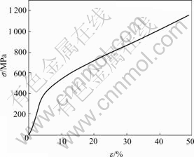
Fig.1 Stress��strain curve of 7075 aluminum alloy
Table 1 Numerical simulation scheme
Ring contour has significant effects on the compressive deformation, so the shape factor �� is proposed:
��=2H/(D-d) (1)
where H, D and d are the original height, outer diameter and inner diameter, respectively. The parameter �� indicates the ratio of specimen height to wall thickness.
2.1 Influence of hydrostatic pressure acted on inner wall
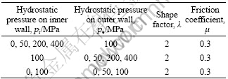
As the pressure acted on the outer surface is 100 MPa, the numerical simulation results under different inner pressures between 0 and 400 MPa are shown in Fig.2. With increasing pi, the metal flow and contour of the specimen change remarkably. When pi=0 and 50 MPa, the metal at the corner of inner wall flows inward because of the friction. When pi =200 MPa, all the metal flows outward homogeneously. As pi increases to 400 MPa, the deformation of the ring is not only compression but also bulging, and wall thickness decreases obviously.
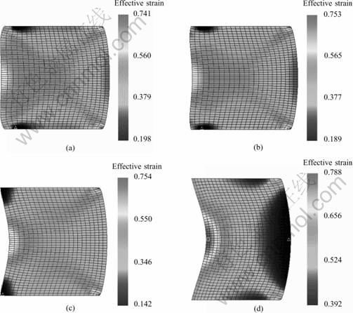
Fig.2 Influence of pi (pe=100 MPa, compression of specimen: 33%): (a) pi=0 MPa; (b) pi=50 MPa; (c) pi=200 MPa; (d) pi=400 MPa
2.2 Influence of hydrostatic pressure acted on outer wall
As the pressure acted on the inner surface is 100 MPa, the numerical simulation results under different outer pressures between 0 and 400 MPa are shown in Fig.3. As the pressure superimposed on the outer wall (pe) increases, the bulging of outer wall decreases obviously, which indicates that the superimposed pressure makes the metal flow inward. When pe=200 MPa, the inner wall begins to bulge. With pe increasing, hydrostatic pressure changes the direction of metal flow completely, and severe deformation area transfers from the corner of outer wall to the corner of inner wall.
Fig.3 Influence of pe (pi=100 MPa, compression of specimen: 33%): (a) pe=0 MPa; (b) pe=50 MPa; (c) pe=200 MPa; (d) pe=400 MPa
2.3 Influence of hydrostatic pressure acted on both sides on stress distribution
Homogeneous hydrostatic pressure superimposed on the specimen will change the mean stress into compressive stress, so the formability of materials will be increased. When compressing the ring specimens without hydrostatic pressure, radial and tangential stress near the outer wall is tensile stress which may cause the surface cracks. When the hydrostatic pressure is superimposed, the tensile stress decreases greatly, and the stress state will be changed to compressive one completely if the hydrostatic pressure is high enough. As shown in Fig.4 and Fig.5, the area enclosed by contour line is subjected to tensile stress. When the hydrostatic pressure is superimposed on both sides of the specimen, the tensile stress area decreases greatly or even disappears, which means the tensile stress is replaced by compressive stress.
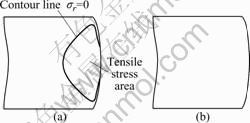
Fig.4 Radial stress distribution: (a) 0 MPa; (b) 100 MPa
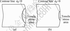
Fig.5 Tangential stress distribution: (a) 0 MPa; (b) 100 MPa
3 Die set and equipment for experiment
Schematic drawing of the compression die set with two ��Y�� type polyurethane sealing rings is shown in Fig.6. The high pressure in container is provided by a power unit. A bolster with grooves and a central hole is employed at the bottom of container to obtain the same pressure on both the inner and outer wall of the specimen.
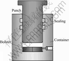
Fig.6 Schematic drawing of die set for hydrostatic compression
Experiments were carried out on a 1000 kN materials testing machine. Feeding motion of the punch was provided by the upward movement of worktable, and return motion was driven by the oil pressure in the container.
4 Specimen preparation
Quenched aluminum alloy specimens were employ- ed in the experiment. The yield strength was investigated by compression test. The yield strength and the compressive strength is 390 MPa and 560 MPa respectively. The specimen height is 15 mm, 22.5 mm and 30 mm, and the inner diameter and outer diameter are 15 mm and 30 mm respectively.
5 Hydrostatic compression experiment
Compressive ductility can be judged by the relative reduction before the generation of the first crack. But for a given material, relative reduction at the time of cracking depends on not only the temperature and velocity, but also the degree of deformation homogeneity. So for the given materials under given temperature and velocity conditions, different specimen sizes and the friction conditions can make different experiment results.
For the purpose of revealing the influence of hydrostatic pressure on compressing rings, experiments are carried out under constant deformation rate, deformation temperature and friction condition, by only changing the shape factor and hydrostatic pressure.
5.1 Hydrostatic compression processing
Compressed specimens (��=2) under different hydrostatic pressures are shown in Fig.7. The convex inner wall indicates that the friction makes the metal flow inward. Circular cracks can be seen with naked eyes along the middle of the inner wall. Specimens with different shape factor compressed under different hydrostatic pressures are shown in Fig.8 and Fig.9. With increasing shape factor, the bulging of the outer wall is more severe and the concave of the inner wall is more obvious, which is quite different from the case of ��=2. The cracks generate and expand before the maximum deformation is reached, so no overlap appears on the inner wall. Circular cracks can be seen with naked eyes along the middle of inner wall.
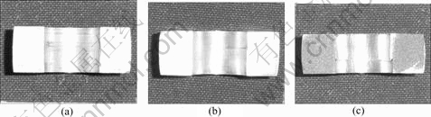
Fig.7 Specimens (��=2) compressed under different hydrostatic pressures: (a) 0 MPa; (b) 70 MPa; (c) 100 MPa
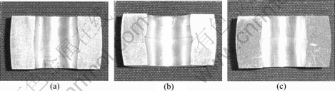
Fig.8 Specimens (��=3) compressed under different hydrostatic pressures: (a) 0 MPa; (b) 70 MPa; (c) 100 MPa
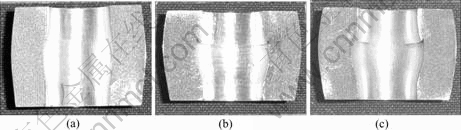
Fig.9 Specimens (��=4) compressed under different hydrostatic pressures: (a) 0 MPa; (b) 70 MPa; (c) 100 MPa
In order to investigate the generation and development of crack and the main factor for the cracks generation, low magnification photomicrographs are employed. Microstructure observation positions are shown in Fig.10. Section photomicrographs of the specimens (��=3) compressed without hydrostatic pressure during the middle and the last stage of fracture are shown in Fig.11 and Fig.12.
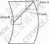
Fig.10 Schematic diagram of microstructure observation positions
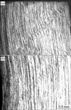
Fig.11 Photographs at middle stage of cracking: (a) Area A; (b) Area B
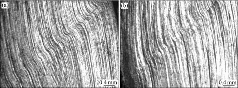
Fig.12 Photographs at last stage of cracking: (a) Area A; (b) Area B
A 1 mm-long crack can be seen at the corner of outer wall from Fig.11(a), and it becomes thinner at the front of the crack. No crack can be seen on the inner wall and flow lines are homogeneous as shown in Fig.11(b). Shear fracture of the ring takes place along the direction of maximum shear stress, and cracks on the inner wall can be seen with naked eyes as shown in Fig.12. It can be concluded from photomicrographs that cracks initiate from the corner of outer wall, and expand rapidly to the middle of inner wall along the direction of maximum shear stress.
In order to investigate the generation and development of the crack, 100 times magnified photomicrographs of crack at the three different stages are employed, as shown in Fig.13. It can be proved by the shear break of flow lines that generation of the cracks is caused by shear stress.
5.2 Experimental results
Hydrostatic pressure�Crelative reduction limit curves of the specimens (��=2, ��=3 and ��=4) are shown in Fig.14. And the relative reduction is
 (2)
(2)
where H0 and Hf are initial and final height of the ring.
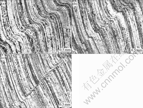
Fig.13 Microstructures at initial, intermediate and final stages of fracture: (a) Initial stage of fracture; (b) Intermediate stage of fracture; (c) Initial stage of fracture
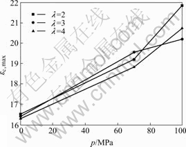
Fig.14 p����c,max curve of specimens with different shape factors
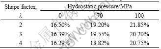
As hydrostatic pressure increases, the relative reduction limit of all the specimens linearly increases remarkably, which comes to an extension of the relative reduction limit of 32.42%, as shown in Table 2. It can be predicted from experimental data that with increasing hydrostatic pressure, the relative reduction limit will be further increased.
Table 2 Relative reduction limit under different pressures
6 Conclusions
1) Compression under different hydrostatic pressures superimposed on the inner surface, outer surface or both sides of the ring specimens is simulated by means of finite element method. The results illustrate that the hydrostatic pressure has a great effect on the metal flow and deformed contour due to notable change on stress state.
2) The forming limit of the 7075 aluminum rings increases linearly with adopting the hydrostatic pressure in a certain range. At 100 MPa, the maximum com- pressive strain is increased by 32.42%.
3) As the limit strain is reached, the cracks initiate from the corner of the ring outer wall and extend rapidly to the middle of the inner wall along the direction of the maximum shear stress.
References
[1] LAROSE J, LEWANDOWSKI J J. Pressure effects on flow and fracture of be-al alloys [J]. Metallurgical and Materials Transactions A, 2002, 33A: 3555-3564.
[2] AGNEW S R, DUYGULU ?. Plastic anisotropy and the role of non-basal slip in magnesium alloy AZ31B [J]. International Journal of Plasticity, 2005, 21: 1161-1193.
[3] SPITZIG W A, RICHMOND O. The effect of pressure on the flow stress of metals [J]. Acta Metall, 1984, 32(3): 457-463.
[4] LEWANDOWSKI J J, LOWHAPHANDU P. Effects of hydrostatic pressure on mechanical behaviour and deformation processing of materials [J]. Int Material Review, 1998, 43: 145-187.
[5] K?RM?N T V. Stiffenss measurement under hydrostatic pressure [J]. Journal of Association of German Engineering, 1911, 55: 1749- 1757. (in Germany)
[6] MEINERS F, R?HR S, SCHMIDT-JURGENSEN R. Extension of forming limits in forging of less ductile light weight metals by means of superimposed hydrostatic pressure [J]. Advanced Technology of Plasticity, 2002(1): 37-42.
[7] LAHAIE D J, EMBURY J D. Hydrostatic extrusion of metal matrix composites [J]. Journal of Composite Materials, 2003, 37(17): 1589-1599.
[8] LEWANDOWSKI J J, BERGER B, RIGNEY J D, PATANKAR S N. Effects of dislocation substructure on strength and toughness in polycrystalline NiAl processed via low-temperature hydrostatic extrusion [J]. Philosophical Magazine A, 1998, 78(3): 643-656.
[9] PATANKAR S N, GROW A L, MARGEVICIUS R W, LEWANDOWSKI J J. Hydrostatic extrusion of 2014 and 6061 composites [A]. Processing and Fabrication of Advanced Materials III [C]. The Minerals, Metals and Materials Society. Warrendale, PA, USA, 1993. 733�C743.
[10] SKROTZKI W, TAMM A R, OERTEL C G, BECKER B, BROKMEIER H G, RYBACKI E. Influence of texture and hydrostatic pressure on the room temperature compression of NiAl polycrystals [J]. Materials Science and Engineering, 2002, A329�C331: 235-240.
[11] WAGENER, HANS-WILFRIED, WOLF, JOACHIM, HAATS. Increase of workability of brittle materials by cold extrusion [J]. Journal of Materials Processing Technology, 1992(32): 451-460.
[12] HANS-WILFRIED W, HAATS W J. Increase of workability of MMCs by cold extrusion [A]. Proceedings of the International Conference on Advanced Composite Materials [C]. 1993, 1097-1103.
[13] ROBINSON T, OU H, ARMSTRONG C G. Study on ring compression test using physical modeling and FE simulation [J]. Journal of Materials Processing Technology, 2004, 153-154: 54-59.
Foundation item: Project(HIT.2002.33) supported by the Scientific Research Foundation of Harbin Institute of Technology
Corresponding author: LIU Gang; Tel: +86-451-86417917; Fax: +86-451-86417917; E-mail: gliu@hit.edu.cn
(Edited by YANG Bing)

