
New method of direct chill casting of Al-6Si-3Cu-Mg semisolid billet by annulus electromagnetic stirring
TANG Meng-ou(汤孟欧), XU Jun(徐 骏), ZHANG Zhi-feng(张志峰), BAI Yue-long(白月龙)
General Research Institute for Nonferrous Metals, Beijing 100088, China
Received 13 May 2010; accepted 20 June 2010
Abstract: The electromagnetic direct chill (EMDC) casting process is a well-established production route for aluminum alloy ingot, however, the skin effect restricts the casting diameter. In order to avoid this problem, annulus electromagnetic direct chill (A-EMDC) casting process has been developed. A three-dimension finite element computational model of A-EMDC casting process was established by using ANSYS Magnetic-Nodal programs and FLOTRAN CFD programs. Microstructures of A-EMDC casting semi-solid Al-6Si-3Cu-Mg alloy billets were investigated. Two pairs of vortexes occur within the crystallizer with opposite direction in A-EMDC. The annulus gap is advantageous to increasing circulate flow, reducing the temperature gradient as well as shallowing liquid sump depth. The microstructure obtained by A-EMDC is globular or rosette-like, and the microstructure is homogeneous in the billet.
Key words: electromagnetic stirring; semi-solid; continuous casting; Al-6Si-3Cu-Mg alloy
1 Introduction
The direct chill casting process has been used almost exclusively to produce aluminum ingots during the past 60 years owing to the relative simplicity of the equipment and its ability to produce high quality ingots[1]. Presently, electromagnetic direct chill casting (EMDC) technology has been a main method for producing the semi-solid slurry or billets on a commercial scale due to its non-pollution, easy process control and continuous production[2]. However, it has some shortcomings, for example, stirring force exerted in the slurry is larger in the external part but smaller in the inner one of the slurry because of the skin effect, which leads to inhomogeneous microstructures. The casting, refining and electromagnetic process (CREM) introduced by VIVES at the end of the 1980s[3] mainly aimed at the refinement of microstructure and improvement of surface quality of ingots. In the process, the skin effect was still not solved, which has restricted the casting diameter. Other efforts on overcoming the drawbacks by applying coupled magnetic fields called electromagnetic vibration (EMV) were also developed[4]. The main problem was still the restriction of casting diameter due to the sharp reduction of electromagnetic forces. Another research by directly applying alternative current to the melt in the mold through the launder during electromagnetic continuous casting called AC+EMCC was conducted[5]. This method intended to enhance the strength of electromagnetic force by directly applying alternative current to the melt but it was difficult to operate.
In the present study, in order to avoid the effect of skin effect, by combining hot-top continuous casting technology and the annular electromagnetic stirring (A-EMS) process[6-9], an advanced semi-solid metal processing technology, namely, the annular electro- magnetic direct chill (A-EMDC) casting process has been developed. A three-dimensional finite element computational model of A-EMDC is also developed. The effects of annulus gap on electromagnetic field, flow field, temperature field and the microstructure are investigated.
2 Experimental
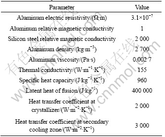
The alloy used in the experiment is Al-6Si-3Cu-Mg alloy, and its composition is listed in Table 1. Fig.1 shows DSC curve of the alloy. Its liquids temperature and the solids temperature are about 828.38 K and 898.37 K, respectively.
Table 1 Composition of alloy in this work (mass fraction, %)
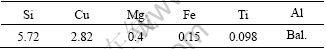
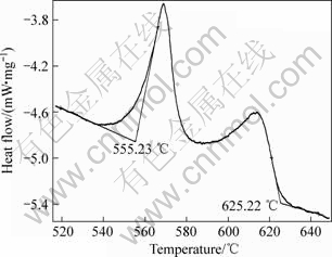
Fig.1 DSC curve of Al-6Si-3Cu-Mg alloy
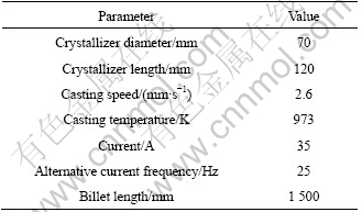
A schematic plot of the home-made A-EMDC apparatus is shown in Fig.2. In the apparatus, a centre pipe with closed bottom is set in the center of the hot-top. A narrow annulus gap between the hot-top and the center pipe is designed innovatively in order to weaken the skin effect and obtain the strong magnetic fields. The annulus gap width may be adjusted by changing the centre pipe. The room-temperature air is input to the inner centre pipe to make the temperature of the slurry uniform. The mold for casting is in cylindrical shape and made of aluminum. Inside the crystallizer, a graphite cylinder is embedded. An induction coil generating an alternating magnetic field in the melt is laid out around the crystallizer. During continuous casting, the aluminum melt was poured from the launder into the hot-top and then the billet was drawn continuously through the crystallizer by means of a dummy bar, which was controlled by a velocity controllable motor. The experimental parameters are listed in Table 2.The specimens cut from billet was observed with the Zeiss-type optical microscope after grinding, polishing and etching by 0.5% HF acid to investigate the microstructure.
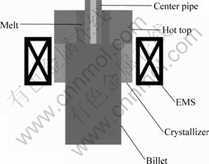
Fig.2 Schematic diagram of A-EMDC apparatus
Table 2 Experimental parameters
3 Model description
3.1 Basic assumptions
A series of complicated phenomena take place in the continuous casting process such as flow, heat transfer, solidification, solute segregation, and electromagnetic induction, in which flow and solidification are the basic phenomena. It is impossible to take all these phenomena into account in the model. By appropriately simplifying the model, the present study puts the emphasis upon the flow and heat transfer in mold cavity, especially on the thermal field. The assumptions in the model are given as follows[10-12]:
1) The aluminum flow in the mold is a steady-state, incompressible and viscosity flow process;
2) The taper of the mold walls is not taken into consideration;
3) All materials in the model are regarded as homogeneous phase medium;
4) Thermal insulation material and graphite are treated as air in electromagnetic model;
5) The time-averaged force substitutes for the time-varying force;
6) The additional magnetic field produced by the liquid aluminum flow in the mold is ignored.
3.2 Calculation method and simulation parameters
A three-dimensional finite element mathematical model of A-EMDC has been built based on the theory of computational fluid dynamics (CFD) and magneto- hydrodynamics (MHD), which is shown in Fig.3. Three-dimensional numerical simulation is studied by using the commercial software ANSYS. All the calculations are carried out by combining the ANSYS Emag programs and FLOTRAN CFD with a physics file-based load transfer. Simulation parameters are shown in Table 3.
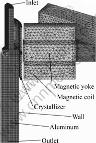
Fig.3 One sixth of model except air
Table 3 Simulation parameters
4 Results
4.1 Effect of annulus gap on induction electro- magnetic field
The induction electromagnetic field in the melt generated by the applied electromagnetic field would exert magnetic induction intensity and then result in electromagnetic force in the melt, as shown in Fig.4. Therefore, the electromagnetic force not only intensifies the melt exchange between the internal and the external of the sump due to the resulted agitation of vortex, which will reduce the radial temperature gradient of the billet, but also imposes scouring effect on the liquid/solid interface, which will be capable to break the primary dendritic grain validly[13-14].
Fig.5 shows the radial distributions of magnetic induction intensity at the bottom section of hot-top. It can be seen that there are similar distributions at different positions, i.e. the magnetic induction intensity, with the maximum near the billet surface, falls gradually toward the center. One can learn that the magnetic induction intensity is greater than 44 mT with A-EMDC; however, the minimum magnetic induction intensity is about 37 mT with EMDC. Therefore, the annulus gap avoids the occurrence of part of low magnetic induction intensity, consequently, A-EMDC avoids skin effect.
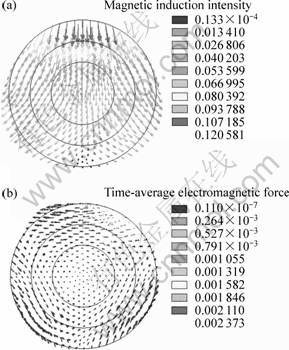
Fig.4 Distributions of induction electromagnetic field in melt (I=35 A, f=25 Hz): (a) Magnetic induction intensity (phase angle: zero); (b) Time-average electromagnetic force at XZ plane
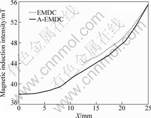
Fig.5 Radial distributions of magnetic induction intensity at bottom section of hot-top (I=35 A, f=25 Hz)
4.2 Effects of annulus gap on flow and temperature field
Fig.6 shows the comparison of the flow fields with and without annulus gap at a casting velocity of 2.6 mm/s with an AC frequency of 25 Hz and current of 35 A. With the applied annulus gap, the fluid flow pattern in Fig.6(a) changes largely owing to the forced convection affected by electromagnetic force. As a result, four vortexes occur within the crystallizer, which could reduce the temperature gradient effectively in virtue of liquid convection between the center and the skin areas. Two are located at the core of the crystallizer near the hot-top and the other two under the centre pipe. In Fig.6(b), the melt flows into the hot-top vertically by and large, and the flow is natural convection caused by the momentum of the liquid from the trough during casting. As a result, two vortexes occur at the core of the crystallizer near the hot-top, but they are less than those in Fig.6(a). From Fig.5, the distribution of magnetic induction intensity within the melt varies with the presence of annulus gap. Therefore, the situation of the forced flow caused by electromagnetic force would also be different, and the temperature field in the melt would change finally.
Fig.7 shows the comparison of the temperature fields with and without annulus gap at a casting velocity of 2.6 mm/s. It can be observed from Fig.7 that the isothermal lines of the liquidus temperature and solidus temperature in A-EMDC are more even than those in EMDC, and move somewhat upward. It is known that the density of the isothermal lines reflects the temperature gradient. It is obvious that the temperature gradient of the longitudinal direction in the solidification region decreases and the depth of liquid sump shallows evidently as shown in Fig.7(a). This means that there is a large mushy region in A-EMDC.
In the foregoing statement, the temperature field varies with the change of flow pattern. The axial flow in Fig.6(b) is not effective and quick enough to reject heat, and the melt with higher temperature would gather in the center part, so a deep liquid sump would present in the middle part of the billet, as shown in Fig.7(b). The circular flow in Fig.6(a) could reduce the temperature gradient effectively in virtue of liquid convection between the center and the skin areas, and then the depth of the liquid sump shallows evidently.
4.3 Influence of annulus gap on microstructure
Fig.8 shows the microstructures obtained by A-EMDC at a casting velocity of 2.6 mm/s with an AC frequency of 25 Hz and current of 35 A. The samples were cut in the centre of the billet at distance of 200 mm, 750 mm, and 1 300 mm from the dummy bar, respectively. The primary α(Al) particles are globular or rosette-like in the billet obtained by A-EMDC. From Fig.8, it can also be seen that the microstructures are uniform at different positions of the billet.
As shown in Fig.6(b) and Fig.7(b), the circular flow improves the melt exchange between the internal and external of the chamber due to the agitation of vortex, which will quickly lead to a relatively uniform temperature distribution in the slurry and reduce the temperature gradient. It is visible from Fig.6(b), Fig.7(b) and Fig.8 that the circular flow is more effective than the axis flow, and the larger mushy region in the crystallizer would result in uniform microstructure. It should be pointed out that the circular flow is also in favor of composition fields due to the scouring effect of the vortexes on the melt. Therefore, the melt in crystallizer is not only cooled down quickly because of a large and ever-renewing surface area at both the melt/crystallizer interface and melt/pipe interfere, but also reaches uniform composition field. As a result, nucleation will occur in the entire volume of the liquid and each nucleus will survive. Under this situation, the growth will be limited and stable, and ideal globular microstructures can be obtained[15].
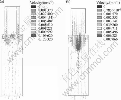
Fig.6 Flow fields at XY plane for different apparatus at casting velocity of 2.6 mm/s: (a) A-EMDC; (b) EMDC
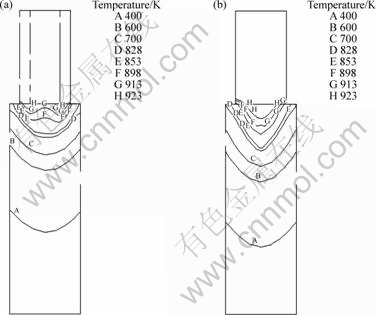
Fig.7 Temperature fields at XY plane for different apparatus at casting velocity of 2.6 mm/s: (a) A-EMDC; (b) EMDC
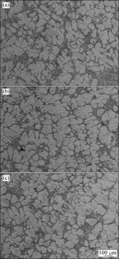
Fig.8 Microstructures of alloy at different distances from dummy bar obtained by A-EMDC at casting velocity of 2.6 mm/s: (a) 200 mm; (b) 750 mm; (c) 1 300 mm
5 Discussion
The improvement of microstructure is directly related to the electromagnetic stirring. In EMDC process, alternative magnetic field is generated by the alternative current in the inductor coil and then induction current occurs. An electromagnetic force owing to the induced electromagnetic field is produced in the melt and controls the grain growth and microstructure evolution. The characteristic length, which specifies how the magnitude of magnetic field decreases as a function of distance into the liquid metal, is the skin depth:
 (1)
(1)
where ρ and μ are the resistivity and permeability, respectively, of the liquid metal; f is the frequency. It is visible from Eq.(1) that the magnetic field induced by lower frequency AC has higher penetrability. But it also should be pointed out that the volume density of electromagnetic field energy ω includes that of electric field ωe and that of magnetic ωm[16]:

 (2)
(2)
where n is the turn number of the electric solenoid per unit height and I is the current intensity in the electric solenoid. It is visible from Eq.(1) and Eq.(2) that the magnetic induction intensity and the volume density of magnetic energy increase with the increase of the current intensity in the induction coil. The induction electric field intensity E is proportional to the change rate of magnetic flux  . The change rate will decrease within a sinusoidal wave period at the lower AC frequency, and then E will decrease as well. So ωe, and then ω, decreases at lower AC frequency according to Eq.(2). Therefore, although the low AC frequency is helpful to improving penetrating depth of electro- magnetic field in the melt, it results in decrease of total energy of electromagnetic field.
A new electromagnetic force is generated in the melt by applying an AC current, which is determined by inputting current intensity and the induced magnetic field:
F=J×B (3)
where J is the inputting AC current density and B is the induced magnetic flux density. The conduction of input AC current is also submitted to skin effect. Hence, the input AC current is not distributed homogeneously in the melt. At the same time, the induced magnetic flux density exerted in the slurry is small at the inner part. Therefore, the skin effect is still not solved. In the present case, the center pipe is innovatively designed to avoid the part of low magnetic induction intensity and increase the average stirring intensity. Thus, A-EMDC reduces the opposite influence of skin effect and the beneficial flow fields are obtained.
6 Conclusions
1) The characteristics of magnetic field, flow field and temperature field during A-EMDC were analyzed. The annulus gap avoids the part of low magnetic induction intensity, consequently, A-EMDC avoids skin effect.
2) Two pairs of vortexes occur within the crystallizer with opposite directions in A-EMDC. The annulus gap is advantageous to increasing circulate flow, reducing the temperature gradient and shallowing liquid sump depth.
3) The microstructure obtained by A-EMDC is globular or rosette-like, and homogeneous in the billet.
References
[1] VIVES C, RICOU R. Experimental study of continuous electromagnetic casting of aluminum alloy [J]. Metall Trans B, 1985, 16(2): 377-384.
[2] SPENCER D B, MEHRABIAN R, FLEMINGS M C. Rheological behavior of Sn-15%Pb in the crystallization range [J]. Metall Trans, 1972, 3(7): 1925-1932.
[3] VIVES C. Electromagnetic refining of aluminum alloys by the CREM process. Part I: Working principle and metallurgical results [J]. Metall Trans B, 1989, 20(5): 623-629.
[4] GUO S J, LE Q C, ZHAO Z H, WANG Z J, CUI J Z. Microstructural refinement of DC cast AZ80 Mg billets by low frequency electromagnetic vibration [J]. Mater Sci Eng A, 2005, 404(1/2): 323-329.
[5] YU J B, JIANG J M, REN Z M, YU J B, JIANG J M, REN Z M, REN W L, DENG K. A new method of continuous casting of copper billets by a combination of AC current and magnetic fields [J]. Mater Des, 2009, 30(10): 4665-4569.
[6] XU Jun, ZHANG Zhi-feng, BAI Yue-long, SHI Li-kai. The method and apparatus for preparing the semisolid rheo-slurry or billets. CN101618438A [P]. 2008-01-06. (in Chinese)
[7] BAI Y L, XU J, ZHANG Z F, SHI L K. Annulus electromagnetic stirring for preparing semisolid A357 aluminum alloy slurry [J]. Transactions of Nonferrous Metals Society of China, 2009, 19(5): 1104-1109.
[8] ZHU G L, XU J, ZHANG Z F, BAI Y L. Annular electromagnetic stirring―A new method for the production of semi-solid A357 aluminum alloy slurry [J]. Acta Metallurgica Sinica (English Letters), 2009, 22(6): 408-414.
[9] CHEN Xing-rung, ZHANG Zhi-feng, XU Jun, SHI Li-kai. Numerical simulation of electromagnetic field in semi-soli slurry preparation by A-EMS [J]. Journal of University of Science and Technology Beijing, 2009, 31(10): 1305-1310. (in Chinese)
[10] DUGNOL ALVAREZ B, FERNANDEZ MARTINEZ J L, GARZON MARTIN M L, CALLEJA QUINTANA J M. Mathematical modelling of the process of continuous casting of aluminium and its alloys [J]. Finite Elem Anal Des, 1999, 33(1): 43-59.
[11] YU Hai-qi, ZHU Miao-yong. 3D numerical simulation of flow field and temperature field in round billet continuous casting mold with electromagnetic stirring [J]. Acta Metall Sinica, 2008, 44(12): 1465-1473. (in Chinese)
[12] BESSON O, BOURGEOIS J, CHEVALIER P A, RAPPAZ J, TOUZANI R. Numerical modelling of electromagnetic casting processes [J]. J Comput Phys, 1991, 92(2): 482-507.
[13] MEYER J L, EL-KADDAH N, SZEKELY J, VIVES C, RICOU R. A comprehensive study of the induced current, the electromagnetic force field, and the velocity field in a complex electromagnetically driven flow system [J]. Metall Trans B, 1987, 18(3): 529-538.
[14] DOHERTY R D, LEE H J, FEEST E A. Microstructure of stir-cast metals [J]. Mater Sci Eng A, 1984, 65(1): 181-189.
[15] ESKIN D G, NADELLA R, KATGERMAN L. Effect of different grain structures on centerline macrosegregation during direct-chill casting [J]. Acta Materialia, 2008, 56(6): 1358-1365.
[16] JIA Qi-min, ZHENG Yong-ling, CHEN Ji-yao. Electromagnetics [M]. Beijing: Higher Education Press, 2001: 262. (in Chinese)
(Edited by YANG Bing)
Foundation item: Project(2009AA03Z534) supported by the National Hi-tech Research and Development Program of China; Project(2006CB605203) supported by the National Basic Research Program of China
Corresponding author: XU Jun; Tel: +86-10-82241221; E-mail: xujun@grinm.com
DOI: 10.1016/S1003-6326(09)60344-7

