Effects of sealing process on corrosion resistance and roughness of anodic films of titanium alloy Ti-10V-2Fe-3Al
来源期刊:中南大学学报(英文版)2011年第6期
论文作者:刘建华 吴量 于美 李松梅 吴国龙
文章页码:1795 - 1801
Key words:sealing; corrosion resistance; roughness; calcium acetate; titanium alloy
Abstract:
Anodic oxide films of titanium alloy Ti-10V-2Fe-3Al were sealed in calcium acetate solution. The morphology and composition of the sealed films were investigated using scanning electron microscopy (SEM), atomic force microscope (AFM) and energy dispersive spectroscopy (EDS). The results show that the sealing process makes the anodic oxide films more uniform. Elemental calcium is presented through the whole depth of the anodic oxide films. The roughness of the anodic oxide films is reduced after the sealing process. Electrochemical impedance spectroscopy (EIS) and potentiodynamic polarization were used to study the corrosion behavior of the anodic oxide films. It is revealed that the sealing process improves the corrosion resistance of the anodic oxide film of titanium alloy Ti-10V-2Fe-3Al.
J. Cent. South Univ. Technol. (2011) 18: 1795-1801
DOI: 10.1007/s11771-011-0904-2![]()
LIU Jian-hua(刘建华), WU Liang(吴量), YU Mei(于美), LI Song-mei(李松梅), WU Guo-long(吴国龙)
School of Materials Science and Engineering, Beihang University, Beijing 100191, China
? Central South University Press and Springer-Verlag Berlin Heidelberg 2011
Abstract: Anodic oxide films of titanium alloy Ti-10V-2Fe-3Al were sealed in calcium acetate solution. The morphology and composition of the sealed films were investigated using scanning electron microscopy (SEM), atomic force microscope (AFM) and energy dispersive spectroscopy (EDS). The results show that the sealing process makes the anodic oxide films more uniform. Elemental calcium is presented through the whole depth of the anodic oxide films. The roughness of the anodic oxide films is reduced after the sealing process. Electrochemical impedance spectroscopy (EIS) and potentiodynamic polarization were used to study the corrosion behavior of the anodic oxide films. It is revealed that the sealing process improves the corrosion resistance of the anodic oxide film of titanium alloy Ti-10V-2Fe-3Al.
Key words: sealing; corrosion resistance; roughness; calcium acetate; titanium alloy
1 Introduction
Titanium and its alloys are currently used as a kind of new material for aeronautic, chemical and biomedical applications due to the unique combination of high specific strength, melting temperature and corrosion resistance [1-3]. Anodic oxidation is a common and simple used surface treatment on titanium substrate to increase the thickness and corrosion resistance of the anodic oxide films. It is understood that the anodic oxide films formed on titanium in sulfuric acid, phosphoric acid, fluoride or ammonium tartrate electrolyte are of porous structure, consisting of very lager numbers of cells or cracks [4-6]. This is very similar to the anodic oxide films formed on aluminum [7-9]. The porous structure, with a high specific surface area, possesses the capability of absorbing water and aggressive substances from media [10]. Since the aggressive substances may penetrate into the very thin barrier layer, the porous films without further treatment cannot provide the desired corrosion resistance. Consequently, it is essential to close the micropores with sealing after anodizing [11].
Tremendous efforts have been contributed to understanding and developing numerous sealing processes for anodic oxide films of aluminum [11]. Acetate sealing was developed to provide an excellent sealing quality for anodic oxide films on aluminum alloys [12]. Elemental calcium has drawn many attentions because it could enhance the compatibility between body and titanium alloys [13]. Meanwhile, calcium acetate is one component of the solution which was used for anodizing of titanium alloys [14].
A novel anodic oxidizing process on Ti-10V-2Fe- 3Al titanium alloys in ammonium tartrate electrolyte was reported in Refs.[8, 15]. In this work, a sealing process to anodic oxide films of titanium alloys using aqueous solution of calcium acetate was studied. The effects of the method on the corrosion resistance and the surface roughness of the anodic oxide films were evaluated using EIS technique. The morphology, component and roughness of the sealed anodic oxide films were investigated by SEM, EDS and AFM, respectively.
2 Experimental
2.1 Materials
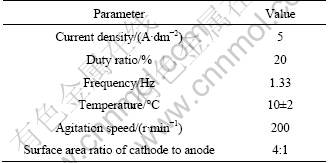
A Ti-10V-2Fe-3Al forged block was cut into 50 mm × 25 mm ×2 mm sheets and 10 mm × 10 mm × 3 mm sheets. The nominal components of Ti-10V-2Fe- 3Al alloy are shown in Table 1.
2.2 Preparation of anodic oxide films
The parameters of anodizing process are shown in Table 2 and the fabrication conditions were studied in detail previously in Ref.[8].
Table 1 Nominal components of Ti-10V-2Fe-3Al alloy (mass fraction, %)

Table 2 Parameters of anodizing processes
2.3 Sealing method of anodic oxide films
The sealing of anodic oxide films was undertaken in 10 g/L calcium acetate aqueous solution (85-90 °C, pH 6-7) for 15 min. The specimens sealed were rinsed with deionized water and finally dried in the air.
2.4 Films morphology and composition characteriza- tion
The surface and cross-section morphologies of the films were examined using scanning electron microscopy (SEM, JSM5800, JEOL, Japan). The composition and element distribution of cross-sections of the coated substrates were studied with energy dispersive spectroscopy (EDS, link ISIS, Oxford, England). Atomic force microscope (AFM, Nanoscope Ⅲa, Instruments Inc, USA) was used to observe the surface morphology of the anodized titanium samples in air by a tapping mode with MPP21100 type cantilever (Veeco Instruments, resonant frequency 70-90 kHz). The root-mean-square roughness (RMS) and average roughness (Ra) analysis were performed with the accompanying Nanoscope IIIa software. The roughness of anodic oxide films on titanium was also obtained by AFM.
2.5 Electrochemical impedance spectroscopy
The EIS spectra of the films were measured in a three-electrode cell (a pure platinum plate was used as counter electrode, a saturated calomel as reference electrode, and the coated sample with area of 1 cm2 as working electrode) through a potentiostat/galvanostat (Parstat 2273, Princeton Applied Research, USA) in a 3.5% NaCl solution at room temperature.
The EIS data were acquired over frequency region from 100 kHz to 10 mHz at 10 points per decade, with an AC voltage amplitude of 10 mV. Bode plots were obtained by fitting these data points using a commercial software package called Electrochemistry Power Suite TM. The measured EIS spectra of the films were fitted and interpreted by the Zsimpwin simulation software.
2.6 Potentiodynamic electrochemical measurement
Potentiodynamic polarization curves were generated in 3.5% NaCl solution at room temperature, using the same three-electrode cell as in Section 2.5. The potentiodynamic scanning speed was 5 mV/s, with a scanning ranging from -0.1 V of open circuit potential to +0.7 V of open circuit potential.
3 Results and discussion
3.1 Morphology and composition characterization
Figure 1 shows the micrographs of the surface and cross-section of the sealed and unsealed anodic oxide films. Numerous randomly-shaped cavities and cracks, with size from 1 to 10 μm, are evident on the surface before sealing (Fig.1(a)). Observation of the cross- section of the treated alloy reveals that the thickness of anodic oxide films is about 9.5 μm (Fig.1(b)). Images (Figs.1(c) and (d)) show different surface morphologies for the sealed anodic oxide films. The number of the randomly-shaped cavities and cracks is intensively reduced. The image shows a rather smooth morphology, which may be attributed to the result of sealing in calcium acetate solution (Fig.1(c)). Figure 1(d) reveals that the thickness of the anodic oxide films after sealing is about 10 μm. The sealed films are a little thicker than the unsealed ones.
The EDS depth profile recorded from most elements of the anodized layer after sealing reveals that elemental calcium exists in the films (Fig.2). The percentage of elemental calcium at the outer layer is about 10.5%, which decreases gradually to a background level over a thickness of approximately 5-10 μm. This indicates that elemental calcium penetrates into the depth of the films through the pores and cracks. Further, the calcium-rich regions are presented on the surface of films. The reactions during sealing may occur mostly in these regions. As the percentage of elemental calcium is similar to that of elemental carbon, the production may be calcium hydroxide and then change into calcium carbonate.
The AFM 3D topographic representations of the sealed and unsealed anodic oxide films are displayed in Fig.3. Figure 3(a) shows that the surface morphology of the unsealed anodic oxide films is rough. A lot of humps are found in the whole area. After sealing in calcium acetate solution, the surface of the anodic oxide films of titanium alloy shows smoother morphology compared with that of the unsealed samples (Fig.3(b)). Lots of particles, which may be the productions of the reactions between calcium acetate and water, are seen on the surface of anodic oxide films after sealing. Figure 4 shows the variation of root-mean-square roughness (RMS) and average roughness (Ra) obtained from the AFM analysis on the recorded images for different treatments. It is clear that the RMS and Ra values decrease after sealing.

Fig.1 SEM images of surface and cross-section of anodic oxide films on Ti-10V-2Fe-3Al titanium alloy: (a), (b) Unsealed film; (c), (d) Sealed film

Fig.2 EDS depth profile recorded for most elements of anodized layer after sealing
3.2 Mechanism of sealing process
The changes of film morphology and composition are related to the mechanism of sealing process. All these findings above can be summarized in a four-step mechanism (Fig.5) which is proposed as follows.
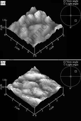
Fig.3 AFM 3D topographic representations of anodic oxide films of titanium alloy: (a) Unsealed film; (b) Sealed film
Step 1: Calcium ions in the solution react with water to produce the precipitation of calcium hydroxide (Eq.(1)). The loose sediments accumulate around hole mouths, where some small hole mouths are plugged directly and other big hole mouths become smaller. Meanwhile, titanium dioxide reacts with water and forms hydrated titanium dioxide (Eq.(2)). As the concentration of calcium ions is higher in the bulk solution, the reaction of calcium ions and water continues to produce precipitation of calcium hydroxide. This reaction is fast, and the reaction time for this step is short. The reaction between calcium ions and water is the main reaction.
Ca2++2H2O=Ca(OH)2↓+2H+ (1)
TiO2+H2O=TiO2・H2O (2)
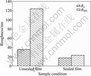
Fig.4 RMS and Ra values of anodic oxide films of titanium alloy
Step 2: The sealants (water molecules, calcium ions, etc.) go through the narrow channel into the depth of the hole, so the sealing reaction gradually takes place from outer side to inner side. But when the sealants permeate into the porous layer deeper, the resistance of diffusion will be higher. Water molecules react with titanium dioxide at the hole wall to form hydrated titanium dioxide. As the hole mouths are plugged, the migration rate of hydrogen ions is faster than the hydroxyl ions within the channel. So the pH value in the holes is lower, the reaction rate of precipitation of calcium hydroxide decreases. This step has longer reaction time and the reaction between water and titanium dioxide is the main reaction.
Step 3: Hydrated titanium dioxide and calcium hydroxide precipitation link with each other in the holes when the reactions proceed. The internal space of the hole is completely filled by the reaction products, while calcium hydroxide and hydrated titanium dioxide have a synergistic effect on enhancing the corrosion resistance of anodic oxide films.
Step 4: The hydrates convert into more stable forms. Aging occurs in the products of reaction. Hydrated titanium dioxide loses water (Eq.(3)), and calcium carbonate is produced from the reaction of calcium hydroxide and carbon dioxide (Eq.(4)).
TiO2・H2O=TiO2+H2O (3)
Ca(OH)2+CO2=CaCO3+H2O (4)

Fig.5 Schematic maps of proposed mechanism for sealing in calcium acetate salt solution: (a) Pore mouth plugging due to calcium hydroxide precipitation on surface; (b) Hydrated titanium dioxide forms on wall of hole; (c) Hydrated compounds plug holes; (d) Conversion of hydrates into more stable forms
3.3 Corrosion resistance of unsealed and sealed films
The polarization behavior of the sealed and unsealed anodic oxide films is presented in Fig.6. For the specimen supporting the unsealed anodic oxide films, corrosion current density is obtained in range from 10-5 to 10-6 A/cm2. The sealed anodic oxide films result in a significant reduction in corrosion current density to about 10-6-10-7A/cm2. Furthermore, the value of potential after sealing is obviously much higher than that before sealing.
Anodization leads to improve the corrosion resistance of titanium alloy [16]. Furthermore, sealing of anodic oxide films can shift the polarization curves to reduced current densities, with the extent depending on the particular sealing treatment. From the behavior illustrated in Fig.6, it is concluded that sealing in calcium acetate solution provides improved barrier protection subsequently.

Fig.6 Polarization potentiodynamic curves recorded in 3.5% NaCl solution for anodized Ti-10V-2Fe-3Al titanium alloy: (a) Unsealed film; (b) Sealed film
3.4 EIS analysis
Impedance spectra for sealed and unsealed anodic oxide films on Ti-10V-2Fe-3Al titanium alloy in 3.5% NaCl solution are represented as Bode plots and shown in Figs.7(a) and (b), respectively. Figure 7(a) exhibits a high impedance value at high and intermediate frequency for sealed anodic oxide films, compared with the unsealed anodic oxide films. HITZIG et al [17] proposed that |Z| Bode plot at intermediate frequency reflected the resistance of porous layers in anodic oxide films. As the sealing of anodic oxide films mostly happens in the porous layers, the resistance of porous layers can reflect the quality of sealing process. The higher the resistance of porous layers, the better the quality of sealing process will be [18]. So the |Z| Bode plots at intermediate in Fig.7(b) indicate that the sealed anodic oxide films gain better corrosion resistance of the porous layers compared with the unsealed anodic oxide films.
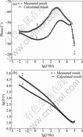
Fig.7 Phase angle (a) and impedance modulus (b) for anodic oxide films of titanium alloy: 1―Unsealed film; 2―Sealed film
From Fig.7(a), it can be seen that the phase angle observed at low frequency for unsealed anodic oxide films is nearly -40°. However, at intermediate frequency, the phase angle shifts to -50°, and decreases to -45° at high frequency. All of these indicate that the unsealed anodic oxide films exhibit two distinct capacitive behaviors. For the sealed anodic oxide films, the figure of Bode plots is similar to that of the unsealed anodic oxide films. Besides, the phase angle is much higher than that of the unsealed anodic oxide films in the intermediate frequency region, indicating an increase in corrosion resistance of the anodic oxide films [19].
Using EIS fitting software (Zsimpwin simulation software) to fit and interpret the measured EIS, the EIS spectra fitted with the model Rs(Q1(RtQ2)) [20-21] are shown in Fig.8. The Chi-squared is within 10-4 during the fitting process. The impedance fitting values are shown in Table 3. This is a modified Randles circuit, which is composed of two parts, the former is the solution resistance (Rs), the latter is a parallel connection circuit, which consists of Q1 and series Rt and Q2, where Q1 is the constant-phase element (CPE) of the outer layer, Rt is the electric charge transfer resistance and Q2 is the constant-phase element of the inner layer of the films. Here, Q and n are the magnitude and the exponent of the constant-phase element, respectively, described by an empirical impedance function. The impedance of the constant-phase element is defined in Eq.(5) [22]:
![]() (5)
(5)
where the constant Q is the magnitude of CPE; n is the empirical exponent of the CPE, 0≤n≤1. If n=1, Q is the pure capacitance; if n=0, Q is the pure resistance.
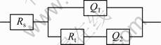
Fig.8 Equivalent circuit of anodic oxide films on Ti-10V-2Fe- 3Al alloy in 3.5% NaCl solution: Rs―Solution resistance; Q1― CPE of outer layer of films; Q2―CPE of inner layer of films; Rt―Electric transfer resistance
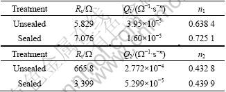
Table 3 Impedance fitting values of films under different treatments
The electrochemical impedances for sealed and unsealed anodic oxide films on Ti-10V-2Fe-3Al titanium alloy are given by
 (6)
(6)
ZCPE in Eq.(5) is inserted to Eq.(6), and the electrochemical impedances of the titanium alloys are calculated and shown as
 (7)
(7)
According to Eq.(7), the impedances of the sealed and unsealed anodic oxide films increase with the increase of the resistance (Rs and Rt) and the decrease of the constant-phase element (Q1, Q2). From Table 3, it can be seen that the impedance of the sealed anodic oxide films is higher compared with that of the unsealed anodic oxide films.
Here, Q1 is the CPE of the outer layer, reflecting the dielectric behavior of the electrolyte/films interface. A true capacitive behavior has a value of n=1, and is rarely obtained [23]. Q1 becomes C for n=1. As C=C0A, where C0 and A are normalized capacitance and the exposed films area, respectively. The decrease of Q1 shows that A becomes small, which is consistent with the changing of the film morphology in Fig.1.
The value of n1 is associated with the non-uniform distribution of current as a result of roughness and surface defects [22]. In addition, the empirical exponent of the constant-phase elements is related to the fracture dimension (DF) of the coarse surface [20-21]. The changing of n1 is mainly due to the roughness of the surface of the material, and DF is a physical variable corresponding to the roughness. The decrease of the roughness results in the decrease of the fracture dimension (DF) and increase of the value of n1. Furthermore, the relation between n and DF is shown as follows [20-21]:
![]() (8)
(8)
It is observed that the n1 value of the sealed anodic oxide films is higher than that of the unsealed anodic oxide films. Therefore, the value of DF decreases after sealing process, which demonstrates that the sealing in calcium acetate solution reduces the roughness of the films. These above results well explain the changing of the surface morphology of the films in Fig.1 in further.
The charge transfer not only happens at the interface between the solution and the films, but also in the whole film layer, so the value of Rt can reflect the difficulty of the charges transferring the films and the compactness of the films [23]. Table 3 also shows that Rt of the sealed anodic oxide films (3 399 W・cm2) is about five times larger than that of the unsealed anodic oxide films (665.8 W・cm2). The value of Rt of the sealed anodic oxide films increases intensively, which shows that the compactness of the films also improves due to the sealing process.
Furthermore, the corrosion resistance of the coated samples can also be assessed through Rt because it is conversely proportion to the corrosion current, whether the electrode process is reversible or not. The higher the Rt is, the better the corrosion resistance of the coated sample is. Therefore, the value of Rt of sealed anodic oxide films is much higher than that of the unsealed anodic oxide films, which indicates that sealing process can improve the corrosion resistance of the coated sample. Therefore, EIS results are in agreement with the previous potentiodynamic polarization results. The corrosion resistance of the anodizing Ti-10V-2Fe-3Al titanium alloy is improved in the process of sealing.
4 Conclusions
1) The anodic oxide films are successfully sealed in 10 g/L calcium acetate aqueous solution at 85-90 °C.
2) The sealing process effectively reduces the number of randomly-shaped cavities and cracks of the anodic oxide films. The surface roughness of the films is decreased after sealing process. The resultant films comprise an anodic oxide titania film of about 10 μm in thickness, with an outer hybrid calcium carbonate/TiO2 layer.
3) Through the analysis of EIS spectra and the polarization behavior of the anodic oxide films, the sealed anodic oxide films possess better corrosion resistance and lower roughness.
4) The mechanism of sealing process is summarized as four steps. The corrosion resistance of the anodic oxide films is due to a synergistic effect of calcium hydroxide with hydrated titanium dioxide.
References
[1] POPA M V, VASIESCU E, DROB P, ANGHEL M, VASILESCU C, ROSCA I M , LOPEZ A S. Anodic passivity of some titanium base alloys in aggressive environments [J]. Material Corrosion, 2002, 53(1): 51-59.
[2] LU Xiong, LENG Yang, ZHANG Xing-dong, XU Jin-rui, QIN Ling, CHAN Chun-wai. Comparative study of osteoconduction on micromachined and alkali-treated titanium alloy surfaces in vitro and in vivo [J]. Biomaterials, 2005, 26(14): 1793-1801.
[3] MILOSEY I, KOSEC T, STREHBLOW H H. XPS and EIS study of the passive film formed on orthopaedic Ti-6Al-7Nb alloy in Hank’s physiological solution [J]. Electrochimica Acta, 2008, 53(9): 3547- 3558.
[4] BERANEK R, HILDEBRAND H, SCHMUKI P. Self-organized porous titanium oxide prepared in H2SO4/HF electrolytes [J]. Electrochemical and Solid-state Letters, 2003, 6(3)L 12-14.
[5] BAUER S, KLEBER S, SCHMUKI P. TiO2 nanotubes: Tailoring the geometry in H3PO4/HF electrolytes [J]. Electrochemistry Communications, 2006, 8(8): 1321-1325.
[6] LIU Jian-hua, YI Jun-lan, LI Song-mei, YU Mei, XU Yong-zheng. Fabrication and characterization of anodic oxide coatings on titanium alloy Ti-10V-2Fe-3Al [J]. Int J Miner Metal Mater, 2009, 16(1): 96- 102.
[7] GAPONENKO N V, HLUZD Y V, MALIAREVICH G K, MOLCHAN I S, THOMPSON G E, DABBOUSSI S, ELHOUICHET H, PRISLOPSKI S Y, LUTICH A A. Room- temperature photoluminescence from porous anodic alumina films with embedded terbium and europium species [J]. Materials Letters, 2009, 63(6/7): 621-624.
[8] ZHANG Jin-sheng, ZHAO Xu-hui, ZUO Yu, XIONG Jin-peng. The bonding strength and corrosion resistance of aluminum alloy by anodizing treatment in a phosphoric acid modified boric acid/sulfuric acid bath [J]. Surface and Coatings Technology, 2008, 202(14): 3149-3156.
[9] GARCIA-VERGA S J, SKELDON P, THOMPSON G E, HABAZAKI H. A flow model of porous anodic film growth on aluminium [J]. Electrochimica Acta, 2006, 52(2): 681-687.
[10] ZUO Yu, ZHAO Peng-hui, ZHAO Jing-mao. The influences of sealing methods on corrosion behavior of anodized aluminum alloys in NaCl solution [J]. Surface and Coatings Technology, 2003, 166(2/3): 273-242.
[11] HAO L, CHENG B R. Sealing process of anodic coatings―past, present, and future [J]. Metal Finish, 2000, 12(8): 8-18.
[12] SNOGAN F, BLANC C, MANKOWSKI G, PEBERE N. Characterisation of sealed anodic films on 7050 T74 and 2214 T6 aluminium alloys [J]. Surface and Coatings Technology, 2002, 154(1): 94-103.
[13] TAMILSELVI S, RAMAN V, RAJENDRAN N. Corrosion behaviour of Ti-6Al-7Nb and Ti-6Al-4V ELI alloys in the simulated body fluid solution by electrochemical impedance spectroscopy [J]. Electrochemica Acta, 2006, 52(3): 839-846.
[14] KANG M K, MOON S K, LEE S B, KIM K M, LEE Y K, KIM K N. Antibacterial effects and cytocompatibility of titanium anodized in sodium chloride, calcium acetate, and β-glycerol phosphate disodium salt pentahydrate mixed solution [J]. Thin Solid Films, 2009, 517(17): 5390-5393.
[15] YI Jun-lan, LIU Jian-hua, LI Song-mei, YU Mei, WU Guo-long, WU Liang. Morphology evolution and growth mechanism of porous anodic oxide films on titanium alloy Ti-10V-2Fe-3Al in neutral tartrate solution [J]. Journal of Central South University of Technology, 2011, 18(1): 6-15.
[16] ALADJEM A. Review anodic oxidation of titanium and its alloys [J]. Journal of Materials Science, 1973, 8(5): 688-704.
[17] HITZIG J, JUTTNER K, LORENZ W J, PAATSCH W. AC- impedance measurements on porous aluminium oxide films [J]. Corrosion Science, 1984, 24(11/12): 945-952.
[18] JUTTNER K. Electrochemical impendance spectroscopy (EIS) of corrosion processes on inhomogeneous surfaces [J]. Electrochimica Acta, 1990, 35(10): 1501-1508.
[19] SOUZA M E P, BALLESTER M, FREIRE C M A. EIS characterisation of Ti anodic oxide porous films formed using modulated potential [J]. Surface and Coatings Technology, 2007, 201(18): 7775-7780.
[20] YAO Zhong-ping, JIANG Zhao-hua, XIN Shi-gang, SUN Xue-tong, WU Xiao-hong. Electrochemical impedance spectroscopy of ceramic coatings on Ti-6Al-4V by micro-plasma oxidation [J]. Electrochimica Acta, 2005, 50(16/17): 3273-3279.
[21] YAO Zhong-ping, JIANG Zhao-hua, WANG Fu-ping. Study on corrosion resistance and roughness of micro-plasma oxidation ceramic coatings on Ti alloy by EIS technique [J]. Electrochimica Acta, 2007, 52(13): 4539-4546.
[22] RAMAN V, NAGARAJAN S, RAJENDRAN N. Electrochemical impedance spectroscopic characterization of passive film formed over β Ti-29Nb-13Ta-4.6Zf alloy [J]. Electrochem Commun, 2006, 8(8): 1309-1314.
[23] ASSIS S L D, WOLYNEC S, COSTA I. Corrosion characterization of titanium alloys by electrochemical techniques [J]. Electrochim Acta, 2006, 51(8/9): 1815-1819.
(Edited by HE Yun-bin)
Foundation item: Project(51171011) supported by the National Natural Science Foundation of China
Received date: 2010-11-25; Accepted date: 2011-02-20
Corresponding author: LIU Jian-hua, Professor, PhD; Tel/Fax: +86-10-82317103; E-mail: liujh@buaa.edu.cn

