Train driver protection under secondary impact
��Դ�ڿ������ϴ�ѧѧ��(Ӣ�İ�)2019���4��
�������ߣ��ܺͳ� ���ı� ղ��
����ҳ�룺905 - 915
Key words��train collision; secondary impact; driver protection; multi-objective optimization; three-point seat belt
Abstract: An EMU train with detailed cabin structural is established based on the finite element method. The secondary impact between train driver and control desk is fully analysed and two measures are proposed to reduce the driver injury severity, such as the multi-objective optimization of the driver seat position and equipping the train with three-point seat belt. Simulation results indicate that the driver seat position has a significant effect on the driver injury severity during a secondary impact. According to the multi-objective optimization, some Pareto solutions are suggested to design the driver seat position. Besides that, it is also indicated although the chest and leg are well protected when the driver wears a two-point seat belt, it increases the head injure during a secondary impact. On the other hand, the three-point seat belt can supply the train driver with an overall protection against the secondary impact. The injury criteria (HIC, VC, TI) of the driver with the three-point seat belt is significantly lower than those of the driver without seat belt. Moreover, according to the simulation analysis, the limited load of the three-point seat belt is suggested about 1.5 kN.
Cite this article as: WANG Wen-bin, ZHOU He-chao, ZHAN Jun. Train driver protection under secondary impact [J]. Journal of Central South University, 2019, 26(4): 905�C915. DOI: https://doi.org/10.1007/s11771-019-4059-x.

J. Cent. South Univ. (2019) 26: 905-915
DOI: https://doi.org/10.1007/s11771-019-4059-x

WANG Wen-bin(���ı�), ZHOU He-chao(�ܺͳ�), ZHAN Jun(ղ��)
Institute of Rail Transit, Tongji University, Shanghai 201804, China
 Central South University Press and Springer-Verlag GmbH Germany, part of Springer Nature 2019
Abstract: An EMU train with detailed cabin structural is established based on the finite element method. The secondary impact between train driver and control desk is fully analysed and two measures are proposed to reduce the driver injury severity, such as the multi-objective optimization of the driver seat position and equipping the train with three-point seat belt. Simulation results indicate that the driver seat position has a significant effect on the driver injury severity during a secondary impact. According to the multi-objective optimization, some Pareto solutions are suggested to design the driver seat position. Besides that, it is also indicated although the chest and leg are well protected when the driver wears a two-point seat belt, it increases the head injure during a secondary impact. On the other hand, the three-point seat belt can supply the train driver with an overall protection against the secondary impact. The injury criteria (HIC, VC, TI) of the driver with the three-point seat belt is significantly lower than those of the driver without seat belt. Moreover, according to the simulation analysis, the limited load of the three-point seat belt is suggested about 1.5 kN.
Key words: train collision; secondary impact; driver protection; multi-objective optimization; three-point seat belt
Cite this article as: WANG Wen-bin, ZHOU He-chao, ZHAN Jun. Train driver protection under secondary impact [J]. Journal of Central South University, 2019, 26(4): 905�C915. DOI: https://doi.org/10.1007/s11771-019-4059-x.
1 Introduction
With the continuous increase of train speed, railway vehicles are nowadays fast, convenient and smart. In spite of remarkable improvement in railway industry, a number of severe railway accidents still took place in recent years both in China and abroad, resulting in significant economic losses and serious casualties. Under this background, research on train passive safety focused for several years on structural crashworthiness [1�C6]. These researches led in particular to the development of a Crash Energy Management (CEM) system. This consisted in vehicles of varying longitudinal strength, with higher strength in the occupied areas to preserve the occupant volume and crush zones in the unoccupied areas to absorb the kinematical energy and keep acceleration levels under acceptable levels.
The Volpe National Transportation Systems Centre conducted numerous tests and simulations on occupant secondary impacts in passenger compartments [7�C9]. The European Union researched occupant secondary collisions using tests and simulations with the Hybrid III dummy model [10]. In terms of the train driver protection, airbags were considered as a solution to decrease the thoracic injuries imparted to the train driver in a rail collision [11]. EAMES optimised the driving cab design from the point of view of debris ingress [12]. A biomechanical study of the train driver was comprehensively analysed in the research program PROCAB [13, 14]. However, reference indicated that although there were some studies dealing with the protection of train driver, only few results can be found in the literature. Indeed, these research projects were often confidential and data were not available [14]. Due to this reason, in this paper, the driver injuries subjected to the common collision scenarios are analysed and the most dangerous scenario is selected for the further analysis. Besides that two measures are proposed in order to reduce the driver injuries under the secondary impact.
2 Modelling of train collisions
Finite element modelling is conducted to analyse the dynamic behaviour of the train and structure using the software LS-DYNA. LS-DYNA, in general, is designed for transient dynamic analysis of highly nonlinear problems.
2.1 FEM model of passenger train
An electric multiple unit (EMU) is modelled as shown in Figure 1, which consists of 3 vehicles including two head vehicles with driver cabin and one in the middle. The numerical model of the train consists of the following components: car bodies, bogie frames, wheel sets, and massless viscoelastic elements reflecting the primary and secondary suspension system. The car body is made of hollow aluminium with the type of 6005A, whose elastic modulus is 70 GPa, Poisson ratio 0.3, yield strength 215 MPa and density 2700 kg/m3. Due to its good predictive capability in analysis of thin structures, the four-node three dimensional shell elements are mainly adopted to mesh the car body, and the triangular element is also used in some irregular areas. As in a train collision incident the leading vehicle usually absorbs more energy than the intermediate vehicles, the front vehicle is meshed with fine grids, which consists of 24 mass point elements, 1260 elastic elements, 3016 solid elements and 672161 shell elements with 666944 quadrilateral shell elements and 5217 triangular shell elements. In terms of the middle and rear vehicles, only the end parts are meshed with fine grids and the rest parts are simply modelled as rigid bodies.
2.2 FEM model of driver cab
Since the structure of control desk in the driver cab is very complex, it is simply modelled as shown in Figure 2. Usually, this control desk is made from polyurethane fiber reinforced plastics, whose elastic modulus is 17.5 GPa [15]. The driver seat is 0.42 m wide and 0.63 m long, with the backrest inclined at an angle of 8��. The seat and the backrest are made from a porous sponge material which is modelled by a compressible foam material, whose elastic modulus is 30.6 MPa, Poisson ratio is 0.3, density is 91 kg/m3 and damping factor is 0.1 [16]. Since the train drivers are usually males whose statures vary from 1.6 m to 1.9 m, the Hybrid III 50th male dummy is adopted in the simulation.
3 Driver injury criteria
At present there is no Chinese standard for the occupant injury in the railway collision accident, therefore, some injury criteria from the British standard GM/RT2100 [17] is adopted and described as follow:
1) Head injury criteria
The head injury criterion (HIC) shall not exceed a value of 500 over any time interval of 15 ms. The HIC shall be calculated using the following formula:
 (1)
(1)
where t1 represents the start of the time interval; t2 represents the end of the time interval; AR is the resultant acceleration.
The maximum acceleration of the head (A3ms) shall not exceed 80 g for more than 3 ms.
2) Upper chest (thorax) injury criteria
The viscous criterion (VC) at any time shall not exceed 1.0 m/s. The VC shall be calculated using the following formula:
 (2)
(2)
where V(t) is the instantaneous chest velocity; C(t) is the instantaneous chest compression.

Figure 1 FEM model of EMU train

Figure 2 FEM model of driver cab
The combined thoracic index (CTI) shall not exceed a value of 1.0. The CTI shall be calculated using the following formula:
 (3)
(3)
where Amax is the maximum resultant chest acceleration and Aint is 90 g; Dmax is the maximum chest deflection and Dint is 103 mm.
3) Leg injury criteria
The tibial index (TI) shall not exceed a value of 1.3. The TI shall be calculated using the following formula:
 (4)
(4)
where M(t) is the instantaneous resultant tibial bending moment and MC is 240 N��m; F(t) is the instantaneous tibial compressive force and FC is 12 kN.
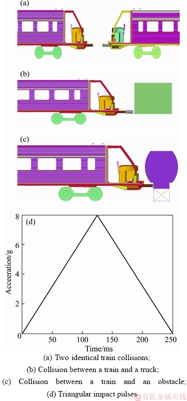
Figure 3 Different collision scenarios:
4 Collision scenarios for simulation of driver secondary impact
In order to evaluate the driver injury severity in the secondary impact, the first step is to define a reasonable collision scenario. Due to this reason, several widely used collision scenarios are chosen and compared, for example, the collision scenarios defined in the standard EN15227 [18] (two identical train collision, collision between a train and a truck, collision between a train and an obstacle) and the triangular impact pulses defined in US 49CFR [19], as shown in Figure 3.
According to the simulation results, it can be found that the kinematics of the driver by different collision scenarios is essentially the same. Taking the triangular impact pulse for example (Figure 4), at beginning t=0, the driver sits on the chair with two arms lying on the control desk and legs on the pedal. From t=0 to 0.16 s, the driver leans forwards to the control desk under the increased impact pulse. Besides that, the driver��s hands are in contact with the screens, and the chest is also in contact with the control desk. At t=0.19 s, the driver��s upper limb keeps leaning forwards, and the hip lifts up progressively. Finally, when the driver leans forwards further, his head strikes the control desk and then rebounds back.
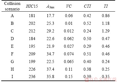
The driver injury severity by different collision scenarios are evaluated and summarized in Table 1. It can be seen clearly all injury criteria are under the limits defined in the standard GM/RT2100, which means the driver is well protected by the existing structural design. Besides that, the driver injury criteria subjected to the triangular impact pulses are larger than those by the collision scenarios defined in EN15227. Due to this reason, the most serious collision scenario (triangular impact pulse) is proposed for the study on the driver secondary impact.

Figure 4 Driver motion under triangular impact pulse:
Table 1 Driver injury criteria by different collision scenarios

5 Train driver protections under secondary impact
In this section the triangular impact pulse is adopted for the further study on the driver protections under secondary impact. Two measures are proposed to reduce the driver injury severity, such as optimization of the driver seat position and equipping the train with three-point seat belt.
5.1 Multi-objective optimization of driver seat position
5.1.1 Response surface models
In order to comprehensively analyse the influence of the driver seat position on the driver injury severity, some surrogated models are constructed according to the flowchart shown in Figure 5. The longitudinal and vertical distances between the driver seat and control desk (Figure 6) are selected as design variables, whose ranges according to the UIC651 [20] are: 0.35 m��x1��0.45 m, 0.15 m��x2��0.25 m. Based on a 2-factor with 3-level experiment design, three longitudinal distance (0.35 m, 0.4 m, 0.45 m) and three vertical distance (0.15 m, 0.2 m, 0.25 m) between the driver seat and control desk are chosen. As a result, there are nine scenarios simulated in this section, namely A(0.35, 0.15), B(0.4, 0.15), C(0.45, 0.15), D(0.35, 0.2), E(0.4, 0.2), F(0.45, 0.2), G(0.35, 0.25), H(0.4, 0.25), I(0.45, 0.25).

Figure 5 Flowchart of approximate model

Figure 6 Schematic diagram of driver seat position
The driver motions by different seat positions are shown in Figure 7. At the beginning, the acceleration of the impact pulse increases linearly and the drivers lean forwards. At the time of 0.13 s, the chests of all the drivers are in contact with the control desks. At the time of 0.19 s, the heads of drivers in scenario G, H and I impact the control desks. When the simulations run to the time of 0.23 s, the head forward movements in scenario A, B, C, D, E and F reach their maximum degree but without contact with the control desks. On the other hand, the driver��s heads in scenario G, H and I rebound upwards after hitting the control desks.

Figure 7 Driver motions by different driver seat positions:
The driver injury criteria by different seat positions are summarized in Table 2. Based on these simulation results, the response surface (RS) method is adopted to construct polynomial approximations of the driver injury criteria (HIC15, VC and TI) with the two input variables x1 (longitudinal distance) and x2 (vertical distance). These approximations are constructed using the second order polynomial regression models, and are represented as:

 (5)
(5)

 (6)
(6)

 (7)
(7)
Table 2 Driver injury criteria by different driver seat positions
In order to validate and check the accuracy of the constructed RS models, 9 verification points are generated. Figure 8 shows the comparisons between the simulations and RS models. It can be seen the results from the RS models are in a good correlation with the simulation results and the high values of R2 also indicate that the RS models are reliable in predicting the driver injury criteria.
According to the constructed RS models, the relationships between the driver injury criteria and driver seat positions are shown in Figure 9. It can be found that the driver seat positions have different effects on different injury criteria. Generally, the HIC15 criterion is proportional to the longitudinal and vertical distance between the driver seat and control desk; and the TI criterion is inversely proportional to the longitudinal distance and proportional to the vertical distance. In terms of the VC criterion, it is more complicated and its minimal value is about 0.006 at the position of (0.35, 0.21). Due to this reason, the driver seat position should be properly arranged according to the primary protected organ of the train driver (head, chest or leg).

Figure 8 Comparisons between RS models and simulation results:

Figure 9 Relationships between driver injury criteria and driver seat positions:
5.1.2 Pareto solutions with NSGA-II
The aim of the driver seat position optimization is to find a set of values of factors x1 (longitudinal distance) and x2 (vertical distance) that can efficiently reduce the driver��s injury criteria (HIC15, VC and TI). The optimization problem can be described in a multi-objective framework:
 (8)
(8)
In multi-objective optimization, there typically does not exist a feasible solution that minimizes all objective functions simultaneously. Therefore, attention is paid to Pareto optimal solutions which cannot be improved in any of the objectives without degrading at least one of the other objectives. In order to obtain the Pareto solutions, the non- dominated sorting genetic algorithm II (NSGA-II) is adopted in this section to analyse the surrogate RS models. The number of individual elements in the initial populations is 12 and the number of generations is 20.
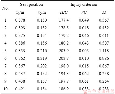
Based on the calculated Pareto solutions, the driver seat positions with the first 10% minimal values of each injury criterion are shown in Figure 10. These solutions are very helpful for engineers to design the driver control desk. For example, when the protection of driver head injury is the major objective, the optimal longitudinal and vertical distances between the driver seat and control desk are about 0.37 m and 0.15 m respectively. As a result, the Pareto solutions with the numbers 1-4 (Table 3) are suggested. In terms of the driver chest and leg protection, the optimal driver seat positions are about (0.36 m, 0.21 m) and (0.43 m, 0.15 m), respectively, and the Pareto solutions with the numbers 5�C7 and 8�C10 are suggested correspondingly.

Figure 10 Pareto solutions with first 10% minimal values of each injury criterion
Table 3 Suggested Pareto solutions for design of driver seat position
5.2 Equipping with seat belt
5.2.1 Two or three-point seat belt
The seat belt is successfully adopted in the passive safety of automobile industry and it has saved numerous lives from the traffic accidents all over the world. However, until now the train is still not equipped with the seat belt, neither for the train drivers nor the passengers. As a result, the effects of seat belt on the driver injuries are comprehensively analysed in this section.
According to the simulation results in Figure 11(a), the driver without seat belt moves forwards under the effect of impact pulse and his head rebounds upwards after hitting the control desk. As the abdomen of the driver wearing two-point seat belt (Figure 11(b)) is constrained to the seat, the lower limbs move only slightly. By contrast, the driver��s upper body leans forwards significantly, resulting in his head hitting the control desk more seriously than that of the driver without seat belt. In terms of the driver with three-point belt (Figure 11(c)), not only the abdomen but also the chest and shoulder are well constrained to the seat, the driver��s forwards movement under the secondary impact is largely decreased. Due to this reason, the driver��s head is well protected and does not hit the control desk.
These theoretical analyses are well in accordance with the driver injury criteria shown in Figure 12. It can be seen that the driver with three-point seat belt is well protected under the secondary impact and all the injury criteria are smaller than those of the driver without seat belt. In terms of the driver with two-point seat belt, due to the slight movement of the lower limbs but a strong impact between his head and control desk, the chest and leg injury criteria (VC and TI) are the lowest, whereas the head injury criterion HIC15 is the largest (increased about 42%). Therefore, with an overall consideration, the three-point seat belt is suggested for the train driver protection under the secondary impact.
5.2.2 Limited load of three-point seat belt
Although it is important to equip the train with three-point seat belt to reduce the driver injury under the secondary impact, it is also as important to ensure that this seat belt system itself does not cause any harm. The load limiter is a key component of the seat belt system, which is designed to reduce the seatbelt-induced injuries such as rib fractures by allowing the forwards movement of occupants�� torsos when the seat belt load exceeds the threshold. As a result, different thresholds of the load limiter are simulated and their effects on the driver injuries are shown in Figure 13. It can be seen that, in generally, compared with the driver leg injury, the limited load has larger influences on the driver head and chest injuries; and in terms of the driver chest injury, the VC criterion is proportional to the limited load. The relationship between the limited load and the driver head injury is more complicated. When the limited load is relative small the head injury HIC 15 is inversely proportional to the limited load, for example, the HIC 15 has the largest value about 192 when the limited load is only 0.5 kN. Besides that, when it exceeds 1.5 kN, the HIC15 criterion increases slightly with the increased limited load. Therefore, with an overall consideration that all driver injury criteria (head, chest and leg) are relative small under the secondary impact, the limited load of the seat belt is suggested about 1.5 kN.

Figure 11 Driver responses:
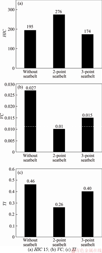
Figure 12 Driver injury criteria:

Figure 13 Driver injury criteria by different limited loads:
6 Conclusions
In this paper, an EMU train with detailed cab structure has been established based on the finite element method. The secondary impact between train driver and control desk is fully analysed and two measures are proposed to reduce the driver injury severity, such as the multi-objective optimization of the driver seat position and equipping the train with three-point seat belt. The main conclusions are summarized as:
1) According to the comparison of the injury criteria by different collision scenarios, the train driver suffers the most serious injury by the triangular impact pulse defined in the standard US CFR49.
2) The driver seat position has a significant effect on the driver injury severity during a secondary impact. When the protection of driver head injury is the major objective, the optimal longitudinal and vertical distances between the driver seat and control desk are about 0.37 m and 0.15 m respectively. In terms of the driver chest and leg protection, the optimal driver seat positions are about (0.36 m, 0.21 m) and (0.43 m, 0.15 m), respectively. Besides that, according to the multi-objective optimization, some Pareto solutions are also suggested to design the driver seat position.
3) Simulation results indicate that although the chest and leg are well protected when the driver wears a two-point seat belt, it increases the head injure during a secondary impact. On the other hand, the three-point seat belt can supply the train driver with an overall protection against the secondary impact. The injury criteria (HIC15, VC, TI) of the driver with the three-point seat belt is significantly lower than those of the driver without seat belt. Due to this reason, it is suggested to equip the train with the three-point seat belt. Moreover, according to the simulation analysis, the limited load of the three-point seat belt is suggested about 1.5 kN.
References
[1] XUE X, SMITH R A, SCHMID F. Analysis of crush behaviours of a rail cab car and structural modifications for improved crashworthiness [J]. International Journal of Crashworthiness, 2005, 10(2): 125�C136.
[2] GAO Guang-jun, TIAN Hong-qi. Train��s crashworthiness design and collision analysis [J]. International Journal of Crashworthiness, 2007, 12(1): 21�C28.
[3] ZHANG Zhi-xin. Research on crashworthy structures and collision safety for high-speed trains [D]. Chengdu: Southwest Jiaotong University, 2012. (in Chinese)
[4] SCHOLES A, LEWIS J H. Development of crashworthiness for railway vehicle structures [J]. Proceedings of the Institution of Mechanical Engineers, Part F: Journal of Rail and Rapid Transit, 1993, 207(1): 1�C16.
[5] WANG Wen-bin, HECHT M, ZHOU He-chao. A simulation method of crashworthy train set [C]// 2011 IEEE International Conference on Computer Science and Automation Engineering. Chongqing, China: IEEE, 2011: 297�C301.
[6] ZOU Xiang, GAO Guang-jun, ZHANG Jie, ZHOU Xi-sai, CHEN Wei, GUAN Wei-yuan. A comparative crashworthiness analysis of multi-cell polygonal tubes under axial and oblique loads [J]. Journal of Central South University, 2017, 24(9): 2198�C2208.
[7] TYRELL D C, SEVERSON K J, MARQUIS B P. Train crashworthiness design for occupant survivability [C]// International Mechanical Engineering Congress and Exposition. San Francisco, US, 1995: 59�C78.
[8] TYRELL D C, SEVERSON K J, MARQUIS B P. Analysis of occupant protection strategies in train collisions [C]// International Mechanical Engineering Congress and Exposition. San Francisco, US, 1995: 539�C557.
[9] TYRELL D C. US rail equipment crashworthiness standards [J]. Proceedings of the Institution of Mechanical Engineers, Part F: Journal of Rail and Rapid Transit, 2002, 216(2): 123�C130.
[10] HECHT M. The crashworthiness of tramcar and LRV [J]. Foreign Rolling Stock, 2005, 42(5): 39�C41.
[11] CHEVALIER M C, MAUPAS A, LEVEQUE D. Air-bag protection of the train driver during a collision [C]// Proceedings of the 2005 International IRCOBI Conference on the Biomechanics of Impact. Prague, Czech Republic: IRCOBI, 2005: 447�C450.
[12] EAMES A. Optimising driving cab design for driver protection in a collision (debris ingress) [R]. Transportation Research Board, T190 Report, 2007.
[13] DUBRULLE A H, ROBACHE F, DRAZETIC P. Analysis of train driver protection in rail collisions: Part I. Evaluation of injury outcome for train driver in desk impact [J]. International Journal of Crashworthiness, 2013, 18(2): 183�C193.
[14] DUBRULLE A H, ROBACHE F, DRAZETIC P. Analysis of train driver protection in rail collisions: Part II. Design of a desk with improved crashworthiness performance [J]. International Journal of Crashworthiness, 2013, 18(2): 194�C205.
[15] ZHANG Sheng. Design and optimization of combined structure driver cab of high speed train [D]. Changsha: National University of Defense Technology, 2005. (in Chinese)
[16] HAO Meng. Finite element analysis and optimization design of a car rear seat [D]. Changchun: Jilin University, 2013. (in Chinese)
[17] GM/RT2100. Structural requirements for railway vehicle [S]. 2012.
[18] EN 15227. Railway applications-Crashworthiness requirements for railway vehicle bodies [S]. 2008.
[19] Code of Federal Regulation, Title49, Part571. Federal Motor Vehicle Safety Standard No.208, Occupant Crash Protection [S]. 2002.
[20] UIC 651. Layout of driver��s cabs in locomotives, railcars, multiple unit trains and driving trailers [S]. 2002.
(Edited by HE Yun-bin)
���ĵ���
��ʻԱ������ײ������ʩ�о�
ժҪ��ͨ������ij�Ͷ������г���ײ����Ԫģ�ͣ�ȫ��������г���ʻԱ�����̨֮��Ķ�����ײ��������˼����ʻԱ������ײ�˺������������ʩ�����Լ�ʻԱ����λ�õĶ�Ŀ���Ż����䱸����ʽ��ȫ������������������ʻԱ����λ�öԼ�ʻԱ�ڶ�����ײ�е����˳̶�������Ӱ�졣���ݶ�Ŀ���Ż�����������˻��ڼ�ʻԱ��ͬ������λ�����������Ž⣬Ϊ�����Ա���������ʻԱ�����ṩ��ָ�������⣬�о���������ʽ��ȫ����Ȼ�ܹ��ܺõر�����ʻԱ���ز����Ȳ����������Ӽ�ʻԱ������ײʱ��ͷ���˺���������ʽ��ȫ�����ܶ��г���ʻԱ�ṩ��ȫ��ı�����������ˣ������о���һ����������ʻԱ�䱸������ʽ��ȫ���������Ӧ����Ϊ1.5 kN��
�ؼ��ʣ��г���ײ��������ײ����ʻԱ��������Ŀ���Ż�������ʽ��ȫ��
Foundation item: Project(51805374) supported by the National Natural Science Foundation of China; Project(22120180531) supported by the Fundamental Research Funds for the Central Universities, China; Project(16PJ1409500) supported by the Shanghai Pujiang Program, China
Received date: 2017-04-18; Accepted date: 2018-05-21
Corresponding author: ZHOU He-chao, PhD, Assistant Professor; Tel: +86-21-69584712; E-mail: zhouhechao@tongji.edu.cn; ORCID: 0000-0003-2722-922x

