�軯��������Ͻ�������������Ӳ�ȡ�����ģ���Ͷ������Ե�Ӱ��
��Դ�ڿ����й���ɫ����ѧ��(Ӣ�İ�)2021���3��
�������ߣ�N. MAKUCH
����ҳ�룺764 - 778
Key words��gas boriding; hardness; elastic modulus; nanoindentation; fracture toughness
ժ Ҫ����N2-H2-BCl3�����¶�����Ͻ����������������(910 ��C��2 h)�Ʊ�˫���㡣����֯�����־��в�ͬ��ɷֵ�������ɡ������������������Ļ���� (Ni2B, Ni3B)���ڲ�����������������й軯��(Ni2Si, Ni3Si)���о��軯���Ĵ��ڶ������Ͻ��������ѧ���ܵ�Ӱ�졣ʹ�ô���Berkovich���ʯѹͷ������ѹ������50 mN�غ��²���Ӳ�Ⱥ͵���ģ���������ʾ����������ƽ��ѹ��Ӳ�Ⱥ�ѹ�۵���ģ��ֵ�ֱ�Ϊ(16.32��1.03) GPa��(232��16.15) GPa���ڲ������й軯���Ĵ��ڽ�����ѹ��Ӳ��(6.8~12.54 GPa)�͵���ģ��(111.79~153.99 GPa)������ά��ѹ�۷��о�����0.981 N�غ��µĶ������ԡ�����������軯���Ĵ���ʹ���������Ĵ�������(Լ40%)��
Abstract: The two-stage gas boriding in N2-H2-BCl3 atmosphere was applied to producing a two-zoned borided layer on Nisil-alloy. The process was carried out at 910 ��C for 2 h. The microstructure consisted of two zones differing in their phase composition. The outer layer contained only a mixture of nickel borides (Ni2B, Ni3B) only. The inner zone contained additionally nickel silicides (Ni2Si, Ni3Si) occurring together with nickel borides. The aim of this study was to determine the presence of nickel silicides on the mechanical properties of the borided layer produced on Ni-based alloy. The hardness and elastic modulus were measured using the nanoindenter with a Berkovich diamond tip under a load of 50 mN. The average values of indentation hardness (HI) and indentation elastic modulus (EI) obtained in the outer zone were respectively (16.32��1.03) GPa and (232��16.15) GPa. The presence of nickel silicides in the inner zone reduced the indentation hardness (6.8-12.54 GPa) and elastic modulus (111.79-153.99 GPa). The fracture toughness of the boride layers was investigated using a Vickers microindentation under a load of 0.981 N. It was confirmed that the presence of nickel silicides caused an increase in brittleness (by about 40%) of the gas-borided layer.
Trans. Nonferrous Met. Soc. China 31(2021) 764-778
N. MAKUCH
Poznan University of Technology, Institute of Materials Science and Engineering, Pl. M. Sklodowskiej-Curie 5, 60-965 Poznan, Poland
Received 5 May 2020; accepted 28 December 2020
Abstract: The two-stage gas boriding in N2-H2-BCl3 atmosphere was applied to producing a two-zoned borided layer on Nisil-alloy. The process was carried out at 910 ��C for 2 h. The microstructure consisted of two zones differing in their phase composition. The outer layer contained only a mixture of nickel borides (Ni2B, Ni3B) only. The inner zone contained additionally nickel silicides (Ni2Si, Ni3Si) occurring together with nickel borides. The aim of this study was to determine the presence of nickel silicides on the mechanical properties of the borided layer produced on Ni-based alloy. The hardness and elastic modulus were measured using the nanoindenter with a Berkovich diamond tip under a load of 50 mN. The average values of indentation hardness (HI) and indentation elastic modulus (EI) obtained in the outer zone were respectively (16.32��1.03) GPa and (232��16.15) GPa. The presence of nickel silicides in the inner zone reduced the indentation hardness (6.8-12.54 GPa) and elastic modulus (111.79-153.99 GPa). The fracture toughness of the boride layers was investigated using a Vickers microindentation under a load of 0.981 N. It was confirmed that the presence of nickel silicides caused an increase in brittleness (by about 40%) of the gas-borided layer.
Key words: gas boriding; hardness; elastic modulus; nanoindentation; fracture toughness
1 Introduction
Boronizing is well-known as a process that improved the hardness and wear resistance of pure nickel and its alloys. Nickel-based alloys can be boronized efficiently by various techniques [1]. Depending on the chemical composition of the nickel alloy, different types of borides may be formed, e.g. nickel borides, chromium borides, iron borides or cobalt borides. Phase composition was an important factor influencing the properties of the produced layer. For this reason, the selections of the substrate material, as well as the composition of the boron source used for the boriding of Ni-based alloys, were also significant. In the case of boriding with the use of the agents containing SiC, a silicide zone was formed [2-5]. The produced nickel silicides were characterized by a high degree of porosity and a reduced hardness in comparison to the nickel borides. In Ref. [2], the SiC was used in the powder mixture as a diluent during boriding of 99.9% pure nickel. As a consequence, the multi-component layers also contained nickel silicides (Ni2Si, Ni3Si or Ni5Si2). The presence of porous nickel silicides was the reason for a hardness diminishing to HV 832. However, the nickel boride zone was characterized by a higher hardness of HV 984 [2]. A similar effect was observed when the Nimonic 90 superalloy was silicon-boronized [4]. The produced chromium borides were characterized by the highest hardness of HV 2082, and the lowest hardness of HV 996 was measured for (Ni,Co)5Si2 silicide.
In many literature data [6-9], the advantageous properties of nickel silicides were reported. Generally, the production of nickel silicides on the surface of Ni-based alloys has been found to be an attractive method of protection against wear, corrosion and oxidation. The excellent corrosion resistance and oxidation resistance of nickel silicides resulted from the formation of a protective silicon oxide layer on their surface [9]. The resistance of nickel silicides to an aggressive environments at elevated temperature caused these intermetallic compounds to be applied in advanced industrial gas turbines, internal combustion engines and power generation plant. Nickel silicides were also used in microelectronics as interconnectors, ohmic contacts and gate materials for integrated circuits [8]. Unfortunately, nickel silicides (especially Ni3Si) became brittle at the grain boundaries at room temperature, which may limit their use as a protective surface layers [10-13]. However, the addition of alloying elements, e.g. Ti, Cr or B, may improve this disadvantage [10-13].
In the case of borided layers, their main disadvantage was susceptibility to cracking. The brittleness of the borided layer strongly depended on its phase composition. The borided layers produced on the nickel-based alloys differed in mechanical properties, such as hardness, elastic moduli and fracture toughness. It was found that in the case of borided nickel alloys, the content of chromium in the base material was an important factor influencing the fracture toughness of the plasma paste borided layers [14]. As a result of plasma paste boriding of pure Ni, the produced layer consisted only of nickel borides. This phase composition of the boride layer ensured the lowest hardness and the lowest brittleness (Kc=1.48 MPa��m1/2). The increase in the chromium content in the base material resulted in a decrease in the fracture toughness of the borided layers due to the presence of chromium borides. Therefore, the average Kc value obtained for the boride layer produced on Inconel 600 alloy (chromium content of 15.72 wt.%), was equal to 0.72 MPa��m1/2. In the case of an increase in the Cr content in the nickel alloy up to 19.52 wt.% (Nimonic 80A alloy), the brittleness increased significantly (Kc= 0.53 MPa��m1/2) [14].
According to the literature data, many boriding methods resulted in the formation of a surface layer containing nickel silicides, e.g. powder agents used for pack boriding [2-5]. Many authors emphasized that nickel silicides appearing in the borided layer produced on nickel or its alloys caused an increase in porosity, as well as a decrease in the hardness of the borided layer. However, the main problem of nickel silicides�� presence in the borided layer seems to be an increased brittleness. Unfortunately, the influence of nickel silicides on the brittleness of the borided layers produced on nickel and its alloys is still unknown. The knowledge concerning this above mentioned problem is an important factor that can seriously limit the use of the boriding agents favoring the presence of nickel silicides after boriding of nickel and its alloys. On the other hand, many literature data [4,9,15] reported the advantageous effect of modification of nickel silicides (e.g. with Ti or Cr addition) in order to reduce the brittleness. Hence, the boriding process which caused production of nickel borides could reduce the brittleness of the nickel silicides. Therefore, in this study, the fracture toughness was measured for nickel silicides free layer and the nickel silicides rich layer. Two-stage gas boriding in the N2-H2-BCl3 atmosphere was used for the formation of a surface layer composed of nickel borides and nickel silicides. The influence of the presence of nickel silicides (Ni3Si and Ni2Si) on hardness, elastic modulus and fracture toughness of the borided layer was studied and discussed in detail.
2 Experimental
2.1 Material
Nisil-alloy was selected as an experimental substrate material. Nisil is a well-known alloy, usually used as a thermocouple material. Its chemical composition is as follows: 95.5 wt.% Ni, 4.4 wt.% Si and 0.1 wt.% Mg.
2.2 Two-stage gas boriding
The devices used for gas boriding were presented and described in detail in previous studies [16,17]. The process was carried out in the N2-H2-BCl3 atmosphere at 910 ��C (1183 K) for 2 h. The two-stage process was applied. The first stage consisted of the diffusion saturation of the surface with boron and its diffusion into the treated material. During this stage, the boron trichloride was added to the N2-H2 atmosphere for 15 min in order to produce the free boron atoms, which were absorbed by the surface and diffused into the workpiece. The second stage consisted of diffusion annealing excluding the addition of boron trichloride for 15 min, and the gas atmosphere contained only a mixture of nitrogen and hydrogen. During this stage, only the diffusion of boron occurred without the producing of the further free atoms of boron. One cycle consisted of two stages: first was saturation with boron and the second was diffusion annealing. The two-stage cycle was repeated four times during the boriding process. Therefore, the total duration of the process was 2 h. The content of boron trichloride was an important process parameter. The amount of BCl3 in the boriding atmosphere (N2-H2-BCl3) resulted from its vapor pressure depending on the temperature. The general equation describing the change in the vapor pressure of boron trichloride with temperature was as follows:
 (1)
(1)
where p is the vapor pressure (��0.133 kPa), and T is the temperature (K).
The vapor pressure of boron trichloride was calculated respectively as a function of temperature using Eq. (1). The content of BCl3 in the gas atmosphere depended on the relationship between temperature and the equilibrium vapor pressure of boron trichloride. The dependence of BCl3 content in the entire gas atmosphere on the temperature is shown in Fig. 1(a). Obviously, the increase in the temperature of boron trichloride caused an increase in its vapor pressure up to an initial boiling point of 13 ��C (286 K). The cylinder with boron trichloride was placed into the cryostat in order to cool to a low temperature ranging from -62 to -59 ��C (211-214 K). The content of BCl3 during the two-stage gas boriding process is shown in Fig. 1(b). The average boron trichloride content was equal to 8.6 vol.% in relation to hydrogen, and 2.3 vol.% in relation to the entire atmosphere N2-H2-BCl3 used. After the boriding process was finished, the samples were cooled in a protective nitrogen atmosphere.
2.3 Metalographical preparation and micro- structure observations
Borided samples were sectioned and polished for metallographic characterization. In order to reveal details of the microstructure of the gas-borided sample, the Marble��s etchant was used. The morphology and microstructure of the boride layer were analyzed using scanning electron microscope MIRA3 Tescan, and the distribution of the selected elements was analyzed by energy dispersive X-ray spectroscopy (EDS). During the X-ray micro- analysis, the following parameters were used: accelerating voltage of 12 kV, 55�� take-off angle, and Si (Li) detector with an ultra-thin window. Simultaneously, standardless quantitative analysis, and ZAF matrix correction algorithms for SEM bulk analysis were applied. The porosity of the boride layer was determined on the cross-section of the sample with the use of a digital microscope Keyence VHX-6000.
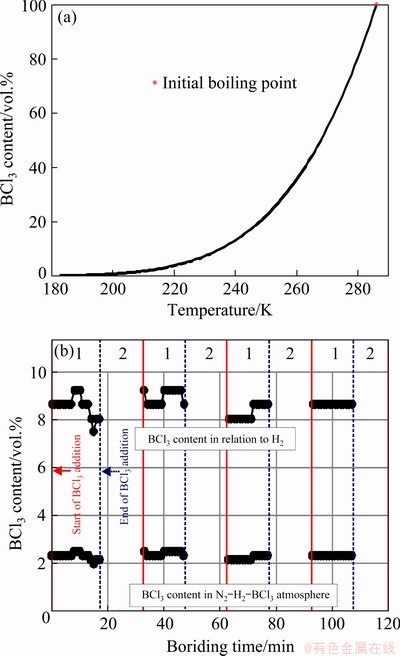
Fig. 1 Dependence of BCl3 content on temperature (a) and scheme of two-stage BCl3 addition during gas boronizing in N2-H2-BCl3 atmosphere (b)
2.4 Nanoindentation procedure
The measurements of nanomechanical properties were performed on the cross-section of the etched sample. The investigated areas consisted of nickel borides and mixture of nickel borides and nickel silicides. The instrumented indentation tests were carried out using an Anton Paar Nano- indentation Tester NHT3. A Berkovich diamond tip under a maximal load of 50 mN was used for investigations. During the measurements, the indentation load F and the penetration depth h (displacement) were recorded continuously. The detailed experimental procedure used for nano- indentation measurements, as well as equations used for calculation of mechanical properties were presented in previous studies [18-20]. The basis for the mechanical properties estimation was the unloading behavior, in accordance with the OLIVER and PHARR standard [21]. Based on the obtained indentation curves (load�Cdisplacement curves), the following properties were calculated: indentation hardness (HI), Vickers hardness (HV), indentation elastic modulus (EI), maximal penetration depth (hmax) and the ratio of the permanent penetration depth hp to the maximal penetration depth hmax (hp/hmax ratio).
2.5 Fracture toughness measurement
The main disadvantage of the hard ceramic phases, occurring in the surface layers, is their brittleness. According to the literature data, various conventional methods could be used to determine fracture toughness, e.g. a chevron notch bar, a single-edge-precracked beam, a single-edge notched beam or a double cantilever beam [22]. However, the most popular method for the brittleness evaluation of surface layers is Vickers indentation fracture, because of its efficiency. Moreover, in the case of surface layers, this method is considered much simpler and relatively more accurate [22,23]. Since the Vickers indentation toughness results from a different cracking systems, many authors suggest the determination of the cracking mode (radial-median, Palmqvist or intermediate), as a preliminary investigation [23,24].
The aim of fracture toughness investigations was to determine the influence of the nickel silicides presence on the brittleness of the gas-borided layer produced on the Ni-based alloy. Therefore, measurements were performed in the area containing only nickel borides and in the area consisting of nickel borides and nickel silicides. In order to identify the area of investigations, the fracture toughness was measured in the etched cross-section of the gas-borided sample. The standard Vickers method of hardness measurements was used to evaluate the fracture toughness. The Vickers microindentation tests were carried out with the apparatus ZWICK 3212 B.
First, in order to evaluate the type of cracking mode (radial-median, Palmqvist or intermediate), different indentation loads were used (0.981, 1.962, 2.943, 3.924 and 4.905 N). Then, the Vickers microindentation fracture toughness was measured using the lowest indentation load of 0.981 N. Fifteen measurements were carried out for both zones occurring in the gas-borided layer.
During the fracture toughness measurements, the microcracks were usually generated from the corners, according to the scheme shown in Fig. 2(a). The diagonal lengths 2a and the lengths of the cracks generated L1, L2, L3 and L4 were measured using an optical microscope Opta Tech Lab40 equipped with a digital camera and a computer. First, the images, including the Vickers indentations with the generated cracks, were observed using RT 16 series camera and then registered by the Opta View software. The images of a high resolution and quality were generated. The Opta View software enabled to measure the length, width or surface area. High image resolution and software allowed for lengths measurement with an accuracy of 0.001 ��m. However, in order to simplify the calculation of the fracture toughness, the accuracy of 0.01 ��m was applied. The accuracy of Kc factor values resulted only from the mathematical equation. In this case, it was possible to present the obtained results with high accuracy (even up to 10-6 MPa��m1/2). However, such a high accuracy could be questionable. Therefore, the values of Kc were limited to the accuracy of 0.01 MPa��m1/2, as reported in the previous published studies [17,20]. Additionally, standard deviations were given.

Fig. 2 Schematic views of obtained Vickers indentation marks and cracks
The Kc was calculated on the basis of the radial-median crack model shown in Fig. 2(b). In the case of a radial-median cracking mode, the cracks were visible on the top view of the sample, as well as a characteristic half-penny substructure appeared on the cross-section (Fig. 2(b)). Based on the radial-median crack model, the fracture toughness (Kc) was calculated according to the equations:
 (2)
(2)
A=0.028(E/H)1/2 (3)
where P is Vickers microindentation load (N), c is the crack length from the center of the indentation mark to the end of the crack (m), A is the residual indentation coefficient, E is the elastic modulus of tested material (MPa), and H is the hardness of tested material (MPa).
The knowledge of the value of elastic modulus was required to calculate the fracture toughness Kc. The average values of the indentation elastic modulus EI, estimated as a result of nanomechanical properties testing, were taken into calculations of fracture toughness. These values were equal to 232 GPa for the zone with nickel borides and 134.58 GPa for the zone with nickel borides and nickel silicides.
The microstructure of the borided layer with visible Vickers microindentation marks and the generated cracks was observed using an optical microscope (OM) and scanning electron micro-scope (SEM) Tescan Vega 5135. The chemical composition (Ni, Si and B content) of the tested areas was measured using the PGT Avalon X-ray microanalyzer equipped with EDS.
3 Results and discussion
3.1 Microstructure of gas-borided layer
The phase composition of the gas-borided layer produced on Nisil-alloy was presented in an earlier work [16]. The obtained XRD patterns of the borided specimen confirmed the presence of nickel borides (Ni2B and Ni3B) and nickel silicides (Ni2Si and Ni3Si). In order to identify the distribution of nickel borides and nickel silicides on the scross-section of the borided layer, the X-ray spectroscopy (EDS) was used. The BSE images of the gas-borided layer produced on Nisil-alloy are presented in Fig. 3. The EDS element mappings (for nickel, silicon and boron) were also presented. Two areas with significantly different layer composition were investigated. In Fig. 3(a) the gas-borided layer consisted of two zones: outer (1a) and inner (2). The results obtained showed that the outer layer (1a) contained a small amount of silicon in some regions; whereas, in the inner layer (2) a high concentration of silicon was detected. The outer layer contained only nickel borides (Ni2B and Ni3B). Beneath the nickel borides zone, the rich silicon zone consisted of a mixture of nickel borides (Ni2B and Ni3B) and nickel silicides (Ni2Si and Ni3Si).
The microstructure shown in Fig. 3(a) was predominant in the gas-borided layer produced on Nisil-alloy. However, in some regions (Fig. 3(b)), an increased concentration of silicon was detected in the outer zone (1b). This indicated the presence of some amount of nickel silicides in the outer zone of the gas-borided layer. During boriding, the silicon was moved in a core direction, following the boron diffusion front. In some areas of the outer zone, the silicon concentration was increased and appropriate for the formation of nickel silicides. Nickel silicides were formed in these areas. For this reason, the boron diffusion front could not move the silicon atoms that were bound in the nickel silicides. The phase composition of the gas-borided layer produced on Nisil-alloy was presented in the earlier work [16]. The average thickness of the gas-borided layer produced was 160 ��m; whereas, the outer layer containing nickel borides was only 80 ��m deep.
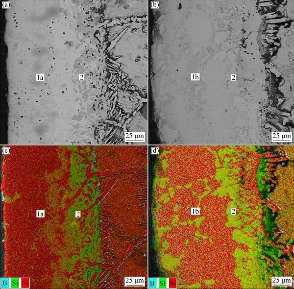
Fig. 3 BSE images of microstructure of gas-boride layer produced on Nisil-alloy (a, b) and corresponding EDS element mappings for nickel, silicon and boron (c, d)
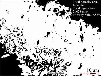
Fig. 4 Binary OM image of gas-borided layer produced on Nisil-alloy with results of porosity amount
The small amount of porosity was observed, especially in the inner layer (zone with nickel borides and nickel silicides). In order to evaluate the porosity, the binary OM image of the gas- borided layer (Fig. 4) was analyzed. The porosity amount of the borided layer formed on Nisil-alloy was measured, because the presence of the porosity could diminish the mechanical properties and increase the brittleness of the borided layer. The investigated area was characterized by a small amount of porosity equal to 7.86%. However, the pores were mainly detected in the inner zone, in which nickel silicides occurred. This specific distribution of pores could be the reason for increased brittleness in this zone.
3.2 Nanomechanical properties
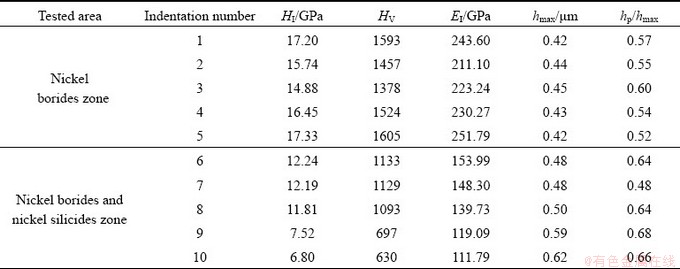
Five measurements were carried out in the outer nickel borides zone (Indentations 1-5), as well as in the inner zone (Indentations 6-10) in which nickel borides and nickel silicides were identified. The results of the nanoindentation measurements performed in both zones, are presented in Table 1. The presence of nickel silicides in the inner zone strongly influenced the obtained values of the maximal penetration depth hmax, hp/hmax ratio, the indentation hardness HI, as well as the indentation elastic modulus EI. The indentation marks performed in the outer zone were characterized by higher hardness (14.88-17.33 GPa) and higher elastic modulus (211.1-251.79 GPa). The presence of nickel silicides in the inner zone was the reason for HI diminishing (6.8-12.54 GPa) and EI diminishing (111.79-153.99 GPa). Lower values of the maximal penetration depth hmax were characteristics of the outer nickel borides zone. Simultaneously, the hp/hmax ratios were also lower. Therefore, these indentation marks had a lower projected area and higher hardness.
Table 1 Results of measurements using nanoindenter for borided Nisil-alloy
The microstructure and some properties of the borided layers containing nickel silicides were reported in Refs. [2-4]. The production of such two-component layers was the result of the simultaneous silicides during the boriding process. The reason for this situation was the chemical composition of the boriding agents, which contained SiC as a diluent. In the case of the pack-boriding of pure nickel [3] using Ekabor II powder (containing SiC), the layer produced consisted of two zones: the outer thick nickel silicides zone (281 ��m) and a thin nickel borides zone (about 10 ��m). The exterior silicide zone (containing Ni5Si2 phase) was characterized by the presence of porous and reduced hardness (HV 747-805). Similarly, in the case of silicon- boronizing of Nimonic 90 alloy with the use of a self-protective paste containing SiC, silicides were also formed [4]. The produced multilayer coating consisted of an outer silicides layer, an intermediate borides layer, and an inner layer of Ti-rich nickel silicide. First, high porosity and cracks were visible in the outer zone containing (Ni,Co)5Si2. Second, this phase composition influenced the hardness measured in each zone. The highest hardness (HV 1300-1400) was characteristic of borides zone. The presence of nickel silicides was the reason for hardness diminishing below HV 1000. The microhardness of the layers was only about 3 times higher than that of the substrate (Nimonic 90 alloy). The influence of the nickel silicides presence on the hardness reported in the literature data [2-4] correlated with the hardness values obtained in this study. The hardness measured in the nickel silicides zone was in the range from HV 630 to HV 1133. The values obtained in the nickel borides zone were comparable to those reported in Refs. [14,25]. In Ref. [25], the SiC-free boride agent (Ekabor Ni) was used for boriding of pure nickel. As a result, it was possible to obtain a thick boride layer without simultaneous siliconization. The produced single- phase Ni2B layer was characterized by a hardness of HV 1300. Plasma-paste boriding was appropriate method of producing silicides-free layers on pure nickel [14]. The produced layer contained only nickel borides (Ni2B, Ni3B). The nanoindentation measurements were carried out in the borided layer. The average indentation hardness HI measured in this layer was 17.97 GPa; whereas, the indentation elastic modulus ranged from 195.19 to 251.69 GPa. In the present study, the nickel borides zone contained the same types of nickel borides: Ni2B and Ni3B. As a consequence, comparable values of hardness and elastic modulus were obtained, as was reported in Ref. [14].
Generally, materials during indentation can represent two type of behavior: elastic or plastic. Based on the calculated hp/hmax ratio, the behavior of the tested material can be easily determined. If the material represents a group characterized by full elasticity, the hp/hmax ratio is equal to 0. For materials with full plastic behavior, the hp/hmax ratio is equal to 1. All the indentations generated in the gas-borided layer were characterized by complex elastic�Cplastic behavior. However, lower values were calculated for the outer zone (hp/hmax ratio ranging from 0.52 to 0.60), in which only nickel borides were identified. The indentation marks obtained in the inner zone were characterized by higher values of hp/hmax ratios (0.48-0.68). The presence of nickel silicides in this zone made this area slightly more prone to plastic deformation during indentation compared to the compact nickel borides zone.
3.3 Fracture toughness
3.3.1 Selection of cracking mode
Three types of cracking mode can characterize materials: radial-median [26,27], Palmqvist [14,28,29] and intermediate [24] cracking modes. These crack systems differ in top-view profile and cross-section profile. The use of each mode to calculate the fracture toughness required justification. The procedure used to determine the cracking mode was described in Ref. [24]. In general, the cracking mode can be established using the following proportionalities:
c~P2/3 for radial-median cracking mode (4)
L~P2(1-1/n) for Palmqvist cracking mode (5)
c~P[1/1.5-q(1-q/n)] for intermediate cracking mode (6)
where n is Mayer��s index, and q is the linear- dependence function, experimentally determined using ln c vs ln P plot.
In order to identify the cracking mode characterizing the gas-borided layer formed on Nisil-alloy, preliminary investigations were carried out. In this study, various indentation loads of 0.98, 1.96, 2.943, 3.924 and 4.905 N were applied. The measurements were carried out on the cross-section of the gas-borided specimen, and the indentation marks were generated in the compact nickel borides zone and separately in the zone composed of nickel borides and nickel silicides. The first step to identify of the cracking mode was the determination of the diagrams of crack length values (c or L) versus the load (P) plotted in bi-logarithmic coordinates. For this study, 10 measurements were carried out for each indentation load in both zones of gas-borided layer. For the preparation of the diagram, the average values of the crack lengths were assumed for each indentation load. The obtained diagrams of the crack lengths (c or L) versus the indentation load (P) were plotted in bi-logarithmic coordinates, and the slopes (s) of the straight lines, represented in the plots of ln(L or c) vs ln P, were calculated for each type of cracking mode. In Fig. 5, the results for nickel borides zone are presented, separately for the radial-median (Fig. 5(a)), Palmqvist (Fig. 5(b)) and intermediate (Fig. 5(c)) cracking modes.
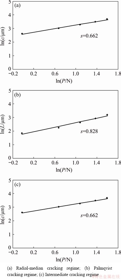
Fig. 5 Crack length criterion applied to results of outer zone of gas-borided layer formed on Nisil-alloy
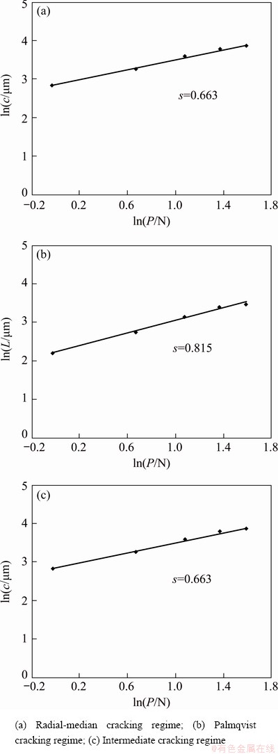
Fig. 6 Crack length criterion applied to results of inner zone of gas-borided layer formed on Nisil-alloy
The results, obtained for the inner zone containing nickel borides and nickel silicides, are shown in Fig. 6. The slope values s, obtained from Figs. 5 and 6, as well as the theoretical regimes for the radial-median, Palmqvist and intermediate cracking modes are summarized in Table 2. The obtained results indicated that the cracking mode can be identified as the radial-median for both zones of the gas-borided layer produced on Nisil-alloy. The slopes of the straight lines, represented in the plots of ln L versus ln P exhibited the values corresponding to the radial-median cracking mode regime according to Eq. (4).
3.3.2 Fracture toughness
In general, boride layers were characterized by high brittleness. Obviously, the phase composition of the borided layer strongly influenced its fracture toughness. The importance of the chromium borides presence for the brittleness of borided layers produced on nickel based alloy was earlier described [14]. However, in the case of the borided layers containing nickel silicides, their negative influence on brittleness could limit the use of boriding techniques. Therefore, in the present study, this problem was examined in detail.
The Vickers indentation fracture toughness was measured on a metallographic cross-section of a gas-borided layer produced on Nisil-alloy. This layer consisted of two zones differing in phase composition in such a way that the presence of nickel silicides (Ni2Si and Ni3Si) was confirmed only in the inner zone; whereas, the outer layer did not contain nickel silicides. Separate measurements for both zones allowed determining the influence of the nickel silicides presence on fracture toughness of the borided layer. Fifteen indentations were carried out for both zones occurred in the gas- borided layer produced on Nisil-alloy. The OM images of four selected Vickers indentation marks with the generated cracks are shown in Figs. 7 and 8, for the outer and inner zones, respectively. The results of the Vickers microindentation, as well as the calculated Kc values are presented in Tables 3 and 4, for the outer and inner zones, respectively.
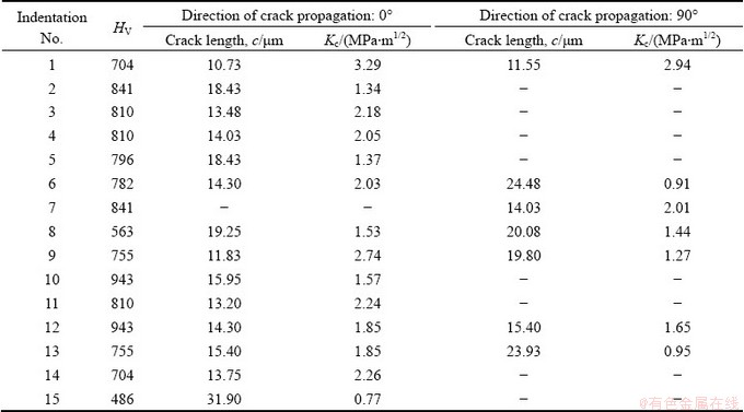
The Vickers microindentation marks with cracks, generated in the zone consisting only of nickel borides, are shown in Fig. 7. And Table 3 contains the results of all measurements obtained for this zone. Cracks occurred mainly in the direction parallel (0��) to surface (Figs. 7(b, c, d)). However, in the case of some indentations, the cracks were also visible in the perpendicular direction (90��) to the surface (Fig. 7(a)). The average values of Kc were (3.12��0.74) and (2.45��0.65) MPa��m1/2 for the considered direction 0�� and 90��, respectively. These results indicated a slight anisotropy of the fracture toughness measured in the zone including only nickel borides.
Table 2 Parameters used to determine cracking mode of borided layer produced on Nisil-alloy
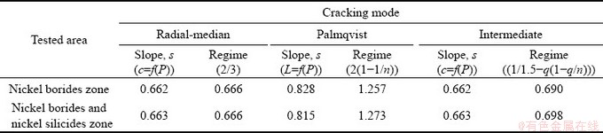
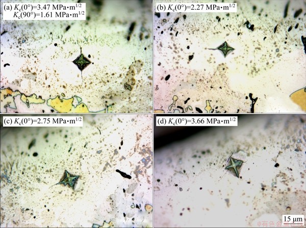
Fig. 7 OM images of four selected Vickers indentation marks with cracks produced in outer zone of gas-borided Nisil-alloy
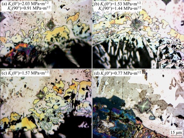
Fig. 8 OM images of four selected Vickers indentation marks with cracks produced in inner zone of gas-borided Nisil-alloy
Table 3 Results of measurements of Vickers hardness, crack lengths from centre of indentation mark to end of crack (c) and fracture toughness (Kc) for indentations obtained in nickel borides zone of borided layer produced on Nisil-alloy
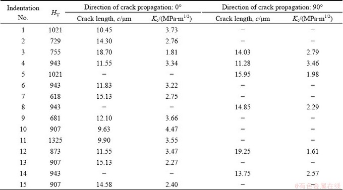
Table 4 Results of measurements of Vickers hardness, crack lengths from centre of indentation mark to end of crack (c) and fracture toughness (Kc) for indentations obtained in nickel borides and nickel silicides zone of borided layer produced on Nisil-alloy
It was obvious that the brittleness of the gas- borided layer depended on its phase composition. In the present study, nickel borides (Ni2B and Ni3B) were produced on the Nisil-alloy. These borides were characterized by similar values of thermal expansion coefficients (7.64��10-6 ��C-1 for Ni2B and 7.9��10-6 ��C-1 for Ni3B). Therefore, during cooling in nitrogen atmosphere, no compressive stresses occurred in the vicinity of the interface between nickel borides. In the case of the gas-borided layer consisting of a multiphase microstructure containing nickel borides and chromium borides [17], the difference in their thermal expansion coefficients was the reason for creation of compressive stress in the vicinity of the interface between nickel borides mixture and chromium borides mixture. Therefore, in the layer produced on Nimonic 80A alloy by gas boriding, strong compressive stresses occurred in the direction perpendicular (90��) to the top-surface. As a result, the propagation of cracks in this direction was retarded [17].
In order to determine the influence of nickel silicides presence on the fracture toughness of the gas-borided layer produced on Nisil-alloy, investigations were also carried out in the inner zone containing nickel borides (Ni2B, Ni3B) and nickel silicides (Ni2Si, Ni3Si). The Vickers microindentation marks with visible cracks, produced in the inner zone of the gas-borided layer are shown in Fig. 8. And Table 4 contains the results of fifteen measurements obtained for this zone. The cracks appeared mainly in the direction parallel (0��) to the surface (Figs. 8(c, d)). However, in the case of some indentations, the cracks were also visible in the direction perpendicular (90��) to the surface (Figs. 8(a, b)). The average values of the fracture toughness were (1.93��0.63) and (1.60��0.71) MPa��m1/2, for the direction 0�� and 90��, respectively. These results indicated that the presence of nickel silicides caused the decrease in the fracture toughness compared to the outer zone which did not contain nickel silicides. Simultaneously, the inner zone also indicated a slight anisotropy of fracture toughness, similarly to the outer zone. Longer cracks, as well as lower Kc were obtained in a direction parallel (0��) to the top-surface.
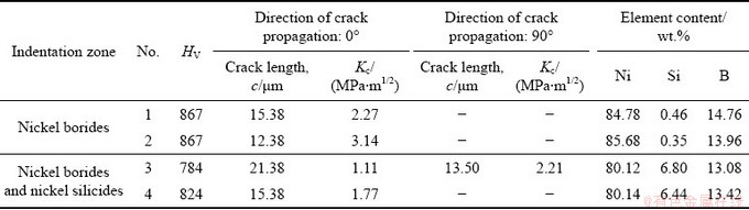
The investigations of Vickers microindentation fracture toughness were performed in two zones of the gas-borided layer. The depth of 80 ��m was assumed as the boundary between the outer and inner zones. The gas boriding process applied for Ni-based alloys caused the formation of a multiphase microstructure. Moreover, the small amount of porosity was observed in the inner zone. In this study, two types of microstructure were investigated: the outer zone composed only of nickel borides, and the inner zone composed of nickel borides and nickel silicides. The presence of borides Ni2B and Ni3B in the outer layer was confirmed by XRD phase analysis, as well as X-ray microanalysis. However, in some regions, the silicon rich areas were detected (according to Fig. 3(b)). It should be noted that the fracture toughness measurements in the outer layer were carried out only in the silicides-free areas (as shown in Fig. 3(a)). In order to ensure that the measurements of fracture toughness were performed in the silicides-free areas, an X-ray microanalysis was carried out. The BSE image of the gas-borided layer produced on Nisil-alloy with visible indentation marks is presented in Fig. 9. Two indentation marks (1 and 2) were obtained in the outer zone consisting of nickel borides mixture (Ni2B, Ni3B), and two indentation marks (3 and 4) were generated in the inner zone which additionally contained nickel silicides (Ni2Si, Ni3Si). The X-ray microanalysis was carried out in respect of the content of the following elements: Ni, Si and B. The obtained results of X-ray microanalysis for the indentations obtained in the borided layer (outer zone) produced on Nisil-alloy are presented in Table 5. The content of silicon in the outer borided layer was below 0.5 wt.%. This indicated the selection of appropriate areas for Kc measurements in the nickel borides zone (outer zone). Therefore, it is certain that the results of fracture toughness were obtained in this case only for the Ni-B system. On the other hand, the inner layer consisted of nickel borides (Ni2B and Ni3B) and nickel silicides (Ni2Si and Ni3Si). This was also confirmed by XRD phase analysis, as well as X-ray microanalysis. For indentation marks performed in the inner zone, a significantly increased content of silicon (above 6 wt.%) was detected. The results of the X-ray microanalysis confirmed that the inner zone contained nickel silicides. Vickers indentation marks were generated in this area, in order to detect the influence of nickel silicides presence on the brittleness of the borided layer. Due to the low porosity in the tested zone (inner layer), the area for Vickers indentation tests was carefully selected. Obviously, the porosity was visible in Figs. 8 and 9. However, it should be noted that indentations were only performed in the areas with low porosity.
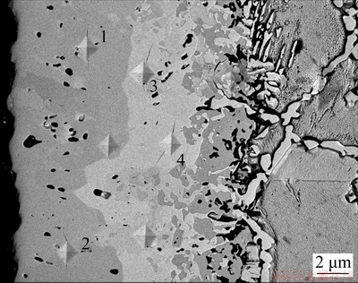
Fig. 9 BSE image of gas-borided layer produced on Nisil-alloy with visible Vickers indentation marks and cracks produced by fracture toughness measurements
Table 5 Results of measurements of Vickers hardness, crack lengths from center of indentation mark to end of crack (c), fracture toughness (Kc) and results of X-ray microanalysis for indentations obtained in borided layer produced on Nisil-alloy
Obviously, the results presented in this study concerned the multiphase microstructure: the outer layer contained nickel borides (Ni2B, Ni3B) and the inner layer consisted of mixture of nickel borides (Ni2B, Ni3B) and nickel silicides (Ni2Si, Ni3Si). In both cases, there was not possible to measure the fracture toughness in a separate phase due to the fine-grained microstructure. Moreover, it would be incorrect, because each layer had a compact structure in which the different phases together influenced the mechanical properties. In the present study, the inner and outer layers were considered as separate closed systems with a compact multiphase structure. Therefore, it was justified to measure their mechanical properties in relation to such compact closed systems.
4 Conclusions
(1) The presence of nickel silicides caused a decrease in indentation hardness ranging from 6.8 to 12.54 GPa.
(2) Lower value of indentation elastic modulus (111.79-153.99 GPa) was characteristic of the inner zone containing nickel silicides.
(3) During the fracture toughness measure- ments, the cracks were generated in both directions (0�� and 90��).
(4) The slight anisotropy of the fracture toughness occurred, in respect of the direction of cracks propagation. The higher fracture toughness was measured in a direction parallel (0��) to the top-surface.
(5) The presence of nickel silicides in the borided layer significantly reduced the fracture toughness. The values of Kc were about 40% lower than those obtained in the zone of nickel borides.
(6) In practice, the applying of boriding agents causing simultaneous siliconizing of Ni-based alloys should be limited due to the negative influence of nickel silicides.
(7) If the production of nickel silicides is necessary in order to increase the oxidation resistance, the boriding process could result in the formation of nickel borides, which were characterized by a higher fracture toughness than nickel silicides.
Acknowledgments
This work has been financially supported by Ministry of Science and Higher Education in Poland as a part of the Project No. 0513/SBAD.
References
[1] KULKA M. Current trends in boriding: Techniques [M]. Switzerland: Springer International Publishing, 2019.
[2] MU Dong, SHEN Bao-luo, YANG Chao, ZHAO Xin. Microstructure analysis of boronized pure nickel using boronizing powders with SiC as diluents [J]. Vacuum, 2009, 83: 1481-1484.
[3] OZBEK I, AKBULUT H, ZEYTIN S, BINDAL C, UCISIK A H. The characterization of borided 99.5% purity nickel [J]. Surface and Coatings Technology, 2000, 126: 166-170.
[4] LOU D C, AKSELSEN O M, SOLBERG J K, ONSOIEN M I, BERGET J, DAHL N. Silicon-boronising of Nimonic 90 superalloy [J]. Surface and Coatings Technology, 2006, 200: 3582-3589.
[5] GAONA-MARTINEZ M J, ALONSO-SAAVEDRA O F, RAMIREZ-RAMIREZ J H, CASTILLO-ELIZONDO J A, ZAPATA-HERNANDEZ O, PEREZ-GONZALEZ F A, GALLARDO-HERNANDEZ E A, COLAS R, GARZA- MONTES-DE-OCA N F. Mechanical stability of boron-based coatings grown on Incoloy 909 superalloy by thermochemical diffusion [J]. Surface Engineering, 2018, 34(7): 527-535.
[6] ALIZADEH M, NAROUEI S. Properties of Ni-Ni3Si composite coatings prepared by electrodeposition and subsequent heat treatment [J]. Journal of Alloys and Compounds, 2019, 772: 565-572.
[7] TAKASUGI T. Microstructural control and mechanical properties of nickel silicides [J]. Intermetallics, 2000, 8: 575-584.
[8] YOON Jin-Kook, BYUN Ji-Young, KIM Gyeung-Ho, LEE Jong-Kwon, YOON Ho-Sang, HONG Kyung-Tae. Formation process and microstructural evolution of Ni-silicide layers grown by chemical vapor deposition of Si on Ni substrates [J]. Surface and Coatings Technology, 2003, 168: 241-248.
[9] van DYCK S, DELAEY L, FROYEN L, BUEKENHOUTT L. Microstructural evolution and its influence on the mechanical properties of a nickel silicide based intermetallic alloy [J]. Intermetallics, 1997, 5: 137-145.
[10] TAKASUGI T, KAWAI H, KANENO Y. The effect of Cr addition on mechanical and chemical properties of Ni3Si alloys [J]. Materials Science and Engineering A, 2002, 329-331: 446-454.
[11] JANG J S C, WONG S K, LEE P Y. The effect of boron on the microstructure and mechanical behavior of an Ni-19Si- 3Nb based alloy [J]. Materials Science and Engineering A, 2000, 281: 17-22.
[12] JANG J S C, CHENG C Y, WANG S K. The effect of carbon microalloying on the microstructure and mechanical properties of a nickel silicide-based alloy [J]. Materials Chemistry and Physics, 2001, 72: 66-71.
[13] JANG J S C, OU C J, CHENG C Y. The evolution of microstructure change and mechanical properties for a nickel silicide based alloy doped with carbon and boron [J]. Materials Science and Engineering A, 2002, 329-331: 455-460.
[14] MAKUCH N, KULKA M, DZIARSKI P, TAKTAK S. The influence of chemical composition of Ni-based alloys on microstructure and mechanical properties of plasma paste borided layers [J]. Surface and Coatings Technology, 2019, 367: 187-202.
[15] LI Z, SCHULSON E M. Strength, hardness and fracture toughness of a complex nickel silicide containing ductile phase particles [J]. Journal of Materials Science, 1995, 30: 2859-2865.
[16] KULKA M, MAKUCH N, POPLAWSKI M. Two-stage gas boriding of Nisil in N2-H2-BCl3 atmosphere [J]. Surface and Coatings Technology, 2014, 244: 78-86.
[17] MAKUCH N, KULKA M. Fracture toughness of hard ceramic phases produced on Nimonic 80A-alloy by gas boriding [J]. Ceramics International, 2016, 42: 3275-3289.
[18] MAKUCH N. Nanomechanical properties and fracture toughness of hard ceramic layer produced by gas boriding of Inconel 600 alloy [J]. Transactions of Nonferrous Metals Society of China, 2020, 30: 428-448.
[19] KULKA M, MAKUCH N, DZIARSKI P, PIASECKI A. A study of nanoindentation for mechanical characterization of chromium and nickel borides�� mixtures formed by laser boriding [J]. Ceramics International, 2014, 40: 6083-6094.
[20] KULKA M, MAKUCH N, PIASECKI A. Nanomechanical characterization and fracture toughness of FeB and Fe2B iron borides produced by gas boriding of Armco iron [J]. Surface and Coatings Technology, 2017, 325: 515-532.
[21] OLIVER W C, PHARR G M. An improved technique for determining hardness and elastic 1modulus using load and displacement sensing indentation experiments [J]. Journal of Materials Research, 1992, 7(6): 1564-1583.
[22] KUTZ M. Handbook of measurement in science and engineering [M]. Volume 2. New Jersey: Wiley, 2013.
[23] CHICOT D, DUARTE G, TRICOTEAUX A. JORGOWSKI B, LERICHEB A, LESAGE J. Vickers indentation fracture (VIF) modeling to analyze multi-cracking toughness of titania, alumina and zirconia plasma sprayed coatings [J]. Materials Science and Engineering A, 2009, 527(1-2): 65-76.
[24] CAMPOS-SILVA I, FLORES-JIMENEZ M, RODRIGUEZ- CASTRO G, HERNANDEZ-SANCHEZ E, MARTINEZ- TRINIDAD J, TADEO-ROSAS R. Improved fracture toughness of boride coating developed with a diffusion annealing process [J]. Surface and Coatings Technology, 2013, 237: 429-439.
[25] UEDA N, MIZUKOSHI U T, DEMIZU K, SONE T. IKENAGA A, KAWAMOTO M. Boriding of nickel by the powder-pack method [J]. Surface and Coatings Technology, 2000, 126: 25-30.
[26] OZBEK I, BINDAL C. Mechanical properties of boronized AISI W4 steel [J]. Surface and Coatings Technology, 2002, 154: 14-20.
[27] BINDAL C, UCISIK A H. Characterization of borides formed on impurity-controlled chromium-based low alloy steels [J]. Surface and Coatings Technology, 1999, 122: 208-213.
[28] CAMPOS I, ROSAS R, FIGUEROA U, VILLA- VELAZQUEZ C, MENESES A, GUEVARA A. Fracture toughness evaluation using Palmqvist crack models on AISI 1045 borided steels [J]. Materials Science and Engineering A, 2008, 488: 562-568.
[29] CAMPOS I, FARAH M, LOPEZ N, BERMUDEZ G, RODRIGUEZ G, VILLA-VELAZQUEZ C. Evaluation of the tool life and fracture toughness of cutting tools boronized by the paste boriding process [J]. Applied Surface Science, 2008, 254: 2967-2974.
N. MAKUCH
Poznan University of Technology, Institute of Materials Science and Engineering, Pl. M. Sklodowskiej-Curie 5, 60-965 Poznan, Poland
ժ Ҫ����N2-H2-BCl3�����¶�����Ͻ����������������(910 ��C��2 h)�Ʊ�˫���㡣����֯�����־��в�ͬ��ɷֵ�������ɡ������������������Ļ���� (Ni2B, Ni3B)���ڲ�����������������й軯��(Ni2Si, Ni3Si)���о��軯���Ĵ��ڶ������Ͻ��������ѧ���ܵ�Ӱ�졣ʹ�ô���Berkovich���ʯѹͷ������ѹ������50 mN�غ��²���Ӳ�Ⱥ͵���ģ���������ʾ����������ƽ��ѹ��Ӳ�Ⱥ�ѹ�۵���ģ��ֵ�ֱ�Ϊ(16.32��1.03) GPa��(232��16.15) GPa���ڲ������й軯���Ĵ��ڽ�����ѹ��Ӳ��(6.8~12.54 GPa)�͵���ģ��(111.79~153.99 GPa)������ά��ѹ�۷��о�����0.981 N�غ��µĶ������ԡ�����������軯���Ĵ���ʹ���������Ĵ�������(Լ40%)��
�ؼ��ʣ���������Ӳ�ȣ�����ģ��������ѹ�ۣ���������
(Edited by Bing YANG)
Corresponding author: N. MAKUCH; E-mail: natalia.makuch@put.poznan.pl
DOI: 10.1016/S1003-6326(21)65537-1
1003-6326/ 2021 The Nonferrous Metals Society of China. Published by Elsevier Ltd & Science Press

