J. Cent. South Univ. Technol. (2010) 17: 62-67
DOI: 10.1007/s11771-010-0012-8 
Electric field distribution in 75 kA drained aluminum reduction cell
LI Xiang-peng(������)1, 2, LI Jie(���)2, LAI Yan-qing(������)2,
CHEN Jiang(�½�)1, GAO Zeng-liang(������)1, LIU Ye-xiang(��ҵ��)2
1. College of Mechanical Engineering, Zhejiang University of Technology, Hangzhou 310032, China;
2. School of Metallurgical Science and Engineering, Central South University, Changsha 410083, China
? Central South University Press and Springer-Verlag Berlin Heidelberg 2010
Abstract: Current distribution in a drained aluminum reduction cell is critical due to its influence on the current efficiency, electrolysis stability, anodes and cathodes integrity. A finite element model was developed to simulate the electric field in a 75 kA drained aluminum reduction cell. The current distribution and influences of the cathode inclination angle and anode-cathode distance (ACD) were studied. The results show that relatively large horizontal current density appears in the aluminum film, and the maximum value reaches 600 kA/m2. As the cathode inclination angle increases from 2? to 15?, the maximum current density of the metal pad increases by 15%, while the maximum current density of the aluminum-wettable coating layer decreases by 27%. The influence of the ACD on the current distribution is not obvious.
Key words: drained aluminum reduction cell; electric field; finite element model; cathode inclination angle; anode-cathode distance
1 Introduction
For high energy consumption of the currently used Hall-Heroult cell (H-H cell), tremendous efforts were made to improve its electrolysis process. However, little progress was achieved. Many new aluminum reduction cells and producing processes were filed as patents since 1970s. A new style cell, called ��drained cell��, was considered to have great potential to replace the currently used one [1-2]. Cathodes of a drained cell are sloped, anodes with relevant cathode inclination angle hung from the anode beams are configured to match the sloped cathodes, and aluminum accumulation sump lies at the cell bottom along the side wall or end wall. Reduced aluminum deposits on the cathode surface, then flows to the sump along the cathode inclination angle, accumulates there and is siphoned out timely. Aluminum wettable material, such as TiB2, is used as coating layer to the surface of the cathode. Only a layer of aluminum film, 3-5 mm, is needed to keep good contact between metal pad and cathode. So the aluminum pool with a depth of about 200 mm can be removed, and the instability caused by the fluctuation of the metal pad in the anode-cathode distance (ACD) can be avoided [3]. The ACD can be lowered to 15-30 mm, and then the cell voltage drop and energy consumption can be reduced.
Great efforts were made on research and development of drained cells in Comalco Company of Australia from 1987 to 1998 [3]. In 2003, drained cell was made as one of the top research and development items in the Aluminum Industry Technology Roadmap by the Department of Energy��s Office of Energy Efficiency and Renewable Energy of USA. In China, more and more attention has been paid to the drained cell design [4], and many studies have been made in the latest a few years [5-8].
Horizontal current density has great influence on the cell stability and current efficiency, which is one of the key parameters for the cell analysis and design. According to the latest studies, the impact of horizontal current density in the metal pad on the cell stability changes with the variation of the metal pad thickness and the ledge thickness [9]. And the horizontal current density of metal pad caused by the vertical potshell displacement and the top surface displacement of cathode block affects the cell stability in a negative way [10]. In China, many studies on the current distribution were reported [11-15]. JIANG et al [11] calculated the electric field distribution in a 160 kA H-H cell. They found that current density at four corners of the metal pad was larger than that in other place, which was up to 22 kA/m2. LI et al [12] studied the influences of local current field on the magnetic field and flow field of the metal pad. A new modeling method was used to set up solid models, and the results agreed with those disclosed in literature.
Compared with the comprehensive studies on electric field of the currently used H-H cells, studies reported on the relative problems of the drained cells were few. Since the ACD of a drained cell is lowered, cell stability will be vulnerable. So the study on the electric field distribution of a drained cell is much more important. In this work, the current density distribution in a 75 kA drained cell was simulated, and the influences of the cathode inclination angle and ACD were studied.2 Design of simulation model
Fig.1 shows a draft of a typical drained cell design. A whole cell model of a 75 kA drained cell was developed with finite element software package ANSYS. Electric parts, such as anodes, cathodes, bath and molten metal were included, and the configuration of the bus bars outside the cell was also taken into consideration, as shown in Fig.2.
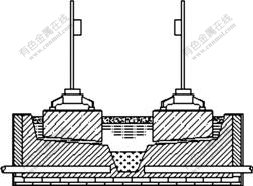
Fig.1 Schematic representation of drained cell

Fig.2 Meshed model of 75 kA drained cell
Element SOLID5 was used to model the electric parts of the cell. LINK68 was used to model the bus bars outside the cell. The influence of the temperature on the conductance of every electric part was considered during the model development. Structured mesh system was adopted in the model, as shown in Fig.2, with over 4��104 nodes and 3.3��104 elements.
Two types of boundary conditions, i.e., current and voltage potential were loaded. At the end of the anode risers (current entrance ends a and b in Fig.2), a current of 37.5 kA was applied respectively; and at the ends of cathode bus bars(current exit ends c and d in Fig.2), voltage potential of zero was applied. Default linear calculator was adopted in simulations.
3 Results and discussion
3.1 Distribution of electric fields
A cathode inclination angle of 4? was chosen to be the initial inclination angle (cathode inclination angle) of the 75 kA drained cell. Contours of voltage drop and vectors of current density of an anode are shown in Fig.3. The voltage drop of the anode is 0.334 V, which is close to that of the currently used H-H cells. According to the results, the voltage drop of the anode and cathode is 0.355 V. Due to the reduction of ACD, the voltage drop of the bath between the anode and the cathode decreases from 1.500 to 0.865 V. As the voltage drop of bath is lowered, the energy consumption of the electrolysis is reduced.

Fig.3 Contours of voltage (a) and vectors of current density (b)
It is found that the current in the anode stubs is close to each other, which ranges from 6.0 to 6.5 kA, as shown in Table 1, while large variety of current distribution appears among the cathode collector bars (see Table 2). From the entrance end to the exit end, the current in the anode stubs increases by about 170%. Comparing the current of the anode stubs with that of the cathode collector bars, it can be deduced that large horizontal current exists in the cell from the entrance end to the exit end. According to the previous experience, horizontal current possibly lies in aluminum pad because
Table 1 Current in anode stubs (Unit: kA)

Table 2 Current in cathode collector bars (unit: kA)
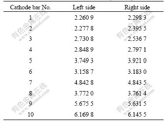
of its relatively low electric resistance. So the current distributions in the aluminum pad were analyzed below.
Vectors of the current density in the metal film are shown in Fig.4. Apparently, there exists great horizontal current. The y-direction horizontal current appears at the two ends of the cell. At the entrance end, the horizontal current directs to the central sump; while at the exit end, the current directs to two sides. In the middle part of the metal film, horizontal current is mainly in x-direction, from the entrance side to the exit side. The maximum current density of 600 kA/m2 exists at the entrance end near aluminum accumulation sump; the minimum current density of 2.719 kA/m2 exists at the exit end above the sump.

Fig.4 Vectors of current density (Unit: kA/m2)
According to the simulation results, horizontal currents in the anode, bath and carbon cathode are small. So it can be ascertained that the horizontal current in the aluminum film is the main cause of the non-uniform current distribution in the cathode collector bars. On the other hand, the large horizontal current may be caused by the original bus bars configuration design of 75 kA aluminum reduction cell.
Cathode inclination angle and ACD are two important parameters for the drained cell. Therefore, the influences of the two parameters on the current distribution were analyzed as follows.
3.2 Influences of cathode inclination angle
Fig.5 shows the variation of current density in the metal film with the increment of the cathode inclination angle. According to Fig.4, the horizontal current is mainly in y-direction at two ends of the cell and in x-direction at two sides. So only the current density in y-direction at two ends, and the current density in x-direction at two sides are presented.

Fig.5 Variation of current density with cathode inclination angle: (a), (b) In y-direction; (c), (d) In x-direction
From Fig.5, it can be seen that the distribution of the current density in the aluminum film is in symmetry to the central sump.
Fig.5(a) indicates that the current density (in y-direction) increases gradually from two sides to the central sump at the entrance end, and at the edge of the sump it reaches the maximum value. As the cathode inclination angle increases, the maximum value of the current density increases as well.
While at the exit end, the distribution of current density (in y-direction) is different from that of the entrance end (see Fig.5(b)). From two sides to the central sump, it increases at first, and reaches the maximum value in the middle of the cathode inclination angle, and then decreases. As the cathode inclination angle increases, the maximum value of the current density decreases, which is reverse to that of the entrance end.
According to the results shown in Figs.5(c) and (d), the distribution of the current density (in x-direction) is similar to each other at the two sides of the cell. From the entrance end to the exit end, the current density increases at first, and reaches the maximum value at the middle of the cell, and then decreases. The maximum value of the current density decreases with the increase of cathode inclination angle.
The variation of the maximum current density in the metal film and coating layer with the increment of the cathode inclination angle is shown in Fig.6. It can be seen that, as the inclination angle increases, the maximum current density in the aluminum increases almost linearly, while the maximum current density in the coating layer decreases remarkably. From 2? to 15?, the maximum value of the current density in aluminum pad increases by 15%, while it decreases by 27% in the aluminum wettable coating layer.
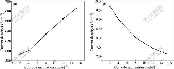
Fig.6 Maximum current density in metal pad (a) and in coating layer (b)
3.3 Influences of ACD
ACD control can be used to adjust the cell voltage and heat balance during the aluminum production electrolysis. Since the energy consumption is in direct proportion to the cell ACD, the increment of ACD should be prudential.
The ACD adjustment to the drained cell operation is of great importance. Firstly, the ACD of drained cells decreases a lot compared with that of the currently used H-H cells, so does the cell voltage drop. Hence, a workable heat balance of the electrolysis should be rebuilt; secondly, the flow fields of the melts in the ACD change as well; thirdly, if the current distribution in the metal film changes with ACD, the stability of the electrolysis should be guaranteed.
Fig.7 indicates the variation of the current density in the metal film with the increment of ACD. The distribution of the current density in the metal film change little as the ACD change from 1.5 to 4.0 cm. The current densities sampled at the entrance and exit end, and two sides of the cell are close to each other. Therefore, it can be concluded that the ACD adjustment from 1.5 to 4.0 cm has small impact on the current density distribution in the metal pad of a 75 kA drained cell. So the adjustment of ACD is determined by the heat balance and flow field designs of the drained cell, which will be studied in further work.

Fig.7 Variation of current density with ACD: (a), (b) In y-direction; (c), (d) In x-direction
4 Conclusions
(1) Great horizontal current exists in the aluminum film, which will cause a non-uniformity distribution of the current in the cathode collector bars.
(2) The current distribution in the aluminum and coating layer changes reversely with the variation of the cathode inclination angle. As the cathode inclination angle increases from 2? to 15?, the maximum current density in the aluminum increases by 15%, and the maximum current density in the coating layer decreases by 27%.
(3) ACD adjustment from 15 to 40 mm has small impact on current distribution in the metal pad.
(4) Further study will focus on the influences of ledge profile parameters on the current distribution in a 75 kA drained cell, and the influences of ACD variation on the heat balance and flow fields.
References
[1] LIU Ye-xiang. The study and development of the inert anode and wettable cathode in aluminum electrolysis [J]. Light Metals, 2001(5): 26-29. (in Chinese)
[2] YANG Bao-gang, YU Pei-zhi, YU Xian-jin, QIU Zhu-xian. Inert electrode materials for aluminum electrolysis [J]. Light Metals, 2000(5): 32-35. (in Chinese)
[3] BROWN G D, HARDIE G J, SHAW R W. TiB2 coated aluminium reduction cells: Status and future direction of coated cell in comalco [C]// Aluminium Smelting Conference. Queenstown, 1998: 529-538.
[4] FENG Nai-xiang. Drained-cathode aluminum cell with TiB2 composite cathode: CN, ZL01248353 [P]. 2002-05-08.
[5] FENG Nai-xiang, QI Xi-quan, PENG Jian-ping. Electrolysis test of 1.35 kA drained cathode reduction cell with TiB2-coated cathode [J]. The Chinese Journal of Nonferrous Metals, 2005, 15(12): 2047-2053. (in Chinese)
[6] LI Xiang-peng, LI Jie, LAI Yan-qing, LIU Ye-xing. Freeze profile and heat balance calculation of the 160 kA drained cell [J]. Acta Metallurgica Sinica: English Letters, 2004, 17(2): 215-220.
[7] LI Xiang-peng, LI Jie, LAI Yan-qing, LIU Ye-xiang. Physical modeling of the gas induced bath flow in a drained aluminum reduction cell [J]. Transaction of Nonferrous Metals Society of China, 2004, 14(5): 1017-1022.
[8] LI Xiang-peng, LI Jie, LAI Yan-qing, LIU Ye-xiang. Mathematical simulation of the gas induced bath flow in a drained aluminum reduction cell [J]. Transaction of Nonferrous Metals Society of China, 2004, 14(6): 1221-1226.
[9] MARC D, VALDIS B, DANIEL R. Impact of the vertical potshell deformation on the MHD cell stability behavior of a 500 kA aluminum electrolysis cell [C]// Light Metals 2008. New Orleans: TMS, 2008: 511-514.
[10] ROJAREVICS V, PERICLEOUS K. Comparison of MHD models for aluminium reduction cells [C]// Light Metals 2006. San Antonio, Texas: TMS, 2006: 347-352.
[11] JIANG Chang-wei, MEI Chi, ZHOU Nai-jun, LI Lu-ping, FU Jun-ping. Numerical simulation of current field in aluminum reduction cells using ERM and FEM [J]. Light Metals, 2006(12): 40-43. (in Chinese)
[12] LI Jie, LIU Wei, LAI Yan-qing, LI Qing-yu, LIU Ye-xiang. Coupled simulation of 3D electro-magneto-flow field in Hall-Heroult cells using finite element method [J]. Acta Metallurgica Sinica: English Letters, 2006, 19(2): 105-116.
[13] QI Xi-quan, FENG Nai-xiang. 3-D numerical calculation and analysis of electric field for the cathode of aluminum reduction cells [J]. Journal of Materials and Metallurgy, 2003, 2(2): 103-107.
[14] LIU Ye-xiang, LI Xiang-peng, LAI Yan-qing, LI Jie. Heat balance of a drained aluminum reduction cell [J]. Transaction of Nonferrous Metals Society of China, 2003, 13(5): 1199-1202.
[15] QI Xi-quan, FENG Nai-xiang, CUI Jian-zhong. Numerical simulation of current distribution in metal pad of aluminum reduction cells [J]. Transactions of Nonferrous Metals Society of China, 2005, 15(4): 931-937.
Foundation item: Project(2005CB623703) supported by the National Basic Research Program of China
Received date: 2009-03-01; Accepted date: 2009-05-24
Corresponding author: LI Jie, PhD, Professor; Tel: +86-731-88836268; E-mail: 13808488404@hnmcc.com
(Edited by CHEN Wei-ping)

