
Preparation of helicopter rotor counterbalance component by means of permanent-mold casting
LIU Zhao-jing(刘兆晶), ZUO Feng(左 锋), REN Shan-zhi(任善之), LI Feng-zhen(李凤珍)
Institute of Materials Science and Engineering, Harbin University of Science and Technology,
Harbin 150040, China
Received 6 May 2006; accepted 16 December 2006
Abstract: Copper alloy was adopted to prepare helicopter rotor counterbalance component by means of permanent-mold casting. Process parameters were determined on the basis of theory calculation and computer numerical simulation. Through controlling mould temperature, pouring temperature and speed, the defects, such as gas cavity, shrinkage porosity, cold shut, can be effectively avoided. The results show that the best process parameters for smelting are as follows: pouring temperature is 1 100 ℃, pouring time is 14 s and opened mould time is 6 min. Mixture of 90% charcoal powder and 10% fluorite were selected as covering agent and 0.01% phosphorus copper acts as oxidizer. The density of rotor counterbalance component after casting in permanent-mold is 99.91% of its theory density. Mechanical properties are as follows: σb=315 MPa, σ0.2=143 MPa, δ=25%, HB=950. The mass deviation is between -5 g and +5 g, the curved surface distortion is less than 0.20 mm, and the largest tolerance of sectional thickness can be controlled between -0.10 mm and +0.10 mm.
Key words: helicopter; rotor counterbalance component; permanent-mold casting; copper alloy; smelting and casting process; numerical simulation
1 Introduction
The manufacture of aircraft is a crucial sign of a national aviation level[1-3]. Rotor is one of the key components of the helicopter[4-6] and the counterbalance component is the important part of rotor. So the dimension of precision curved surface, surface quality, chemical composition and mechanical properties for counterbalance component require highly, and the mass deviation must be controlled in a very small range. So the fabrication process and quality guarantee system are particularly important. Casting process is a complicated physical and chemical process and the qualities of casting are affected by many factors. The final goal of casting is to prevent and eliminate casting defect[7-9]. In the present work, chemical compositions of helicopter rotor counterbalance component, mold design, smelting process, casting technology, numerical simulation of casting’s freezing course, prediction of casting defect were studied separately. Through strictly controlling each key link and important technical indexes, the integrated quality guarantee system was formed to insure the casting quality.
2 Preparation of copper alloy and establish- ment of casting model
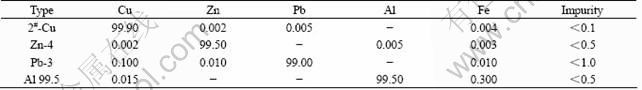
In order to meet mass requirement, dimension limitation and application performance of blade counterbalance, copper alloy was selected to prepare helicopter rotor counterbalance component. Electrolyzed copper, pure zinc ingot, pure lead ingot and pure aluminum were used to prepare copper alloy. Its chemical compositions are listed in Table 1.
Because the surface qualities of helicopter rotor counterbalance component are required strictly, it is difficult to satisfy the requests of the properties if using general cast method. Though accurate melt mould cast can meet the demands, the mass and properties are difficult to reach the technical indexes. It is comparatively suitable to adopt the permanent-mold casting after analysis and experiment.
The advantages of permanent-mold casting are that the surface quality is better and the shrinkage porosity can be reduced as well as the dimension precision is higher. Because cooling speed is very quick, the mechanical properties of casting can be improved and properties of helicopter rotor counterbalance casting can be met. Moreover, adopting permanent-mold casting can reduce the production cost, production cycle, pollution and energy consumption[10-12].
Raw materials were selected according to Table 1. The density at different parts of the copper alloy was determined after smelting and pouring in the permanent-mold. Test results show that the density of the edge part is 8.495 g/cm3, that of the heart part is 8.489 g/cm3 and that of the transmission district is 8.492 g/cm3. The theory density of the plumbous brass is 8.500 g/cm3 [13], so the density of copper alloy by permanent-mold casting can reach 99.91% of theory density. Air cavity, shrinkage porosity and so on, can be controlled in a smaller range, which can meet the technique requirement of rotor counterbalance component.
Table 1 Chemical compositions of copper alloy used in helicopter rotor counterbalance component (mass fraction, %)
3 Selection of casting schemes
There are two kinds of casting scheme to produce helicopter rotor counterbalance component. One is to pour horizontally, as shown in Fig.1(a), the second is to pour vertically, as shown in Fig.1(b).
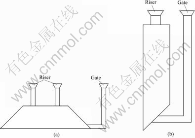
Fig.1 Schemes of horizontal pouring (a) and vertical pouring (b) for producing helicopter rotor counterbalance component
Although the first casting method requires lower shaping condition and is easy to pour shaping, it is available to exhaust, remove slag and mend shrinkage. Therefore, it is apt to produce casting defect. For the second casting method, it is not available to exhaust, remove slag and mend shrinkage though it is advantageous to pour shaping, so it is difficult to produce casting defect. Because the technique requirement for helicopter rotor counterbalance component is strict, the second method was adopted to guarantee its casting quality.
4 Shape and mould design of rotor counterbalance component
4.1 Shape design of rotor counterbalance component
The outline of the rotor counterbalance component is a complicated streamline shape with curved surface and its dimension precision requires extremely highly in which dimensional tolerance needs to reach CT7 grade. Shape assurance is the precondition of whole quality assurance.
First of all, theory outline of paddle was done by CATIA work station. And then the concrete dimensions of rotor counterbalance component outside the paddle were confirmed. Some problems are met during the course of design, so entity’s model was adopted finally and the formal rotor counterbalance component casting pattern was confirmed. The rotor counterbalance component plot is shown in Fig.2.
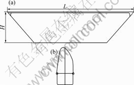
Fig.2 Diagrammatic view of rotor bob-weight part: (a) Eleva- tion; (b) Planform
4.2 Design of permanent-mold moulds
The material for fabricating permanent-mold should meet many requirements, such as good heat resistance, good heat conductivity and good mechanical processability, and a certain intensity, toughness and wearability[14]. The casting iron is one of the commonly used materials to produce permanent-mold. Gray casting iron HT200 was selected to make the permanent-mold mould when considering the requirement of rotor counterbalance component cast mould[15].
On the premise of guaranteeing rigidity, the thickness of mould was designed as 20 mm, with strengthening muscle structure in order to lighten the mass of the permanent-mold mould and to operate easily. The pedestal adopted the inclined plane in conformity with shape of helicopter rotor counterbalance component, and was fixed by locating pin and wedge iron. In order to prevent heat expansion and distortion of permanent-mold, the hook tightening and the bolt fastening were adopted synchronously. The grooving on surface of mould is to strengthen the heat dissipation ability of the mould, to obtain the fine crystalline grain, and to increase the compact degree and surface quality of the mould. On the basis of above analysis, a rational mould in structure was designed and its sectional plot is shown in Fig.3.
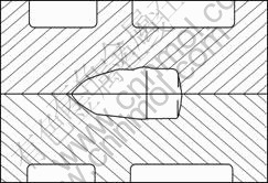
Fig.3 Sectional view of mould
One of the important parameters of permanent-mold design is the shrinking rate. According to the casting scheme above-mentioned, the practically measured shrinking rate of rotor counterbalance component was 1.71% after carrying out the pouring test.
5 Design of pouring system, computer numerical simulation and cast CAD
5.1 Pour temperature and time
According to phase diagram of Cu-Zn alloy[13], the liquid phase temperature of the alloy is above 903 ℃. By considering mobility of alloy, shrinkage, cast mould exhaust and so on, pouring temperature should be in the range of 1 050 to 1 150 ℃.
Pouring time is one of the important process parameters of permanent-mould cast, according to the following formula[16]:

where t is the pouring time, s; k is the pouring coefficient, k=2.5-4.0; d is the largest wall thickness of the cast, d=9.2 cm; m is the cast mass, m=9.0 kg. After calculation, tmin=10.90 s and tmax=17.43 s were obtained. So the pouring time can be controlled between 11 and 17 s.
5.2 Area of internal pouring road
The movement of particle in the ideal fluid has differential equation according to Bernolli equation[17]:
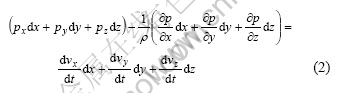
where p is the pressure of particle in the fluid; v is the velocity of fluid; ρ is the liquid density.
Suppose that only gravity acts on the particle in the fluid, namely, px=py=0; pz=-G; However, the copper alloy liquid has a certain viscidity, which will produce flow resistance[17], so the following equation can be obtained [18]:
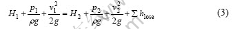
where H1 and H2 are the upper point and lower point position, respectively; p1 and p2 are the pressure of liquid metal at entrance and exit; ρ is the density of the liquid metal; g is the gravity acceleration; v1 and v2 are the velocity of liquid metal flow at the entrance and the exit, respectively; Σhlose is the total loss of the metal liquid overcoming different resistance in the pouring system, Σhlose=Σξpour(v2/2g); Σξpour is the sum of resistance coefficient in pouring system along the road and at local site.
The pouring system is an open system, so p1=p2=0. Suppose v1=0, v2=v, H1=H0, H2=0, put the conditions into Eqn.(3), the following equations can be obtained:
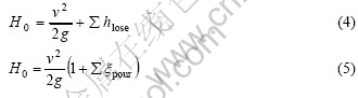
And then v can be worked out from Eqn.(5):
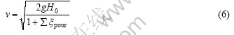
Metal liquid mass of internal pouring road: m2=ρAintv, where Ain is the section area of internal pouring road, then
Because
put
Put the time according to section 5.1 into Eqn.(8), and m2 =6 kg, H0=40 cm, μ is between 0.3 and 0.5, Amin=2.52 cm2, Amax=8.40 cm2 can be obtained and the diameter of internal pouring road is in the range of 8-27 mm.
5.3 Computer numerical simulation
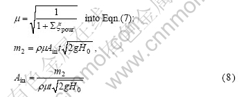
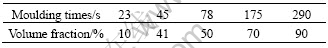
Put the parameters from test and calculation into the computer, the temperature fields at different times after filling are shown in Fig.4. Because the rotor counterbalance component mould is a metal material, the heat conduction ability is strong. However, gate, riser and pouring road part are sand mould, their cooling speeds are relatively slow. So the temperature of rotor counterbalance component drops fastest and solidifies firstly. It is good for riser to mend shrinkage and compact degree of casting. Meanwhile, the permanent-mould can guarantee that the casting has better surface roughness and dimension precision. The change of volume fraction along with filling mould time is listed in Table 2.
According to Fig.4 and Table 2, the open mould time was chosen as 5-8 min. The casting has been basically solidified over at this moment and casting temperature can be controlled below 500 ℃, which will not cause great internal stress and meet the design requirement.
Fig.4 Temperature fields of cast after different time: (a) 23 s; (b) 45 s; (c) 78 s; (d) 175 s; (e) 290 s
Table 2 Volume fraction of solid state at different time
The loose criterion of the cast during solidification is shown in Fig.5. From Fig.5, it can be seen that there is not shrinkage porosities and cavities after solidification. Meanwhile, the rising head is mended and contracted well and there is smaller shrinkage cavity at the riser and rising head, which does not influence the quality of cast.
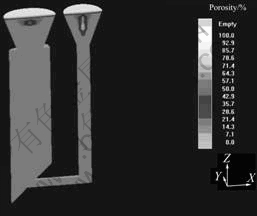
Fig.5 Loose criterion during solidification of cast
Computer simulation techniques were applied to predict the temperature field during cast solidification, which can guarantee that casts can be totally solidified and the greatest production efficiency can be obtained too. The quality of the cast can be also guaranteed through magma numerical simulation. Under the selected process conditions, the cast has not shrinkage porosities and cavities, which indicates that the scheduled mechanical properties and requirements can be achieved.
The best parameters calculated through computer simulation are as follows: Astraight?Aacross?Ainside=1.0?1.2?1.5; the diameter of inside pouring road is 25 mm; the height of rising head is two times of the cast average thickness, namely 110 mm; pouring temperature, pouring time and open mould time is 1 100 ℃, 14 s and 6 min, respectively.
6 Quality assurance of smelting and casting process of rotor counterbalance component
6.1 Smelting and casting process of rotor counter- balance component
Induction heating was selected to smelt the alloy and graphite crucible was chosen as the furnace wall. In the course of smelting, the key lies in controlling furnace temperature. The smelting temperature of copper alloy is generally controlled between 1 080 ℃ and 1 120 ℃. If the temperature is too high, burning loss of Zn will be accelerated. At the same time, a large amount of gas will be absorbed, which will result in the air hole during pouring, and shaping of casts will be influenced. Mixture of 90% charcoal powder and 10% fluorite were selected as covering agent[16] and 0.01% phosphorus copper was used as the deoxidizer at the same time. Under the smelting process here, the composition of counterbalance component and mass can meet requirement.
For casts through permanent-mold shaping, pouring process is an important step. Pouring temperature, pouring speed and mould temperature must be cooperated effectively, which can guarantee the shaping of casts and eliminate the surface defect. According to the computer simulation, pouring temperature, pouring time and mould temperature should be controlled in a range of 1 080-1 120 ℃, 13-16 s, and above 250 ℃.
Surface quality, dimensional tolerance and mechanical properties of rotor counterbalance component through permanent-mold shaping were sampled and tested. The test results are listed in Table 3.
Table 3 Tested results of rotor counterbalance component through permanent-mold shaping
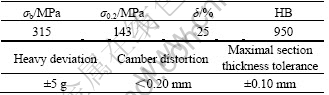
The above-mentioned results can satisfy the specification requirement and quality level of helicopter rotor counterbalance component.
6.2 Defect control of casts and quality guarantee
6.2.1 Control of composition and properties
Controlling the composition of copper alloy for rotor counterbalance component is to control the burning loss of Zn. The smelting temperature can not be too high and the staying time can not be too long. When the staying time is prolonged in the furnace after melting, Zn must be supplemented at any time in order to remedy quantity loss.
In mechanical properties, the main factor affecting the plasticity and hardness is content of Zn. Under balanced condition, the copper can dissolve 37%Zn. If the content of Zn exceeds 40%, a large number of β phases in matrix will be precipitated, which causes the plasticity to reduce and the hardness to increase. Considering every index of rotor counterbalance component, Zn content should be controlled in the range of 37%-38%. With the increase of pouring temperature, the plasticity will reduce and the hardness will increase. When the cooling speed increases, the plasticity reduces and the hardness does not change much[15].
6.2.2 Prevention of air hole and inclusions
The air hole, one of the defects, often appears in the copper alloy cast. The reason is as follows: It is not enough for deoxidation of melting liquid and removal of gas; unreasonable pouring system is designed; the volatile from gate and rising head are relatively great; pouring speed is too fast.
When content of Zn is higher in Cu-Zn alloy, Zn is extremely easy to be oxidized in the course of smelting and pouring. Especially in the copper liquid, when it flows in mould cavity, it is apt to present in the turbulent state, and Zn forms the oxidized zinc cotton fibre shape, which mixes on the copper liquid surface or adheres on the cavity surface of mould and forms inclusions. Only in the course of pouring, the copper liquid in the mould cavity keeps the laminar flow state throughout, which can well prevent the formation of oxidization inclusion.
7 Conclusions
1) Casting iron permanent-mold was selected to prepare helicopter rotor counterbalance component, whose density can reach 99.91% of theory density. According to theory calculation, computer numerical simulation, casting CAD and practical process experiment, the best smelting parameters were established as follows: pouring temperature, pouring time and opened mould time is 1 100 ℃, 14 s and 6 min, respectively.
2) In the course of casting, mixture of 90% charcoal powder and 10% fluorite was selected as covering agent and 0.01% of the phosphorus copper acts as oxidizer. After permanent-mold casting, mechanical properties of rotor counterbalance component can reach: σb=315 MPa, σ0.2=143 MPa, δ=25%, HB 950. The mass deviation is between -5 g and +5 g, curved surface distortion is less than 0.20 mm, and the largest sectional thickness tolerance can be controlled between -0.10 mm and +0.10 mm.
References
[1] CUI De-gang. Helicopter development and contemporary integrated manufacturing technology [J]. Aeronautical Manufacturing Technology, 2002, 27(4): 43-58. (in Chinese)
[2] CHEN Yi-shu. Development of chinese helicopter industry [J]. Aeronautical Manufacturing Technology, 2001, 25(6): 19-21. (in Chinese)
[3] ABOULAFIA R. Outlook and specifications of world helicopter industry [J]. International Aviation, 2002, 155(1): 31-34.
[4] LIN Yu-chen, JIN Meng-jiang. Improvement and development of foreign military helicopter [J]. Modern Defence Technology, 2000, 28(1): 1-8. (in Chinese)
[5] YANG Kai-tian. Speeding up rotor technology and bring an advance in Chinese helicopter industry [J]. Aeronautical Science and Technology, 2002, 12(2): 29-31. (in Chinese)
[6] XIANG Jin-wu, GUO Jun-xian, ZHANG Xiao-gu. An overview of rotor blades optimum design for helicopter vibration reduction [J]. Journal of Beijing University of Aeronautics and Astronautics, 2002, 27(1): 32-34. (in Chinese)
[7] PIAO Xue-dong, LI Xin-ya. Present situation and development tendency of permanent mould casting process of iron castings [J]. Modern Cast Iron, 2001, 21(1): 1-7. (in Chinese)
[8] QI Xiao-bing, LIU Zi-an, SHEN Ze-ji, PIAO Dong-xue, LI Yao-hui, YANG Li-jie. Study of copper alloy metal mold for castings [J]. Foundry Technology, 2001, 23(5): 49-53. (in Chinese)
[9] JOHN B. Selecting casting technology permanent mold’s perspective [J]. Modern Casting, 2003, 93(2): 43-45.
[10] TANG Ji. The situation and development of cast iron with permanent mold in China [J]. Foundry, 2000, 49(9): 516-518. (in Chinese)
[11] LERNER Y S. Status and developments in gravity die casting of iron [J]. Foundry Trade Journal, 1999, 32(5): 26-28.
[12] SHEPEL S V, PAOLUCCI S. Numerical simulation of filling and solidification of permanent mold castings [J]. Applied Thermal Engineering, 2002, 22(2): 229-248.
[13] Foundry Institution of Chinese Mechanical Engineering Society. Foundry Handbook(Nonferrous Alloy) [M]. Beijing: China Machine Press, 2003. (in Chinese)
[14] LIANG Jin-sheng, LIANG Guang-chuan, GAO Xing-hua. Study on the die material of copper-base alloy [J]. Heat Treatment of Metals, 1995, 38(9): 12-13. (in Chinese)
[15] Association for Compiling Handbook for Foundry Engineer. Handbook for Foundry Engineer [M]. Beijing: China Machine Press, 2003. (in Chinese)
[16] Foundry Academy of Japanese. Permanent-mold Casting of Iron [M]. Tokyo: Industry News Publishing House, 1976: 154-169. (in Japanese)
[17] SHEN Jing-chao. Engineering Hydrodynamics [M]. Beijing: China Machine Press, 1988. (in Chinese)
[18] CAO Wen-long. Casting Technology [M]. Beijing: China Machine Press, 1989. (in Chinese)
Corresponding author: LIU Zhao-jing; Tel: +86-451-86392562; E-mail: lzj956@21cn.com
(Edited by YANG Hua)

